background image


  Python II™ 


     Multichannel SDI/HD-SDI 
     Video Transport System


          Instruction Manual 


Telecast Fiber Systems, Inc. 

102 Grove Street 

Worcester, MA 01605 

Tel: 508-754-4858 

Fax: 508-752-1520 

6/07 

   www.telecast-fiber.com

Summary of Contents for Python II

Page 1: ...Python II Multichannel SDI HD SDI Video Transport System Instruction Manual Telecast Fiber Systems Inc 102 Grove Street Worcester MA 01605 Tel 508 754 4858 Fax 508 752 1520 6 07 www telecast fiber com ...

Page 2: ...2 Python II Transceiver front and rear views Software version Number ...

Page 3: ...ooting 14 Specifications 15 Warranty 16 List of Figures Figure 1 Rear Panel Connections 7 Figure 2 Front panel 8 channel TX CWDM 7 Figure 3 Front panel 8 channel RX CWDM 7 Figure 4 Toggling through the channels 8 Figure 5 n a no link indication 9 Figure 6 Good link but no SDI Data 9 Figure 7 Good link AND good SDI Data 9 Figure 8 Python II with Band Splitter Option 12 Figure 9 Example of Python II...

Page 4: ...o fiber is attached to the fiber port There are no user adjustments inside the Python II Do not attempt any type of service to this instrument other than any as instructed this manual Refer all servicing to Telecast Fiber Systems Inc FCC Part A Manual Notice This equipment has been tested and found to comply with the limits for a Class A digital device pursuant to part 15 of the FCC rules These li...

Page 5: ...d HDTV all with no pathological data errors In addition the Python II supports the 75 Mb sec and 125 Mb sec digital outputs of our Adder II line of audio multiplexers Coax is equalized on both the inputs and outputs at 1 5 Gbps and the outputted data stream is not re clocked Python II s are housed in a standard 19 inch electronics rack and are 1 RU high This manual covers the following part number...

Page 6: ... Mounting Units feature integrated rack ears that are a part of the frame Place each unit in its intended location before attaching any cables or fibers to prevent accidental damage to the cables or their connectors Line Power Any power supply used with the Python II must provide a minimum of 1 5 amps continuous at 12 to 24 VDC Two 4 pin DC power inputs are provided for redundancy There is no inte...

Page 7: ...ical for the TX TR and RX units see Figure 2 The rear panel has 1 2 8 or 16 ST type connectors dependent upon version Front Panel Connections Indicators The front panels of the RX and TX are shown on the next page in Figure 3 The front panel will have 8 or 16 BNC connectors Figure 2 Front Panel 8 Channel CWDM TX Figure 3 Front Panel 8 Channel CWDM RX ...

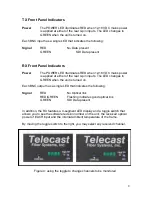
Page 8: ...ither of the rear 4 pin inputs The LED changes to GREEN when the unit is turned on Each BNC output has a single LED that indicates the following Signal RED No Optical link RED GREEN Flashing indicates good optical link GREEN SDI Data present In addition the RX features a 4 segment LED display and a toggle switch that allows you to see the software revision number on the unit the received optical p...

Page 9: ...7 and 30 This is because when there is no data present at the TX the laser turns on and off until SDI is present This is also why the individual RX channel LED blinks RED GREEN Figure 6 Variable optical power levels NO SDI present 3 When the optical link is good AND a valid SDI data stream is present an optical power level will be indicated Depending on the loss in the fiber run this number could ...

Page 10: ...Inspect the fiber ends and clean them with with Kim Wipes that have been wet with pure isopropyl alcohol Fingerprints or other dirt on the optical connector end surfaces will reduce the received optical signal level Connect the fibers to their matching ports on both the TX and RX units Optical Transmitter Losses The maximum fiber distance is defined by the optical loss margin The RX signal must be...

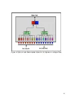
Page 11: ...nternal course wavelength division multiplexer combines multiple SDI channels optically onto a single fiber For example in a P2 8TX 13CW ST 8 channels are optically muxed to a single ST connector All 8 signals are then sent to the receiver over one fiber where they are de muxed and presented on the front panel BNCs On a 16 channel unit two ST connectors would be present on the rear panel There are...

Page 12: ...12 Figure 8 Python II with Band Splitter Option for 16 Signals on a Single Fiber ...

Page 13: ...oint distribution With Optical splitting optional a single TX unit can send to multiple RX units When combined with other Telecast modules like the Rattler Viper II 5292 5259 and 5270 and Viper I 292 and 259 many different signal topologies are possible Figure 9 Example of Python II flexibility ...

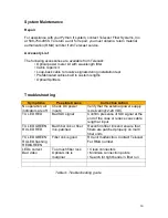
Page 14: ...ptoms Possible Cause Corrective Action No operation all indicators are off Check DC power inputs Verify that the external power supply is delivering12 24 VDC TX LED RED Bad SDI signal Confirm presence of SDI signal at the end of the coax or reduce coax cable length at input TX LED GREEN RX LED RED Bad fiber link or fiber mis patched Reconfirm fiber link and ensure that fibers are patched properly ...

Page 15: ...ignal channels Transmission Method Digital Input Level 800 mV peak to peak Interface Up to SMPTE 292M Input Output Impedance 75 Ohm Return Loss 15 db Coaxial Input Equalization Max Rate 1 5 Gbps EQ 1 5 Gpbs 300 meters of Belden 8281 HD Bit Error Rate 22dBm RX optical power 10 12 Jitter on path error test 0 2 UI Power Requirements Voltage 12 to 24 VDC Current 1 5 Amp Power 15 watts Mechanical Envir...

Page 16: ...te maintenance and care Nor shall this warranty apply to any damage caused in whole or in part by attempts by personnel other than Telecast s personnel as approved in advance in accordance with the foregoing provisions to open install repair or service the Product nor to damage resulting from improper connection with incompatible equipment nor to damage to a unit which has been modified by personn...

Reviews: