
Quick Start Guide
M-Series Sonars (incl. Mk2)
Doc. No. QG21283 / Part No. 1015281
July 2020
Install ProViewer Software
Insert the USB key.
Run Setup.
If prompted, click “Do not block”.
Configure your PC network interface card
Set your PC Network IP address to 192.168.1.3
Set the Net Mask to 255.255.255.0
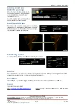
Bench Test the Sonar
Connect the sonar as shown here.
(The various components may differ in appearance.)
Connect the sonar cable to the SONAR J1 port
on the POE box.
Connect the Ethernet cable to the PC J2 port
on the POE box and to the computer.
Apply AC power to the POE box. Wait approx.
45 seconds for the connection.
Start the ProViewer Software, and click the
Connect button
to connect to the sonar.
User
computer
Ethernet cable
Benchtop Test Setup
110-240VAC
POE box
Sonar to
surface cable
Sonar
head
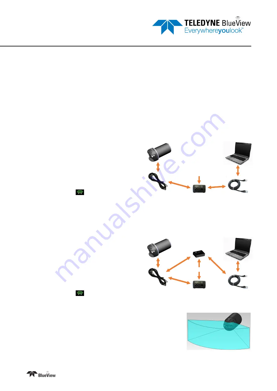
Bench Test the Sonar with VDSL
Connect the sonar as shown here.
(The various components may differ in appearance.)
Connect the RJ45 on the sonar cable to the
SONAR J1 port on the POE box.
Connect the RJ11 on the sonar cable to the
SONAR port on the VDSL box.
Connect the Ethernet cable to the PC port on
the VDSL box and to the computer.
Apply AC power to the POE and the VDSL
boxes. Wait approx. 60 seconds for the
connection.
Start the ProViewer Software, and click the
Connect button
to connect to the sonar.
User
computer
Ethernet cable
Benchtop Test Setup
with VDSL
110-240VAC
POE box
25 ft sonar to
surface cable
VDSL topside box
RJ11
RJ45
Sonar
head
Mount the Sonar
The sonar head should be mounted looking forward, preferably on the
same pan-and-tilt as the ROV’s main camera.
Note:
Your sonar might look different than the picture shown, but the same
concept applies.


