background image

GX Series


HD Digital Video Recorder

GX684 / GX689 / GX6816

User Guide

Summary of Contents for GX Series

Page 1: ...GX Series HD Digital Video Recorder GX684 GX689 GX6816 User Guide ...

Page 2: ...ction 12 3 3 Setup for Broadband Internet Connection 16 4 Local Operation 20 4 1 Icons Description 20 4 2 OSD Menu 21 4 2 1 OSD Menu Operation 21 4 2 2 OSD Menu Structure 23 4 3 Basic Operation 65 4 3 1 View Live Video 65 4 3 2 Recording 66 4 3 3 Playback 69 4 3 4 PTZ 70 4 4 Advanced Operation 73 4 4 1 Install Alarm Sensors and Relay Control Port 73 4 4 2 Install Tamper Circuit and External Resist...

Page 3: ...tion 101 4 4 9 Import and Export 103 4 4 10 User Account 104 4 4 11 SMS 107 5 Remote Operation 108 5 1 Remote Operation 108 5 1 1 Port Mapping Setup 108 5 1 2 sureLINK Setup 108 5 2 Icons Description 109 5 3 Basic Operation 111 5 3 1 View Live Video 111 5 3 2 Recording 113 5 3 3 Playback 115 5 4 Advanced Operation 116 5 4 1 Hard Disk Formatting 116 5 4 2 Hard Disk Scanning 116 5 4 3 Hard Disk Turn...

Page 4: ... 5 4 6 Pan Tilt Zoom 129 5 4 7 Footage Extraction 132 5 4 8 Throughput Control 132 5 4 9 Switch Control 133 5 4 10 Time Synchronization 134 5 4 11 Import and Export 135 5 4 12 User Account 136 5 4 13 Maintenance Log Backup 137 Appendix A Safety Instruction 138 Appendix B Limited Warranty 139 Appendix C sureLINK Technology 140 Appendix D Firmware Upgrade 145 Appendix E Security Mode 146 Appendix F ...

Page 5: ...nd other countries All other trademarks are the property of their respective owners Copyright c 2015 Signal Communications Limited A member of TeleEye Group All rights reserved Version 1 00 Limits of Liability and Disclaimer of Warranty Signal Communications Limited has taken care in preparation of this manual but makes no expressed or implied warranty of any kind and assume no responsibility for ...

Page 6: ...nt data streams to assure optimized video recording and transmission performance across different environments TeleEye GX680 has developed special video streaming protocols that provide extra security during Internet transmission The 5 protection layers incorporated in the TeleEye video surveillance solutions are able to shield off hacker s attacks via the Internet TeleEye GX680 Series HD digital ...

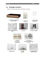
Page 7: ...ithin the package 5 Mouse 6 Power Adaptor 3 Registration code sheet 10 HDD screws 11 Straight through Ethernet cable 2 Warranty card 9 Software CD 7 Resistors for tamper detection 1 TeleEye GX HD digital video recorder 8 Alarm port connector alarm port cover 4 HDD recommendation sheet ...

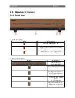
Page 8: ...bile network Support both static dynamic IP Independent video network require only one IP for up to 16 MX HD Video Cameras IP filtering Single point video throughput control Mobile video monitoring Triplex operation simultaneous video monitoring recording playback HD video output Multiple login accounts Compliance with BS 8418 Sophisticated event management Multi language OSD Mouse control 1 3 Con...

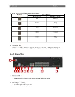
Page 9: ...hen power on Light up when performing recording Blink when an event is triggered 2 Main control buttons Button Description Select camera Enter password Quick button for recording Display next cameras Start sequential mode Change to next screen mode e g Full Quad Open main OSD menu Back to previous menu ...

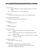
Page 10: ... Up Pause Down Stop Left Rewind Right Forward Enter Play 4 Front USB port For mouse control firmware upgrade footage extraction setting import export 1 4 2 Back View 1 Power switch Switch on or off the TeleEye GX HD Digital Video Recorder 2 Power input 16V DC Power supply to TeleEye GX 1 2 3 4 5 6 7 8 9 10 ...

Page 11: ... TV output HDTV output connector 8 Audio in out port PA Audio In Connect to audio input device e g amplified microphone for recording Audio Out Connect to audio output device e g amplified speaker to generate output audio signal Audio PA Connect to audio output device e g amplified speaker to facilitate remote public addressing 9 Digital video input ports RJ 45 connectors for video source input 10...

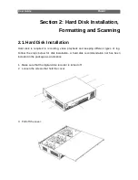
Page 12: ... required in recording video playback and keeping different types of log Follow the steps below for disk installation A hard disk recommendation list has been included in the package as a reference 1 Make sure that the digital video recorder is turned off 2 Loosen the screws that hold the cover 3 Pull off the cover ...

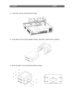
Page 13: ...User Guide PAGE 8 4 Loosen the screws of the hard disk holder 5 Insert HDD into one of the available holders Maximum 4 HDD can be installed 6 Mount the HDD to the holder with attached screws ...

Page 14: ...User Guide PAGE 9 7 Remount the hard disk holder to TeleEye GX 8 Connect the SATA cable to the HDD ...

Page 15: ...ce it is reconstructed it would be readable and writable by the digital video recorder User can also perform disk formatting manually The function can be found in the OSD menu Main Menu HDD Recording Disk Management Format Format the selected hard disk Format All Format all installed hard disks 2 3 Hard Disk Scanning Hard disk scanning is a maintenance function similar to the Scan Disk function pr...

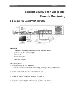
Page 16: ...eras and their power adaptors CAT 5 cable VGA TV monitor VGA HDTV cable Setup Procedures 1 Install a hard disk to the TeleEye GX If there is no hard disk installed Recording and Playback are not functional 2 Connect cameras to the video ports of TeleEye GX 3 Connect a monitor to the VGA output of TeleEye GX 4 Plug in the power adaptors to TeleEye GX cameras and monitors ...

Page 17: ... format they would be formatted automatically when startup completes 7 TeleEye GX is ready for operation Live video should appear on the monitor By default manual recording will be started automatically 3 2 Setup for LAN Connection Equipment TeleEye GX HD Digital Video Recorder and its power adaptor Cameras and their power adaptors CAT 5 cable Network switch or router PC ...

Page 18: ...sk to the TeleEye GX If there is no hard disk installed Recording and Playback are not functional 2 Connect cameras to the video ports of TeleEye GX 3 Plug in the power adaptors to TeleEye GX and cameras 4 Connect TeleEye GX to the network switch 5 Switch on the power switch of TeleEye GX 6 If all installed hard disks are not in TeleEye GX recognized format they would be formatted automatically wh...

Page 19: ... the IP address of the router The DNS setting is used for sureLINK time synchronization and e mail notification 5 To access the TeleEye GX double click the row representing the digital video recorder A web browser should be opened automatically The first 3 fields of IP address of the PC should be the same as that of TeleEye GX 6 Besides accessing through IP Setup Utility user can also open a web b...

Page 20: ... and press Connect The default administrator password is 0 digits of serial number There is an example Serial Number GXS11529 User Name admin Default Password 011529 Details can be found in the registration code sheet 8 Live video is shown after successful connection ...

Page 21: ...l Core i3 Processor RAM 2 GB HDD 10 GB free space Display Direct 3D Nvidia GeForce GT 220 ATI Radeon HD 5450 or above OS Windows XP Windows Vista or Windows 7 Other Requirements Java Sun Microsystems Java 2 runtime Version 1 5 0 or above IE Windows Internet Explorer Version 6 or above Setup Procedures on GX Side 1 Install a hard disk to the TeleEye GX If there is no hard disk installed Recording a...

Page 22: ...leEye GX 6 If all installed hard disks are not in TeleEye GX recognized format they would be formatted automatically when startup completes Setup Procedures on PC Side 1 Configure the network settings of TeleEye GX through PC with LAN connection 2 Install TeleEye IP Setup Utility NET framework is also needed for the operations Both can be found in the included software CD 3 Run IP Setup Utility ...

Page 23: ...ateway should be the IP address of the router The DNS setting is used for sureLINK time synchronization and e mail notification 6 Reconnect the digital video recorder to the Internet network 7 Configure other network settings for TeleEye GX and the PC if necessary such as router port mapping firewall etc Please refer to the manual of the router 8 Open a web browser and type the IP address plus por...

Page 24: ...and press Connect The default administrator password is 0 digits of serial number There is an example Serial Number GXS11529 User Name admin Default Password 011529 Details can be found in the registration code sheet 10 Live video is shown after successful connection ...

Page 25: ...Motion event Recording Video loss event Playback Power failure event Pause in playback Disk usage alert event Fast Forward in playback HDD fault event Backward in playback Audio enabled Digital Analog PTZ control PTZ tite up PTZ tite down PTZ pan left PTZ pan right PTZ function only for analog PTZ PTZ command subtract only for analog PTZ PTZ command add only for analog PTZ PTZ command up only for ...

Page 26: ...Panel Buttons Press button 1 to 9 to select Camera 1 to 9 Press button 0 first then press button 0 to 6 to select Camera 10 to 16 Quick button to change recording to on off or schedule Display next page of cameras e g Cam 2 Cam 3 Hold down the button for a few seconds to start sequential mode Switch to next screen mode e g Full 2x2 Menu button used to open and close main OSD menu or navigate backw...

Page 27: ...ing through the OSD user will see different types of item Their properties are listed below Item Name Description Yes No box 2 options only Click on it to toggle the option Spin box 3 or more options available Click on the arrows to choose another option Drop down box Multiple options available Click on it to show all available options Click on an option to select it Edit box Require user to enter...

Page 28: ... only be opened by right clicking the mouse Camera Selection Panel Show currently displaying cameras Click to display selected camera in full screen All Display all cameras Mode Select the display mode Next Display next camera Sequential Start sequential mode Switch 1 Switch 4 Toggle the status of the switch Playback Display recording log Recording Change recording to on off or schedule OSD Menu O...

Page 29: ...tings System Log Display event connection operation and setting log System View server information Change system settings e g IP date time language Event Status Display event status Clear event status Playback Display recording log Start video playback Switch Control the switches Change switch settings Event Handler Change event settings Footage Extraction Extract recorded video to USB flash devic...

Page 30: ...video quality Frame Rate Set recording frame rate applied to all cameras Auto Record at highest achievable frame rate 1 fps Record at 1 frames per second Custom Enable custom frame rate for individual camera Custom Frame Rate Set recording frame rate of individual cameras Disk Mode Set disk mode Cyclic Remove oldest data when hard disk full Fixed Stop recording when hard disk full Schedule Recordi...

Page 31: ...l Scan all installed hard disks Format All Format all installed hard disks For execution a local password of current user is required in advanced mode Main Menu HDD Recording Schedule Recording Add Add a new recording schedule Edit Edit the selected schedule Delete Delete selected schedule Delete Day Delete all schedules of a day as the selected schedule ...

Page 32: ...Set recording frame rate of the schedule not applicable for Custom frame rate Recording Type Type of recording schedule Normal Record when within schedule Motion Record when motion detected and within schedule Custom Record based on individual camera setting ADD Confirm add the schedule setting Motion Setting Set motion detection settings Main Menu HDD Recording Schedule Recording EDIT Most settin...

Page 33: ...ed video at selected time Main Menu HDD Recording Recording Recording Press MENU button can hide or display progress bar during recovering OK Start recover local password of current user is required in advanced mode CANCEL Back to previous page Main Menu System Log Event Log Display event log Connection Log Display remote connection log Setting Log Display setting log Operation Log Display operati...

Page 34: ...t triggered Reset Event reset Tamper Event tampered Arm System armed Disarm System disarmed Secu Switch On Security switch turned on Secu Switch Off Security switch turned off Entry Event trigger within entry delay Exit Event trigger within exit delay Action Show event associated actions Show previous next page of log Show different types of event log ...

Page 35: ...tion date and time Access Show IP of the remote host Status Show connection status Remark Show type of connection Dial in Triggered by user Dial back Triggered by dialback action User Show the user connected to video server through remote software Show previous next page of log ...

Page 36: ...lue of the setting Access Show IP of the remote host or Local for local host User Show the user performed the change Show previous next page of log Main Menu System Log Operation Log Date Time Show date and time of the operation Operation Show operation that is done Access Show IP of the remote host or Local for local host User Show the user performed the operation Show previous next page of log ...

Page 37: ...h date Time Set the search time OK Search for log closest to the date and time Main Menu System Log Event Log Log Option If an event log entry is associated with the recording action pressing enter or double clicking will enter Log Option menu Search Log Enter Search Log menu Video Playback Enter Recording Log menu with date and time of event log ...

Page 38: ...hange dedicated network settings Camera Setting Change camera settings Date Time Change date and time settings Network Change connection throughput and 3G modem settings External Keyboard Set external keyboard settings Privacy Mask Set PTZ privacy mask PTZ Set PTZ arguments Display Change local monitoring and audio settings Audio Setting Set audio input and output System Upgrade Upgrade system fro...

Page 39: ...sion Display firmware version of the digital video recorder CPLD Version Display CPLD version IP Display IP address of the digital video recorder Port Display port number of the digital video recorder Subnet Mask Display subnet mask of the digital video recorder Gateway Display gateway of the digital video recorder Primary DNS Display primary DNS of the digital video recorder Secondary DNS Display...

Page 40: ...ontrast Saturation Set video saturation Sharpness Set the sharpness to make video more sharp Exposure Set the exposure when video is too dark Mirror Set video mirroring to display image in different way Normal Normal display H Flip Left right flip V Flip Top down flip HV Flip Left right flip top down flip White Balance Set the white balance when video color displayed is not correct Flickerless Set...

Page 41: ...he focus HD Resolution Adjust the resolution 702p 1080p Restore Default Restore camera factory settings Undo Undo current change Main Menu System Date Time Time Synchronization Enable Enable disable time synchronization Time Zone Set the time zone Country Select a country Date Set system date Time sync disabled only Time Set system time Time sync disabled only CHANGE TIME Save the time settings Ti...

Page 42: ... recorder Auto DNS Enable disable auto DNS Primary DNS Set primary DNS of the digital video recorder Secondary DNS Set secondary DNS of the digital video recorder Broadband Stream Throughput Set the data rate of broadband connection Narrowband Stream Throughput Set the data rate of narrowband connection Mobile Stream Throughput Set the data rate of mobile connection sureLINK Setting Change sureLIN...

Page 43: ...eLINK address of the digital video recorder Refresh Period Set the sureLINK refresh rate Main Menu System Network Setting IP Filtering Mode Set the IP filtering mode Disable Disable IP filtering Allow Only allow selected IP address to connect Deny Disallow selected IP address to connect Filtered IP Address Set the IP range to be filtered ...

Page 44: ...ss Show ending IP of the filtered IP range Add Add an IP filtering entry Delete Delete the selected IP filtering entry Delete All Delete all IP filtering entries Show previous next page of filtered IP address Main Menu System Network Setting IP Filtering Filtered IP Address Add Start IP Address Set starting IP to be filtered End IP Address Set ending IP to be filtered Add Add the filter entry ...

Page 45: ...dress Change starting IP of the filtering range End IP Address Change ending IP of the filtered range Edit Edit the filter entry Main Menu System Network Setting 3G USB Modem Manufacturer Manufacturer name Model Model Revision Firmware version Operator 3G network operator Signal Strength 3G network signal strength from 0 to 100 IP Address 3G network IP Driver Version Modem driver version ...

Page 46: ...t UPGRADE DRIVER Upgrade 3G modem driver from USB device Main Menu System Network Setting 3G USB Modem Profile Setting Access Point Name Dialup Access Point Name Dial Number Dialup Number User Name 3G network login user name Password 3G network login password Main Menu System Network Setting Video Network Setting Auto Server IP Enable Disable the video network setting IP Address Set the IP address...

Page 47: ... PTZ control RS 485 Baud Rate Set RS 485 input baud rate Main Menu System Privacy Mask User can draw privacy mask by mouse or buttons Camera Selected video channel Mask ID Selected privacy mask id Mask Status Enable disable current privacy mask change current camera center Edit size of selected privacy mask DELETE Delete current privacy mask ...

Page 48: ... position for displaying system time Camera Name Enable Display hide camera name Sequential Time Set the switch time between cameras in sequential mode Sequential Camera Choose cameras displayed in full screen sequential mode Default Display Mode Set the default display mode OSD Font Color Set the font color of OSD items Video Out Resolution Set the output display resolution Change Resolution Conf...

Page 49: ...e of audio BUILT IN use video server on board audio input CAMERA use external camera audio input PA Channel Set PA channel PA Installed Enable disable PA channel PA Channel Source Select PA channel source BUILT IN use video server on board audio output CAMERA use external camera audio output Live Output Select audio live output channel Main Menu System Lock Keys Lock Keys Manually enable lock key ...

Page 50: ...ystem System Upgrade Progress Bar Display the upgrade progress Upgrade Upgrade the firmware from USB flash device Main Menu System Import Export Import Import settings from USB flash device Export Export settings to USB flash device ...

Page 51: ...cted Date Time Export date time settings if selected Connection Export network settings if selected Event Handler Export event settings if selected E mail Dialback Export e mail and dialback settings if selected Server Export server settings if selected OSD Export OSD settings if selected Select All Select deselect all settings Export Export the selected settings to USB flash device ...

Page 52: ...oss status Arm Disarm Tamper Show arm disarm tamper status Security Switch Tamper Show security switch tamper status System Tamper Show system tamper status Power Failure Show power failure input status Disk Full Show hard disk usage status HDD Fault Show hard disk available status System Restart Show system restart status Clear Event Clear event that has already reset ...

Page 53: ...ras that performed recording in yellow bars Event Select Display detail of the selected event Show previous next page of recording log Display recording log in smaller time scale Display recording log in bigger time scale Search recording log by date and time Extract video from selected time slot Search a camera record ...

Page 54: ...ange switch settings Main Menu Switch Switch Setting ID Select the switch Switch X Name Change the name of switch X Switch X Type Change the type of switch X Latching Turn on for a period of time Push button Turn off 1 second after it is turned on Switch X Normal State Change the normal state of switch X N O Normal open N C Normal close Action Delay Action setting set the time between turning off ...

Page 55: ...only Alarm Change individual alarm settings Motion Change motion detection settings Video Loss Change video loss event settings System Tamper Change system tamper event settings Power Failure Change power failure event settings Disk Usage Change disk usage warning event settings HDD Fault Change HDD fault event settings System Restart Change system restart event settings ...

Page 56: ...arm disarm control status Schedule Arm Disarm Enable disable schedule arm disarm Schedule Arm only Normal Arm Schedule Set weekly arm disarm schedule Schedule Arm only Holiday Arm Schedule Set holiday arm disarm schedule Schedule Arm only Main Menu Event Handler Arm Disarm Normal Arm Schedule No Show the schedule number Start Time Show the start time of system armed End Time Show the end time of s...

Page 57: ...hedule Add Add the new normal arm schedule Main Menu Event Handler Arm Disarm Holiday Arm Schedule No Show the schedule number Start Date Show the start date of schedule End Date Show the end date of schedule Start Time Show the start time of system armed End Time Show the end time of system armed Add Add a holiday arm schedule Delete Delete the selected holiday arm schedule Show previous next pag...

Page 58: ... new schedule End Time Set the end time of new schedule Add Add the new holiday arm schedule Main Menu Event Handler Security Switch Enable Enable disable the security switch On State Select circuit open close as security switch on Tamper Type Set the tamper detection type Associate Switch Associate switch 2 to security switch status Tamper Action Set actions taken when security switch is tampered...

Page 59: ...r on board alarm CAMERA use external camera alarm Sensor Type Select circuit open close as normal alarm state Tamper Type Set the tamper detection type Zone Type Set the zone type Entry Delay Set the entry delay time Entry Exit Zone only Exit Delay Set the exit delay time Entry Exit Zone only Action Set actions taken when alarm is triggered or tampered ENABLE DISABLE ALL Enable disable all alarm ...

Page 60: ...Exit Zone only Action Set actions taken when motion is detected ENABLE DISABLE ALL Enable disable all motion Main Menu Event Handler Motion Motion Detection Setting Select Select motion blocks Deselect Deselect motion blocks Select All Select all motion blocks Deselect All Deselect all motion blocks Sensitivity Set the sensitivity level Area Set the area sensitivity Custom sensitivity only Level S...

Page 61: ... Select circuit open close as normal state Action Set actions taken when system tamper is triggered Main Menu Event Handler Power Failure Enable Enable disable power failure event Sensor Type Select circuit open close as normal state Action Set actions taken when power failure is detected Main Menu Event Handler Disk Usage Enable Enable disable disk full event Warning Level Set the warning level A...

Page 62: ...vent Action Set actions taken when system restart abnormally Main Menu Event Handler Any Event Action Recording Change event recording settings Switch Change event switch settings Dial Back Change dialback settings E mail Change e mail settings SMS Change SMS settings Buzzer Change buzzer settings Event LED Change event LED settings Live Camera Change event associated live camera settings PTZ Chan...

Page 63: ...ing Camera Select cameras performing event recording Main Menu Event Handler Any Event Action Switch Enable Enable disable switch action of that event Switch Select switches turning on when event triggers General Switch Setting Set the latch duration and action delay Main Menu Event Handler Any Event Action Dial Back Enable Enable disable dialback action of that event Retry Duration Sec Set the ti...

Page 64: ... Event Action E mail Enable Enable disable e mail action of that event Image Attachment Associate Camera Change event associated camera for image attachment SMTP Server Change SMTP settings E mail X Set the e mail address of recipient X Sender E mail Set the e mail address of sender Action Delay Set the minimum time between 2 e mails of the same event Max Number of E mail Set the maximum e mails o...

Page 65: ... used in authentication Network Setting Change the network settings Time Out Set the allowed time of sending an e mail in each trial in minute Retry Set the number of retrial if fails to send the mail Main Menu Event Handler Any Event Action SMS Enable Enable disable SMS action of that event Phone Number Set recipient phone number Action Delay Set the minimum time between 2 SMS of the same event M...

Page 66: ...vent LED Enable Enable disable LED action of that event Main Menu Event Handler Any Event Action Live Camera Enable Enable disable live camera action of that event Associate Camera Select cameras to be displayed when event triggers Main Menu Event Handler Any Event Action PTZ Enable Enable disable live camera action of that event Associate Camera Select PTZ cameras to be displayed when event trigg...

Page 67: ...gth of the footage Protection Enable disable password protection Password Set extraction password Password protection enabled only EXTRACT Start backup using above settings Main Menu User Security Mode Select security mode Advanced Log in and access right required Current User Display current log in user Add Account Add new account Advanced mode only Edit Delete Account Edit or remove an account A...

Page 68: ...ocal operation Account Setting Enable Access right setting System Setting Enable Access right setting Recording Setting Enable Access right setting Video Backup Enable Access right setting Event Control Enable Access right setting Camera Control Enable Access right setting Playback Enable Access right setting Audio Enable Access right setting Video Monitoring Enable Access right setting Switch Ena...

Page 69: ...Enable Enable disable local log in with remote log in right only SAVE Save the account settings DELETE Delete the account Show settings of previous next account Main Menu User Power On Default Right Most settings are the same as Add Account menu SAVE Save the access rights when server startup or local user log out ...

Page 70: ...a 10 to 16 Hold down button 0 for a few seconds to change the display resolution Display next page of cameras e g Cam 2 Cam 3 Hold down the button for a few seconds to start sequential mode Switch to next screen mode e g Full 2x2 Hold down both buttons for a few seconds to refresh the local display When OSD menu is opened the control buttons won t take effect B By Mouse Right click Open the Screen...

Page 71: ... and stopped according to user defined schedules Schedules are set on a weekly basis When schedule recording is enabled manual recording will be disabled Event Recording Event recording will be activated if an event is triggered with its recording action enabled It can be performed with manual recording or schedule recording simultaneously Detail description and setup procedure will be given later...

Page 72: ...ity Frame Rate Set recording frame rate applied to all cameras Auto Record at highest achievable frame rate 1 fps Record at 1 frames per second Custom Enable custom frame rate for individual camera Custom Frame Rate Set recording frame rate of individual cameras Disk Mode Set disk mode Cyclic Remove oldest data when hard disk full Fixed Stop recording when hard disk full Schedule Recording View or...

Page 73: ...ing schedule Normal Record when within schedule Motion Record when motion detected and within schedule Custom Record based on individual camera setting Weekdays Select the weekdays to apply the schedule Start Time Set the start time of the schedule End Time Set the end time of the schedule Camera Select the cameras to apply the schedule Frame Rate Set recording frame rate of the schedule not appli...

Page 74: ... video channels can be played at the same time Main Menu Playback Date Show date of recording log Time Show time of recording log 1 2 16 Show cameras that performed recording in yellow bars Event Select Display detail of the selected event Show previous next page of recording log Display recording log in smaller time scale Display recording log in bigger time scale Search recording log by date and...

Page 75: ...ghlighted by icon Only digital PTZ control can be taken or If the video channel not support analog PTZ control For analog PTZ supported channel User can click or for taking PTZ command after the command box pop up on video monitoring screen User can deselect the PTZ control channel by using or then the video channel will be pointed by icon OSD object selection Digital Analog PTZ control PTZ tite u...

Page 76: ...l saved patrol STOP PATROL Stop patrol CLEAR PATROL Clear patrol 1 START TOUR REC Start tour recording STOP TORU REC Stop tour recording SET LIFT LIMIT Set life limit position for auto pan SET RIGHT LIMIT Set right limit position for auto pan Main Menu System Privacy Mask Setting User can draw privacy mask by mouse or buttons Camera Selected video channel Mask ID Selected privacy mask id Mask Stat...

Page 77: ... Speed Set pan speed Tit Speed Set tilt speed Patrol Speed Set patrol speed Dwell Time Set dwell time for patrol Main Menu System External Keyboard Support External Keyboard Display support of external keyboard Server ID Set DVR id for PTZ control RS 485 Baud Rate Set RS 485 input baud rate ...

Page 78: ... 35 Relay 1b Pin 17 Relay 2a Pin 36 Relay 2b Pin 18 Relay 3a Pin 37 Relay 3b Pin 19 N A 4 4 2 Install Tamper Circuit and External Resistors TeleEye GX supports tamper detection on all alarm inputs including arm disarm input security switch input system tamper and power failure input DEOL Dual End of Line termination with NC and NO connection SEOL Single End of Line termination with NC and NO conne...

Page 79: ...on S C Alarm Sensor drive output close point A and B LoZ Normal Sensor drive output open point A and B O C Tamper Wire open point A and B Term Status Description S C Tamper Wire short point A and B LoZ Normal Sensor drive output close point B and C HiZ Alarm Sensor drive output open point B and C O C Tamper Wire open point A and B Term Status Description S C Tamper Wire short point A and B LoZ Nor...

Page 80: ...y DEOL Normal Close Tamper Short Normal Close Alarm Open Tamper Open DEOL Normal Open Tamper Short Alarm Close Normal Open Tamper Open SEOL Normal Close Tamper Short Normal Close Alarm N A Alarm Open SEOL Normal Open Alarm Close Normal Open Alarm N A Tamper Open NC without tamper Normal Close Alarm N A Alarm N A Alarm Open NO without tamper Alarm Close Alarm N A Alarm N A Normal Open Alarm N A Ala...

Page 81: ...red the icon will remain static on its original position 4 4 3 1 Arm Disarm Arm Disarm input is used for enhancing security level of the surveillance area This input introduces the concept of 3 zone types of alarm and motion fire zone normal and entry exit zone Armed If the system is armed alarm sensor and motion that is set as normal zone can be triggered immediately if someone triggers the senso...

Page 82: ...holiday schedule it will follow holiday schedule instead of normal schedule Arm Disarm Tamper Type Arm Disarm tamper event triggers if someone cuts the wire between the arm disarm input and the digital video recorder This event can be triggered once the wire is being cut Arm Disarm tamper type has choice of none SEOL and DEOL Arm State If arm state is set to close it indicates arm of TeleEye GX wh...

Page 83: ...arm disarm control status Schedule Arm Disarm Enable disable schedule arm disarm Schedule Arm only Normal Arm Schedule Set weekly arm disarm schedule Schedule Arm only Holiday Arm Schedule Set holiday arm disarm schedule Schedule Arm only Main Menu Event Handler Arm Disarm Normal Arm Schedule No Show the schedule number Start Time Show the start time of system armed End Time Show the end time of s...

Page 84: ...hedule Add Add the new normal arm schedule Main Menu Event Handler Arm Disarm Holiday Arm Schedule No Show the schedule number Start Date Show the start date of schedule End Date Show the end date of schedule Start Time Show the start time of system armed End Time Show the end time of system armed Add Add a holiday arm schedule Delete Delete the selected holiday arm schedule Show previous next pag...

Page 85: ...rt Security Switch Tamper Type Security switch tamper event triggers if someone cuts the wire between the security switch input and the digital video recorder This event can be triggered once the wire is being cut Security switch tamper type has choice of none SEOL and DEOL On State If security switch on state is set to close it indicates security switch on and off of TeleEye GX when the state of ...

Page 86: ...e state of the circuit is opened it indicates alarm trigger of TeleEye GX while nothing happens when the state of the circuit is closed If the alarm sensor input circuit type is normal open NO when the state of the circuit is closed it indicates alarm trigger of TeleEye GX while nothing happens when the state of the circuit is open Zone Type All alarm sensors can be associated with zone types if A...

Page 87: ...les recording action recording action is automatically activated during entry delay The detail description is shown as follows 1 User turns off security switch 2 The alarm is set at entry delay 3 The 1st trigger is made by Alarm 4 i e user enters the surveillance zone and the entry delay time begins 4 2nd 3rd and 4th trigger are made and each entry delay starts respectively 5 User disarms the syst...

Page 88: ...User arms the system 2 The alarm is set at exit delay and timer of all alarms begin 3 The 1st trigger is made by Alarm 1 i e user leaves the surveillance zone 4 2nd 3rd and 4th triggers are made respectively 5 User turns on the security switch or waits for all alarm exit delays to expire For example if the time for leaving the surveillance zone is about 8 minutes user should adjust the delay time ...

Page 89: ... recording action recording action is automatically activated during entry delay The detail description is shown as follows 1 The alarm is set at entry delay 2 The 1st trigger is made by Alarm 4 i e user enters the surveillance zone and the entry delay time begins 3 2nd 3rd and 4th trigger are made and each entry delay starts respectively 4 User disarms the system for maintenance For example If th...

Page 90: ...s shown as follows 1 User arms the system 2 The alarm is set at exit delay and timer of all alarms begin 3 The 1st trigger is made by Alarm 1 i e user leaves the surveillance zone 4 2nd 3rd and 4th triggers are made respectively 5 User waits for all alarm exit delays to expire For example if the time for leaving the surveillance zone is about 8 minutes user should adjust the delay time so that Del...

Page 91: ...larm Recording starts if action enabled Security switch on Exit delay ends Recording stops Alarm can be triggered any time after that Exit delay ends after preset exit time Recording stops Alarm can be triggered any time after that Arm On Security switch off Trigger alarm Entry delay starts Recording starts if action enabled Disarm No alarm trigger Recording stops Entry delay ends after preset ent...

Page 92: ...nable disable the alarm Name Change the name of alarm Source Type Select source of alarm BUILT IN use video server on board alarm CAMERA use external camera alarm Sensor Type Select circuit open close as normal alarm state Tamper Type Set the tamper detection type Zone Set the zone type Entry Delay Set the entry delay time Entry Exit Zone only Exit Delay Set the exit delay time Entry Exit Zone onl...

Page 93: ... is internally divided into four sub blocks The definition of area is how many sub blocks have detected motion in order to trigger a motion event Any value between 1 and 4 can be set The more sub blocks are selected the lower the motion sensitivity is Main Menu Event Handler Motion Camera Select a camera Enable Enable disable motion event Motion Detection Setting Set motion detection settings Zone...

Page 94: ...nsitivity only Level Set the light sensitivity Custom sensitivity only OK Save the motion detection settings 4 4 3 5 Video Loss Video loss event will be triggered when the video channel input disappears or the digital video recorder receives no signal from the camera When this happens a blue screen would be displayed on the local monitor Main Menu Event Handler Video Loss Camera Select a camera En...

Page 95: ...le nothing happens when the state of the circuit is closed If the alarm sensor input circuit type is normal open NO when the state of the circuit is closed it indicates system tamper of TeleEye GX while nothing happens when the state of the circuit is open Physical Configuration for System Tamper The system tamper input and ground of TeleEye GX HD digital video recorder need to connect to an exter...

Page 96: ... it indicates power failure of TeleEye GX while nothing happens when the state of the circuit is open Physical Configuration for Power Failure Input The power failure input and ground of TeleEye GX digital video recorder need to connect to an universal power supply circuit UPS in order to detect any power failure condition The UPS circuit setup above is used as an example Not all UPS have signal o...

Page 97: ...ceeds warning level 4 4 3 9 HDD Fault HDD fault event will be triggered when hard disk failure bad health or hard disk change with respect to checklist is detected Main Menu Event Handler HDD Fault Enable Enable disable the HDD fault event Action Set actions taken when disk failure or lost 4 4 3 10 System Restart System restart event will be triggered when abnormal restart of video recorder is det...

Page 98: ...event recording is between 1 and 2 minutes before the event is detected User can find that there is at least 1 more minute of video in the recording log before event triggering Post Event Recording After the event is reset recording will continue until user defined duration time is reached Main Menu Event Handler Any Event Action Recording Enable Enable disable event recording of that event Record...

Page 99: ...hing type switch Action Delay Action delay is the period of time after the switch is turned off and before turning on again Example of Latch Duration and Action Delay Assuming that the latch duration is 10sec and action delay is 10sec If an event is triggered the on off status of the switch versus time is shown below Main Menu Event Handler Any Event Action Switch Enable Enable disable switch acti...

Page 100: ...be installed to the PC to perform dialback Main Menu Event Handler Any Event Action Dial Back Enable Enable disable dialback action of that event Retry Duration Sec Set the time between each dialback retrial Retry Count Set the number of retrial if dialback fails Entry X Change the settings of dialback entry X Dial Back Test Start the dial back test Main Menu Event Handler Any Event Action Dial Ba...

Page 101: ... of sender Action Delay Set the minimum time between 2 e mails of the same event Max Number of E mail Set the maximum e mails of an event until event clear E mail Test Start the e mail test Main Menu Event Handler Any Event Action E mail SMTP Server Server Address Set the SMTP server address Port Set the SMTP server port Authentication Is authentication required for the SMTP server User Name Set u...

Page 102: ... test 4 4 4 6 Buzzer The built in buzzer of the digital video recorder can give Beep sound that draws nearby operator s attention when an event is triggered Main Menu Event Handler Any Event Action Buzzer Enable Enable disable buzzer action of that event Action Delay Set the time between turning off and next turning on Duration Set the time for turning on the buzzer 4 4 4 7 Event LED The event LED...

Page 103: ...camera action of that event Associate Camera Select cameras to be displayed when event triggers 4 4 4 9 PTZ Event associated PTZ camera will move to set preset position when an event is triggered Operator can immediately know what is happening at the site The PTZ action would only be performed once until user clears the event Main Menu Event Handler Any Event Action PTZ Enable Enable disable live ...

Page 104: ... Menu Footage Extraction USB Storage Device Select device for saving the footage FORMAT Format the selected USB device Mode Set extraction mode Normal Extract at the same recording frame rate with audio Quick Extract selected cameras at low frame rate no audio Channel Choose video channels to extract Select or Quick mode only Start Date Set start date of the footage Start Time Set start time of th...

Page 105: ... the digital video recorder Subnet Set subnet mask of the digital video recorder Gateway Enable Enable disable the gateway Gateway Set gateway of the digital video recorder Auto DNS Enable disable auto DNS Primary DNS Set primary DNS of the digital video recorder Secondary DNS Set secondary DNS of the digital video recorder Broadband Stream Throughput Set the data rate of broadband connection Narr...

Page 106: ...TeleEye GX can be synchronized with timeserver in the network using the time synchronization function The GX can work as a timeserver if internal time server is enabled Main Menu System Date Time Time Synchronization Enable Enable disable time synchronization Time Zone Set the time zone Country Select a country Date Set system date Time sync disabled only Time Set system time Time sync disabled on...

Page 107: ...hange connection throughput and 3G modem settings External Keyboard Set external keyboard settings Camera Setting Change camera settings Privacy Mask Setting Set PTZ privacy mask General PTZ Setting Set PTZ arguments Display Setting Change local monitoring and audio settings Audio Setting Set audio input and output Lock Keys Change key lock settings Firmware Upgrade Upgrade firmware from USB devic...

Page 108: ...evice Cancel Cancel the operation Main Menu System Setting Import Export Export Video Export camera settings if selected Recording Export recording settings if selected Switch Export switch settings if selected Date Time Export date time settings if selected Connection Export network settings if selected Event Handler Export event settings if selected E mail Dialback Export e mail and dialback set...

Page 109: ... startup or local user logout access right of local menu will follow the setting of Power On Default Right Please refer to the appendix for detail Main Menu User Security Mode Advanced security mode Log in and access right required Current User Display current log in user Add Account Add new account Edit Delete Account Edit or remove an account Power On Default Right Access right when not logged i...

Page 110: ...ocal operation Account Setting Enable Access right setting System Setting Enable Access right setting Recording Setting Enable Access right setting Video Backup Enable Access right setting Event Control Enable Access right setting Camera Control Enable Access right setting Playback Enable Access right setting Audio Enable Access right setting Video Monitoring Enable Access right setting Switch Ena...

Page 111: ...Enable Enable disable local log in with remote log in right only Save Save the account settings Delete Delete the account Show settings of previous next account Main Menu User Power On Default Right Most settings are the same as Add Account menu Save Save the access rights when server startup or local user log out ...

Page 112: ... ip and port try dialback only 3G connection established successfully hang Disconnect 3G network immediately only take effect in SMS EVENT mode profile X Set 3G dialup profile to X 1 or 2 Main Menu System Network Setting 3G USB Modem Manufacturer Manufacturer name Model Model Revision Firmware version Operator 3G network operator Signal Strength 3G network signal strength from 0 to 100 IP Address ...

Page 113: ... you can access your TeleEye GX anytime and anywhere by the IP address and port number through web browser The address should be in this format http IPAddress Port The default port number is 1024 which can be used for port mapping 5 1 2 sureLINK Setup sureLINK technology is a group of additional functions and services available in TeleEye GX so as to make it connect to the Internet in any connecti...

Page 114: ...n the following table Icon Description Recording Playback 1 3 2 4 Screen mode selection panel 1 Change page 2 Change mode 3 Max screen 4 Full screen Camera selection panel 1 6 2 7 3 8 4 9 5 10 Event status panel 1 Video loss event 2 Motion event 3 HDD event 4 Power failure event 5 Alarm tamper event 6 System tamper event 7 Alarm event 8 Siren on off 9 Armed Disarmed 10 Clear event ...

Page 115: ...6 3 7 4 Menu panel 1 Server Setting 2 Audio 3 PTZ 4 View log 5 Advanced 6 Footage extraction 7 Switch 1 2 On screen event status 1 Motion 2 Video loss 1 4 2 5 3 Playback panel 1 Rewind 2 Play 3 Pause 4 Stop 5 Fast forward Digital PTZ Analog PTZ ...

Page 116: ...Number e g http 192 168 0 12 1024 or sureLINK address in web browser address bar Procedures for getting a sureLINK address can be found in the appendix 2 By default advance security mode is applied and user name is not required Enter password and press Connect The default administrator password is 0 digits of serial number There is an example Serial Number GXS11529 User Name admin Default Password...

Page 117: ...f the web page it implies that Java JVM is not installed in the computer It can be obtained through the following methods Install through the software CD in the package Download from http www java com and install it If the camera setting does not fit the environment select Server Video Audio Setting Video Properties to change the configuration ...

Page 118: ...ecording mode A Manual Recording The start stop operation is controlled manually by operator Recording will be performed on all cameras once started 1 To start or stop manual recording click on Recording button on the main panel 2 To change recording settings go to Server Recording in setting page ...

Page 119: ...on the main panel 2 To view or edit the schedules go to Server Recording Scheduled Recording 3 To select a schedule simply click on the graphical representation of the schedule A list of that day s schedules will show on the right hand side C Recording Rebuild Recording log can be recovered by using recording rebuild function when user can not play back the recording User can go to Server Recordin...

Page 120: ... 5 3 3 Playback Recorded video can be played back through web browser without affecting the recording process 1 Click on Playback button to show the recording log 2 Choose a log entry and select a camera to start playback ...

Page 121: ...anning Disk scanning is performed in an attempt to fix noticeable hard disk error and to enhance its performance and reliability Remote login password is required for this operation Go to Server Disk Management click Scan all disk in remote setting page Do not close the browser or alter the hard disk until the process is complete 5 4 3 Hard Disk Turn On OFF Problematic disk can be drawn from recor...

Page 122: ...ase refer to 4 4 1 Install Alarm Sensors and Relay Control Port for setup detail and 4 4 3 Event Handling for descriptions of different events and their corresponding settings 5 4 4 1 Arm Disarm Arm Disarm input is used for enhancing security level of the surveillance area 1 Go to Server select Event Matrix Event Arm Disarm 2 To change arm disarm settings click on Arm Setting ...

Page 123: ...User Guide PAGE 118 3 To add or remove arm schedules click on Schedule Setting Use the tap Normal and Holiday on the top left corner to select normal schedule or holiday schedule ...

Page 124: ...5 4 4 2 Alarm Alarm can be used to detect many events such as fire and illegal entering by someone 1 Go to Server select Event Matrix Event Alarm 2 Click on Alarm Setting and select appropriate settings in the pop up menu ...

Page 125: ... camera 1 Go to Server select Event Matrix Event Motion 2 Click on Setting to pop up Motion Setting menu Left click mouse and drag to select the surveillance area or right click mouse and drag to deselect the area Outlines of selected blocks will display in red color Blocks filled with red color means motion is detected ...

Page 126: ...perational zone 5 4 4 4 Video Loss Video loss event is triggered when the digital video recorder receives no signal from the camera A blue screen would be displayed when this happens 1 To enable video loss detection go to Server Event Matrix Event Video loss ...

Page 127: ...abinet and destroying the digital video recorder 1 To change the event settings go to Server Event Matrix Event System Tamper 5 4 4 6 Power Failure This event is triggered when any power failure condition is detected 1 To change the event settings go to Server Event Matrix Event Power Failure Input ...

Page 128: ... specified warning level 1 To change the event settings go to Server Event Matrix Event Disk Usage Level 5 4 4 8 Disk Fault Disk available event is triggered when hard disk change or failure is detected This event is enabled by default 1 To disable the event go to Server Event Matrix Event Disk Fault ...

Page 129: ... will be taken immediately after the system is started up again 1 To enable the event go to Server Event Matrix Event System Restart 5 4 5 Event Action User can define the set of actions to be taken by TeleEye GX when an event is triggered This section shows the configuration of action settings Please refer to 4 4 4 Event Action for descriptions of different actions and their settings ...

Page 130: ...tings go to Server Event Matrix Event Choose an event and click on Recording column 5 4 5 2 Switch If an event is associated with switch action user selected switches will turn on when this event is triggered 1 To change the switch properties go to Server Event Matrix Action Switch 2 To enable the switch action go to Server Event Matrix Event Choose an event and click on Switch column ...

Page 131: ...lly when this event is triggered 1 To change the settings go to Server Event Matrix Action Dial Back 2 To enable the action go to Server Event Matrix Event Choose an event and click on Dial Back column The Java web page can t respond to dialback request software like TeleEye sureSIGHT or sureGUARD needs to be installed to the PC to perform dialback ...

Page 132: ... Matrix Action E mail 2 To enable the action go to Server Event Matrix Event Choose an event and click on E mail column 5 4 5 5 SMS If an event is associated with SMS action a notification SMS will be sent when this event is triggered 1 To change SMS settings go to Server Event Matrix Action SMS 2 To enable the action go to Server Event Matrix Event Choose an event and click on SMS column ...

Page 133: ... 4 5 7 Event LED If an event is associated with LED action the LED built on the front panel of TeleEye GX will blink when this event is triggered This action is enabled by default To disable the action go to Server Event Matrix Event Choose an event and click on LED column 5 4 5 8 Live Camera If an event is associated with live camera action real time live video of pre selected cameras will be dis...

Page 134: ...t position when this event is triggered To change the settings go to Server Event Matrix Event Choose an event and click on PTZ column 5 4 6 Pan Tilt Zoom PTZ PTZ operations can be performed easily when a PTZ supported camera is connected to TeleEye GX digital video recorder 1 Go to Menu PTZ to open the PTZ control panel ...

Page 135: ... camera up Tile the camera down Pan the camera left Pan the camera right Zoom in Zoom out Pan automatically until Auto Off is clicked Stop the auto pan operation Set the pan speed Set the tilt speed Configure the desired direction and lens settings as the preset positions for recall preset and patrol operation ...

Page 136: ...g the 16 numeric buttons Start the patrol operation when Patrol1 is clicked Stop the patrol operation when Stop Patrol is clicked Restore default setting by clicking Set Default Delete the patrol 1 by clicking Clr Patrol 1 Move to preset 1 automatically when left idle for a certain time with Home On activated Cancel the Home On operation by clicking Home Off ...

Page 137: ...es open the selected folder and double click TPPlayer exe to view the extracted video 5 4 8 Throughput Control Throughput control can limit the output data rate of the digital video recorder To avoid possible downgrade in video monitoring performance this setting should be configured to fit the network bandwidth Go to Menu Server Setting Connection ...

Page 138: ...esides controlling through event action user can also control the external switches directly 1 Go to Menu Switch and click on a button to toggle the switch status 2 If user wants to change the switch settings go to Menu Server Setting Switches ...

Page 139: ... The time in the digital video recorder can be synchronized with timeserver using the time synchronization function 1 Go to Menu Server Setting Date Time 2 After changing the time settings user can click Time Synchronization Test to perform testing ...

Page 140: ...ideo recorder will be restarted automatically after import process is completed 1 Go to Setting page select Import at the lower left corner of the page 2 In the pop up menu select the setting file to be imported B Export 1 Go to Setting page select Export at the lower left corner of the page Select the configurations to be exported 2 Upon completion a message box will pop up and show the path of t...

Page 141: ...ly accounts with the User Account access right have the privilege to modify the account settings Please refer to the appendix for details 1 Go to Menu Server User Setting 2 To add new account click Add To modify or remove an account select an existing account and click Edit or Delete respectively User name of an account cannot be changed after creation ...

Page 142: ...User Guide PAGE 137 5 4 13 Maintenance Log Backup Maintenance log of the digital video recorder can be extracted Go to Menu Server Setting Maintenance Log Backup click start to start backup process ...

Page 143: ... prevent it from overheating these openings must not be blocked or covered The openings should never be placed near a radiator or heat source or in a built in installation unless proper ventilation is provided 4 This product should be operated from the type of power indicated on the marking label If you are not sure of the type of power available consult your dealer or local power company 5 The ha...

Page 144: ...ht to charge Customer an inspection fee on site service fee or cost of parts if i no fault in the equipment can be found during inspection or ii the defect is caused at conditions those mentioned in point 5 above or iii Customer fail in providing access methods to the site or the equipment e g specified access permit or key Such determination is up to the sole discretion of TeleEye 7 The warranty ...

Page 145: ... work on broadband Internet economically and cost effectively and perform remote live video monitoring anytime and anywhere conveniently sureLINK Address You can apply for a sureLINK address domain name such as www hkpublic TeleEye TeleEye net for your digital video recorder You can use this name to login or browse the built in web server One of the advantages is that you are not required to memor...

Page 146: ... web site at http www TeleEye com Follow the steps below 1 Enter http www TeleEye com in your web browser address bar to access our web site Click on Customer Login button 2 Login using your registered name and password New customers need to sign up first 3 Select sureLINK Registration ...

Page 147: ...de in the fields provided Then click on Next button The process is then completed Reference Registration Code is printed on the registration Code Sheet The application will be processed once we received your domain name registration Normally it requires about 1 working day to activate sureLINK for your TeleEye GX You will receive a notification mail when your sureLINK service is ready ...

Page 148: ...eleEye Product Support again and follow the steps below 1 Login in at http www TeleEye com 2 Go to sureLINK Registration Associate Device Modification 3 Select a sureLINK address Domain Name you want to modify 4 Enter the old registration code new digital video recorder serial number and new registration code in the fields provided 5 Click Modify button to submit the form If the above procedure is...

Page 149: ...lity to access GX web page by double clicking the row represent your GX digital video recorder 2 Click on Menu Server Setting select Connection Network 3 Scroll down to sureLINK section 4 Select Using sureLINK address to enable sureLINK function 5 Type in the registered address 6 Select a time period for GX to update its IP address to sureLINK server ...

Page 150: ...video recorder Step 4 Enter the menu Main Menu System Firmware Upgrade Click Upgrade to start the upgrade Step 5 After upgrade the digital video recorder will be restarted Enter the menu Main Menu System Server Information to check the firmware version Network Upgrade Step 1 Get ready the TeleEye GX firmware upgrade file rxp Step 2 Turn on the GX digital video recorder Step 3 Connect to the digita...

Page 151: ...eo backup Recording System setting User account Advanced security mode supports 6 concurrent users Advanced security mode User account Account structure Type Description Remark General setting User name Login user name from remote software 4 16 characters Case insensitive Unique between each account Account type Local Network Both Allow user to login from local OSD remote software both Access righ...

Page 152: ...follow the setting of Power On Default Right Administrator account ADMINISTRATOR Type Default Remark User name ADMINISTRATOR Fixed Account type both Fixed Access right All Fixed Network password 0 digits of serial number Available to change Local password 0 digits of serial number Available to change Local time out 15 mins Available to change Power on default right Type Default Remark Access right...

Page 153: ... setting 1 Video format camera installation Change live video quality brightness contrast Network setting throughput control setting Date Time setting Hard disk formatting scanning Recording setting Switch setting Event setting Firmware upgrade Shutdown restart User account 2 User account setting Changing of security mode Setting import export Restore factory setting At least one camera should be ...

Page 154: ...video remotely through network Site Monitoring Method There are two methods to link up with the digital video recorder to view video TCP IP in LAN TCP IP on the Internet using Broadband and Internet Router Depending on the connection method chosen follow Section 3 to configure the digital video recorder before use so as to make it function properly The built in web server or TeleEye surveillance a...

Page 155: ...ra tilt duration PTZ Zoom Duration Change PTZ camera zoom duration PTZ Focus Duration Change PTZ camera focus duration PTZ Iris Duration Change PTZ camera iris duration PTZ Additional Duration Change PTZ camera additional duration PTZ Washer Duration Change PTZ camera washer duration PTZ Wiper Duration Change PTZ camera wiper duration PTZ Patrol Speed Change PTZ camera patrol speed PTZ Dwell Time ...

Page 156: ...m disarm associate switch 1 Secu Switch On State Change security switch on state Associate Switch 2 Enable disable security switch associate switch 2 Alarm Name Change alarm sensor name Alarm Sensor Type Change alarm sensor type Motion Block Change motion detection block Motion Sensitivity Change motion detection sensitivity Motion Level Change motion detection level Motion Area Change motion dete...

Page 157: ...mera action Event PTZ Enable disable PTZ action of the event Event PTZ Cam Change camera associated to PTZ action Event PTZ Preset Change PTZ camera recall preset position Server Name Change digital video recorder name Registration Check Enable disable registration checking Web Server Enabled Enable disable built in web server Security Mode Change security mode Add Account Add a new account Delete...

Page 158: ...emote interface Import Setting Import settings Export Setting Export settings Local Login Local user login Local Logout Local user logout Remote Login Remote user login Remote Logout Remote user logout Software Arm Armed from remote interface Software Disarm Disarmed from remote interface Enable Schedule Arm Start schedule arm mode Disable Schedule Arm Stop schedule arm mode System Startup Start t...

Page 159: ...channels 4 RCA Line level Output impedance 30KOhm Frequency 200 3500Hz AUDIO OUTPUT No of channels 1 for Playback 1 for PA RCA Line level Output imedance 600Ohm Frequency 200 3500Hz RECORDING Mode Manual schedule motion event driven HDD SATA internal x4 Max recording rate at 1080p 100fps 225fps 400fps Playback Forward backward pause step forward step backward fast forward COMMUNICATION Network RJ ...

Page 160: ...ailure Disk Failure Action Buzzer dial back local recording relay control e mail notificationBuzzer Dial back Local recording Relay control Email notification SMS PTZ External alarm inputs 16x NC NO with tamper detection RELAY SWITCH No of channels 4 Max rating 24V AC 1000mA POWER Voltage 16V DC Max rating 80W OPERATING ENVIRONMENT Ambient temperature 5 C 50 C Relative humidity 85 no condensation ...

Reviews: