background image


TinyOne Plus 868MHz Terminal User 
Guide


1vv0300826

 Rev.3 – 14/01/2011  


Summary of Contents for M868-TinyPlus

Page 1: ...TinyOne Plus 868MHz Terminal User Guide 1vv0300826 Rev 3 14 01 2011...

Page 2: ...8MHz Terminal User Guide Reproduction forbidden without Telit Communications S p A written authorization All Rights Reserved page 2 of 47 1vv0300826 Rev 3 14 01 2011 This document is related to the fo...

Page 3: ...any injury loss or damage of any kind incurred by use of or reliance upon the information Telit disclaims any and all responsibility for the application of the devices characterized in this document...

Page 4: ...12 II 7 DIGITAL CHARACTERISTICS 14 II 8 ORDERING INFORMATION 15 CHAPTER III MECHANICS AND CONNECTION 16 III 1 MECHANICAL CHARACTERISTICS 16 III 2 CONNECTIONS 17 III 3 CABLES DESCRIPTION FOR IP67 CASIN...

Page 5: ...istinct chapters General characteristics describes the electrical and mechanical characteristics Mechanics and connections details the casing connector cabling and power supply Functionalities lists t...

Page 6: ...1 2011 I 3 Document change log R Re ev vi is si io on n D Da at te e C Ch ha an ng ge es s ISSUE 0 29 04 09 First Release ISSUE 1 21 06 10 Updated reference documents table ERC 70 30 recommendation ta...

Page 7: ...communication Standard Institute FM Frequency Modulation FSK Audio Frequency Shift Keying GFSK Gaussian Frequency Shift Keying GMSK Gaussian Minimum Shift Keying IF Intermediary Frequency ISM Industri...

Page 8: ...channel spacing specified 0 1 Annex7 d 869 2 869 25 10 25 0 1 Annex7 b 869 25 869 3 10 25 0 1 Annex7 e 869 3 869 4 10 25 1 Annex1 g3 869 4 869 65 500 25 for 1 or more channels 10 Annex7 c 869 65 869 7...

Page 9: ...tions are excluded Russian Federation No info National Restrictions for non specific SR devices Annex 7 band a e Country Restriction Reason Remark Band A France Duty cycle limited to 0 1 Russian Feder...

Page 10: ...Maximum Unit Operating Temperature 40 25 85 C Relative humidity 20 75 Storage Temperature 40 25 85 C Relative humidity 0 95 II 3 Mechanical Characteristics Mechanical characteristics Characteristics...

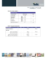
Page 11: ...s Characteristics IP67 casing Unit Power Supply 6 to 40 V Transmission consumption 25mW 6V 60 12V 35 40V 15 mA Reception consumption 6V 30 12V 25 40V 10 mA Stand by consumption 70 A II 5 Timing Charac...

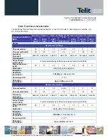
Page 12: ...el 0 868 025 868 6125 868 725 869 2125 869 4125 869 6625 869 725 Transmission Output Power under 50 4 levels selectable by software see Hayes command ATS202 Max output power mW 25 10 25 10 25 25 5 Mod...

Page 13: ...ission Output Power under 50 4 levels selectable by software see Hayes command ATS202 Max output power mW 25 25 25 5 Modulation GFSK with 20 kHz deviation Reception Sensitivity for CER 10 3 102 dBm 1d...

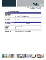
Page 14: ...aracteristics Micro controller Micro controller RISC 8 bits with Flash memory Programming Through serial link Through the air Download Over The Air RAM memory 2 Kbytes Flash memory 16 Kbytes Serial li...

Page 15: ...written authorization All Rights Reserved page 15 of 47 1vv0300826 Rev 3 14 01 2011 II 8 Ordering information Select the desired options from the list below to identify the appropriate Telit part numb...

Page 16: ...forbidden without Telit Communications S p A written authorization All Rights Reserved page 16 of 47 1vv0300826 Rev 3 14 01 2011 CHAPTER III MECHANICS AND CONNECTION III 1 Mechanical Characteristics...

Page 17: ...while RxD is for the data coming into the Modem The logic 1 is represented by signal between 3 and 15V DTR Stand By signal into the Modem Switches the Modem in Low Power Mode 1 15V to 3V or in Normal...

Page 18: ...n blinks each 5 seconds when receiving beacon Note In case of the S One stack green LED indicated transmission III 3 Cables Description for IP67 Casing The associated cable is connected to the termina...

Page 19: ...eceive Data 2 A or Rx Receive Data White Z or Tx Transmit Data 3 B or Rx Receive Data Brown Y or Tx Transmit Data 4 Y or Tx Transmit Data Yellow A or Rx Receive Data 5 DTR Green Open 6 RS232 422 485 O...

Page 20: ...dard firmware working in transparent or address secured mode M ONE protocol stack o Mesh Lite firmware allowing mesh networking refer to dedicated manual 5 for detailed explanation This Chapter is ded...

Page 21: ...a silent time at least equal to the serial time out In this case only AT and CR shall not be used Below is the complete list of the AT commands available on the M868 TinyPlus terminal Command Descrip...

Page 22: ...level 77dBm ATR Parameters reset ATR command resets all terminal s parameters to their default values Answer OK ATP Stand By Activation When serial stand by is set the ATP command put the terminal in...

Page 23: ...rames are addressed checked through a CRC and acknowledged Downloader over the air this is a specific communication protocol allowing re flashing of remote terminal Auto repeat mode this is a specific...

Page 24: ...l N 3 1 sends ABCD to 2 2 ABCD OK 1 ABCD 1 sends EFGH to 3 with a retry 3 EFGH OK 1 EFGH ACK 3 sends Hello as Broadcast 3 Hello 3 Hello 0 Hello Basic Illustration of Addressed Secured mode with LBT Te...

Page 25: ...erial parameters S22x registers correspond to the operating parameters S24x registers correspond to the stand by parameters S25x registers correspond to the network parameters Radio Configuration The...

Page 26: ...th 4 Sub Bands S206 value Band Frequency Sub Band 0 1f 868 868 6 MHz 2 1g 868 7 869 2 MHz 6 1i 869 4 869 65 MHz 8 1k 869 7 870 MHz Terminals must be on the same Sub Band to communicate The default val...

Page 27: ...2 1mW 3mW 8mW 0 1 1mW 3mW Radio Bit Rate 19 2 Kbps 38 4 Kbps S202 Value 0 1 2 3 1mW 3mW 8mW 25mW 0 1 2 3 1mW 3mW 8mW 25mW 0 1 2 3 1mW 3mW 8mW 25mW 0 1 1mW 3mW 5 Radio carrier length S204 This register...

Page 28: ...erial link type S215 Set the flow control type S216 After each modification in the serial settings the M868 TinyPlus will answer OK with the current configuration and the changes will be effective imm...

Page 29: ...te S210 part of this chapter For example for a 19200 bps baud rate the time to send 1 character 1 start bit 8 data bits 1 stop bit is 521 s giving a squared up timeout value of 2 ms You can set a high...

Page 30: ...S216 In all the modes the data coming from the serial link are stored in a buffer and then sent Thus it is necessary to have a flow control on the serial link to avoid a buffer overflow and the loss...

Page 31: ...ity The LBT sensitivity refers to the detected RF level over which the RF link is considered as occupied Value LBT Comment 0 OFF default no LBT 1 ON with high sensitivity LBT with detection for RF 87d...

Page 32: ...f you want to place more than one network in the same area use different radio channels and not different network numbers The default value is 0 2 Network Options S255 When running in Addressed and Se...

Page 33: ...35 terminals This bit has no effect if the header is ASCII Bit 2 0 The frames sent and received will be as follows 0x01 Data if this bit is set to 0 0x00 0x01 Data if this bit 5 is set to 1 ACK Bit 6...

Page 34: ...Band used Refer to III 4 Default 0 R W S201 Radio Baud Rate Indicates the radio link rate 0 4 8 Kbits s 1 9 6 Kbits s 2 19 2 Kbits s 3 38 4 Kbits s R W S202 Output Power Radio power output in milliwat...

Page 35: ...s s 2 ms 19200 bits s R W S212 Parity Serial Link Parity Type 1 None default 2 Even 3 Odd R W S213 Number of Stop bits Serial Link Stop Bits 1 bit default 2 bits R W S214 Serial Link Time Out Indicate...

Page 36: ...Number of retries in case of non Ack response to a message addressed secured mode mode or in case of non free radio link LBT Included between 0 and 255 255 means retry until success Default value 2 R...

Page 37: ...e Client ID 1 or not 0 Bit CR indicates whether the received frame ends with the Carriage Return character 0x0D 1 or not 0 Bit NH indicates whether the format in Transmission and in reception if the B...

Page 38: ...a Client Server configuration also called Star network where communications are able only between the Server and the Clients CLASSICAL CLIENT SERVER All Server Clients ATS220 9 ATS220 9 ATS220 9 ATS2...

Page 39: ...1vv0300826 Rev 3 14 01 2011 IV 6 Modems reflashing M868 TinyPlus terminals are re flashable through the serial link To reflash the modem switch off the power supply open the casing put the PROG switc...

Page 40: ...er device without the need of any hardware intervention on the remote device All steps of the process can be done from a local radio terminal connected to a computer Firmware or settings are sent thro...

Page 41: ...n A 1 m distance between two modems should be respected under 25 mW power output at least 2 m at 100 mW and 3 m at 500 mW The modems should be located as high and as free as possible so that a line of...

Page 42: ...32 mode by default it allows to directly connect it on a PC serial port To configure the terminal in RS422 or RS485 mode Go to Hayes Mode and configure S215 Register set to 2 for RS485 and to 1 for RS...

Page 43: ...MHz Terminal User Guide Reproduction forbidden without Telit Communications S p A written authorization All Rights Reserved page 43 of 47 1vv0300826 Rev 3 14 01 2011 V 3 ETSI 300 220 3 Version 1 3 1 s...

Page 44: ...TinyOne Plus 868MHz Terminal User Guide Reproduction forbidden without Telit Communications S p A written authorization All Rights Reserved page 44 of 47 1vv0300826 Rev 3 14 01 2011...

Page 45: ...TinyOne Plus 868MHz Terminal User Guide Reproduction forbidden without Telit Communications S p A written authorization All Rights Reserved page 45 of 47 1vv0300826 Rev 3 14 01 2011...

Page 46: ...25 3 dB 35 3 4 dB 50 5 8 dB Medium wall wood 40 4 6 dB 50 5 8 dB 70 10 12 dB Thick wall concrete 50 5 8 dB 60 9 11 dB 85 15 20 dB Armoured wall reinforced concrete 70 10 12 dB 80 12 15 dB 90 20 25 dB...

Page 47: ...e Plus 868MHz Terminal User Guide Reproduction forbidden without Telit Communications S p A written authorization All Rights Reserved page 47 of 47 1vv0300826 Rev 3 14 01 2011 V 5 Declarations of Comp...

Reviews: