background image


xE70-915 RF Module User Guide 

1VV0301106 

rev.3 – 2015-03-04 

Summary of Contents for xE70-915

Page 1: ...xE70 915 RF Module User Guide 1VV0301106 rev 3 2015 03 04...

Page 2: ...15 RF Module User Guide 1VV0301106 rev 3 2015 03 04 Reproduction forbidden without written authorization from Telit Communications S p A All Rights Reserved Page 2 of 34 APPLICABILITY TABLE PRODUCT LE...

Page 3: ...ve for Telit and its licensors certain exclusive rights for copyrighted material including the exclusive right to copy reproduce in any form distribute and make derivative works of the copyrighted mat...

Page 4: ...translated into any language or computer language in any form or by any means without prior written permission of Telit High Risk Materials Components units or third party products used in the produc...

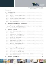
Page 5: ...2 1 1 915 MHz band Requirements 9 2 2 Other Regulatory Requirements 9 3 General Features 10 3 1 Main Functionalities 10 3 2 Software 10 3 3 Temperature Requirements 10 3 4 Mechanical Specifications 11...

Page 6: ...Soldering pad pattern 23 5 4 Solder paste 24 5 5 Placement 24 5 6 Soldering Profile RoHS Process 24 6 Board Mounting Recommendation 26 6 1 Electrical environment 26 6 2 Power supply decoupling on xE70...

Page 7: ...ty L LE70 915 FH Star Network xE70 915 is pin to pin compatible with LE NE and ME modules working at different frequencies in particular xE50 868 and xE70 868 xE70 915 is also pin to pin compatible wi...

Page 8: ...the users of our information 1 5 Text Conventions Danger This information MUST be followed or catastrophic equipment failure or bodily injury may occur Caution or Warning Alerts the user to important...

Page 9: ...cy hopping RF devices and gives the following requirements Frequency Band Channel spacing Maximum radiated power Hopping cycle 902 928 MHz 25 20dB BW 250kHz 1W 0 4s each 20s 0 4s each 20s 50 hop Freq...

Page 10: ...rectional link The digital part has the following functionalities Communication interface I O management Micro controller with embedded Telit Software Stack The RF part has the following functionaliti...

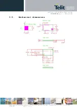
Page 11: ...4 3 4 Mechanical Specifications Size Rectangular 25 8 x 15 mm Height 3 mm Weight 1 7 g PCB thickness 0 8 mm Cover Mounted above SMD components for EMI reduction and automatic placement Dimensions 25 x...

Page 12: ...E70 915 RF Module User Guide 1VV0301106 rev 3 2015 03 04 Reproduction forbidden without written authorization from Telit Communications S p A All Rights Reserved Page 12 of 34 3 5 Mechanical dimension...

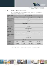
Page 13: ...under 50 impedance connected to RF port and default power register setting if nothing else stated Max limits apply over the entire operating range T 40 C to 85 C Vdd 2 3V to 3 6V and all channels Cha...

Page 14: ...902 MHz 928 MHz RF data rate 9 6 kbps 19 2 kbps 38 4 kbps 57 6 kbps Number of channels 50 Channel spacing 250 kHz First Channel 915 375 MHz Transmission Duty cycle 10 Modulation Format 2GFSK Technolo...

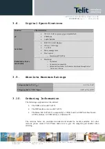
Page 15: ...e flashed o Customization capability o Embedded bootloader for firmware download through serial link or over the air 3 9 Absolute Maximum Ratings Voltage applied to Vcc VDD 0 3V to 3 6V Voltage applie...

Page 16: ...ev 3 2015 03 04 Reproduction forbidden without written authorization from Telit Communications S p A All Rights Reserved Page 16 of 34 Equipment and Part Number SMD Version B LE70 915 SMD DIP Version...

Page 17: ...ions S p A All Rights Reserved Page 17 of 34 4 Pin out and Signals Description 4 1 Module Pin out Top View CAUTION reserved pins must not be connected CAUTION In case you want to use in the same appli...

Page 18: ...GND Gnd Ground J16 PROG I TTL Signal for serial C flashing Active high with internal pull down J15 GND Gnd Ground J14 PDI_DATA I O TTL Program and Debug Interface DATA J13 GND Gnd Ground J12 GND Gnd G...

Page 19: ...ll Rights Reserved Page 19 of 34 J2 IO2_P I O TTL Logic I O N 2 with interrupt RX LED O TTL See reference document 2 Frequency Hopping Star Network Protocol Stack User Guide J1 IO1_P I O TTL Logic I O...

Page 20: ...ND 3 P1 J5 IO5_A 4 P2 J9 Status TX RX Reserved Pin 5 P3 J2 RX LED 6 P4 J1 TX LED 7 P5 J4 IO4_A 8 P6 J3 IO3_A 9 GND GND 10 VDD J25 VDD J2 11 PROG J16 PROG 12 RTS J22 RTS 13 CTS J24 CTS 14 RESET J23 RES...

Page 21: ...utput See reference document 2 for LE70 915 STANDBY Input signal which indicates to the module to switch to pre selected low power mode See reference document 2 for LE70 915 TX LED Output signal set t...

Page 22: ...All Rights Reserved Page 22 of 34 5 Process Information 5 1 Delivery xE70 915 modules are delivered in plastic tray packaging each tray including 50 units The dimensions of the tray are the following...

Page 23: ...ior to the reflow soldering process in order to prevent a popcorn effect After being submitted to the drying bake modules must be soldered on host boards within 168 hours Also it must be noted that du...

Page 24: ...c and made of 95 5 of SN 4 of Ag and 0 5 of Cu The recommended solder paste height is 180 m 5 5 Placement The xE70 915 module can be automatically placed on host boards by pick and place machines like...

Page 25: ...served Page 25 of 34 The barcode label located on the module shield is able to withstand the reflow temperature CAUTION It must also be noted that if the host board is submitted to a wave soldering af...

Page 26: ...ongly decrease module performances Therefore it is recommended to put a metallic shield covering DC conversion function Switching components circuits especially RS 232 TTL interface circuit power supp...

Page 27: ...achieve a good RF layout It is recommended to fill all unused PCB area around the module with ground plane The radio module ground pin must be connected to solid ground plane If the ground plane is o...

Page 28: ...the antenna or connector must be 50 ohms following the tables below Ground lines should be connected to the ground plane with as many vias as possible but not too close to the signal line PCB materia...

Page 29: ...3 2015 03 04 Reproduction forbidden without written authorization from Telit Communications S p A All Rights Reserved Page 29 of 34 6 5 xE70 868 915 Interfacing Example of a full RS 232 connection bet...

Page 30: ...e 1VV0301106 rev 3 2015 03 04 Reproduction forbidden without written authorization from Telit Communications S p A All Rights Reserved Page 30 of 34 Example of minimum connections for communication be...

Page 31: ...Module User Guide 1VV0301106 rev 3 2015 03 04 Reproduction forbidden without written authorization from Telit Communications S p A All Rights Reserved Page 31 of 34 Example for sensor connection with...

Page 32: ...to the following two conditions 1 this device may not cause interference and 2 this device must accept any interference including interference that may cause undesired operation of the device Le pr se...

Page 33: ...If this equipment does cause harmful interference to radio or television reception which can be determined by turning the equipment off and on the user is encouraged to try to correct the interference...

Page 34: ...l Rights Reserved Page 47 of 50 module d mission du mot Contient ou d une formulation similaire exprimant le m me sens comme suit Contains FCC ID RI7LE70FH Contains IC 5131A LE70FH 7 6 CAN ICES 3 B NM...

Page 35: ...to the security and fire prevention regulations The product has to be handled with care avoiding any contact with the pins because electrostatic discharges may damage the product itself The system int...

Page 36: ...ETSI European Telecommunication Standard Institute FCC FH GFSK Federal Communications Commission Frequency Hopping Gaussian Frequency Shift Keying I Input ISM Industrial Scientific and Medical kB Kilo...

Page 37: ...ges 0 2013 10 11 First Release 1 2014 04 02 Updated LE70 915 Demo Kit content 2 2014 07 21 Corrected partname for L1 on page 26 updated sensitivity and current consumption values 3 2015 03 04 Updated...

Reviews: