background image

330235

Rev. 02 (9--01)

Service Manual

6100 G/LP

Summary of Contents for 6100 G/LP

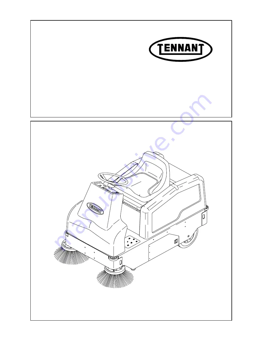
Page 1: ...330235 Rev 02 9 01 Service Manual 6100 G LP ...

Page 2: ...ment and replacement steering adjustment and replacement Sweeping Hopper repair replacement brush repair replacement skirt seal repair replacement and sweeping troubleshooting Electrical Battery maintenance and replacement electrical schematics and electrical troubleshooting Hydraulics Valve replacement motor replacement repair cylinder replacement repair pump replacement repair filter replacement...

Page 3: ... CHART 1 8 PUSHING TOWING AND TRANSPORTING THE MACHINE 1 10 PUSHING OR TOWING THE MACHINE 1 10 TRANSPORTING THE MACHINE 1 10 MACHINE JACKING 1 12 STORING MACHINE 1 12 HARDWARE INFORMATION 1 13 STANDARD BOLT TORQUE CHART 1 13 METRIC BOLT TORQUE CHART 1 13 BOLT IDENTIFICATION 1 13 THREAD SEALANT AND LOCKING COMPOUNDS 1 13 HYDRAULIC FITTING INFORMATION 1 14 HYDRAULIC TAPERED PIPE FITTING NPT TORQUE C...

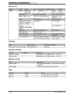
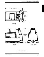
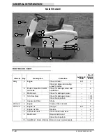
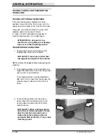
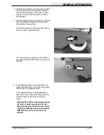
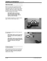
Page 4: ...GENERAL INFORMATION 1 2 6100 G LP 330235 9 01 ...

Page 5: ...eration 3 When starting machine Keep foot on brake and directional pedal in neutral 4 When using machine Use brakes to stop machine Go slowly on inclines and slippery surfaces Use care when reversing machine Do not carry riders on machine Always follow safety and traffic rules Report machine damage or faulty operation immediately 5 Before leaving or servicing machine Stop on level surface Set park...

Page 6: ...on the machine in the locations indicated If these or any labels become damaged or illegible install a new label in its place FOR SAFETY LABEL LOCATED ON THE SIDE OF THE OPERATOR COMPARTMENT FLYING DEBRIS LABEL LOCATED ABOVE HOPPER 352182 EMISSIONS LABEL Located Below The Operator s Seat ...

Page 7: ...m 22 in Sweeping path width with one side brush 762 mm 30 in Sweeping path width with two side brushes 965 mm 38 in Main sweeping brush pattern width 50 mm 2 in Hopper weight capacity 90 kg 200 lb Hopper volume capacity 85 L 3 cu ft Dust filter area 3 2 sq m 34 sq ft GVWR 2041 kg 1009 lb GENERAL MACHINE PERFORMANCE Item Measure Maximum forward speed 8 km h 5 mph Maximum reverse speed 4 8 km h 3 mp...

Page 8: ...d Firing order 2200 rpm gov 2200 rpm gov Spark plug gap Valve clearance cold Engine lubricating oil with filter 1 mm 0 043 in 0 145 to 0 185 mm 0 0057 to 0 0072 in intake and exhaust 1 20 L 1 27 qt 10W30 SAE SG SH STEERING Type Power source Emergency steering Front wheel manual controlled Manual steering Manual HYDRAULIC SYSTEM System Capacity Fluid Type Hydraulic reservoir TENNANT part no 65869 a...

Page 9: ...GENERAL INFORMATION 1 7 6100 G LP 330235 9 01 TOP VIEW SIDE VIEW 1524 mm 60 in 813 mm 32 in 1270 mm 50 in FRONT VIEW 352185 MACHINE DIMENSIONS ...

Page 10: ...6 Brush compartment skirts and seals Check for damage wear and adjustment 6 4 Main brush Check for damage or wear 1 5 Side brush es Check for damage or wear 1 2 Check brush pattern 1 2 7 Hopper dust filter Shake 1 25 Hours 3 Engine Clean air filter element 1 50 Hours 3 Engine oil Change EO 2 3 Engine air filter Replace 2 2 Vacuum fan belt Check tension and wear 2 4 Main brush Rotate end for end 1 ...

Page 11: ...wl 1 11 Brake Check adjustment 1 13 Side brush es Check pivot adjustment 1 2 2 Vacuum fan belt Check tension and wear 1 3 Main brush belt Check for wear 1 300 Hours 13 Side brush motor s Check motor brushes 1 800 Hours Hydraulic fluid reservoir Replace filler cap 3 y Replace suction strainer 3 Change hydraulic fluid HYDO 3 Hydraulic fluid filter HChange filter element 3 Hydraulic hoses Check for w...

Page 12: ... the machine at the loading edge of the truck or trailer FOR SAFETY Use truck or trailer that will support the weight of the machine NOTE Empty the hopper before transporting the machine 2 If the loading surface is not horizontal or is higher than 380 mm 15 in from the ground use a winch to load machine If the loading surface is horizontal AND is 380 mm 15 in or less from the ground the machine ma...

Page 13: ...re the holes in the front of the machine frame The rear tie down locations are the holes in the sides of the machine frame near the rear bumper 6 If the loading surface is not horizontal or is higher than 380 mm 15 in from the ground use a winch to unload machine If the loading surface is horizontal AND is 380 mm 15 in or less from the ground the machine may be driven off the truck or trailer FOR ...

Page 14: ...on level surface set parking brake turn off machine and remove key The front jacking locations are on the flat bottom edge of the front of the machine frame The rear jacking locations are on the corners of the rear frame FOR SAFETY When servicing machine block machine tires before jacking up machine FOR SAFETY When servicing machine jack up machine at designated locations only Block machine up wit...

Page 15: ...80 291 380 313 407 424 552 1 00 in 500 650 678 881 757 984 1026 1334 NOTE Decrease torque by 20 when using a thread lubricant METRIC BOLT TORQUE CHART Thread Size Class 8 8 Torque ft lb _Nm Class 10 9 Torque ft lb Nm M4 2 3 3 4 M5 4 5 6 8 M6 7 9 10 14 M8 18 24 25 34 M10 32 43 47 64 M12 58 79 83 112 M14 94 127 133 180 M16 144 195 196 265 M20 260 352 336 455 M24 470 637 664 900 NOTE Decrease torque ...

Page 16: ... 9 ft lb 12 Nm 0 38 0 56 18 20 ft lb 27 Nm 0 50 0 75 16 30 ft lb 41 Nm 0 62 0 88 14 40 ft lb 54 Nm 0 75 1 12 12 70 ft lb 95 Nm 1 0 1 31 12 90 ft lb 122 Nm HYDRAULIC O RING FITTING TORQUE CHART Tube O D in Thread Size Minimum Torque Maximum Torque 0 25 0 44 20 6 ft lb 8 Nm 9 ft lb 12 Nm 0 38 0 56 18 13 ft lb 18 Nm 20 ft lb 27 Nm 10 ft lb 14 Nm 12 ft lb 16 Nm 0 50 0 75 16 20 ft lb 27 Nm 30 ft lb 41 ...

Page 17: ...E AND WHEEL 2 14 TO INSTALL FRONT TIRE AND WHEEL 2 17 TO REPLACE FRONT WHEEL DRIVE CHAIN 2 20 TO REPLACE FRONT WHEEL HUB BEARINGS 2 23 TO ADJUST STEERING CHAIN 2 24 TO REPLACE STEERING CHAIN 2 26 TO REPLACE STEERING HOUSING BEARINGS 2 29 TO REPLACE STEERING U JOINT 2 35 TO REPLACE SMALL STEERING SPROCKET 2 37 TO REPLACE LARGE STEERING SPROCKET 2 40 TO REPLACE FRONT WHEEL HOUSING NEEDLE BEARING THR...

Page 18: ...CHASSIS 2 2 6100 G LP 330235 9 00 ...

Page 19: ...CHASSIS 2 3 6100 G LP 330235 9 00 INTRODUCTION This section includes information on the main chassis related components for example the seat steering brakes and tires ...

Page 20: ...ke and parking brake are each actuated with a foot pedal TO ADJUST SERVICE BRAKE FOR SAFETY Before Leaving Or Servicing Machine Stop On Level Surface place blocks in front and back of back wheels 1 If the service brake pedal has excessive movement before the brake is activated the service brake needs to be adjusted 2 Go under the front of the machine and locate the disc brake caliper assembly 3 Re...

Page 21: ...ount of movement before the brakes are engaged If this is the case the adjustment is complete if not repeat the previous step NOTE If the lever does not reach the next hole loosen the two screws holding the small lever to the caliper The lever pin can now be moved up to the next hole Retighten the hardware TO ADJUST PARKING BRAKE The parking brake adjustment is made at the same time as the service...

Page 22: ... Stop On Level Surface Set Parking Brake 1 Remove the front wheel assembly See TO REMOVE FRONT TIRE AND WHEEL instructions in this section 2 Remove the tension spring from the brake caliper lever and wheel housing 3 Remove the nuts from the shoulder screws holding the brake caliper to the wheel housing ...

Page 23: ...g Note the orientation of the caliper assembly on the wheel housing 5 Remove the two shoulder screws from the caliper assembly 6 Pull the two brake pads out of the caliper assembly Note the orientation of the pads 7 Install the new pads into the caliper assembly in the same orientation ...

Page 24: ...oles on the wheel housing Reinstall the two nyloc nuts and tighten to 18 24 Nm 15 20 ft lb Make sure the caliper free floats after the screws are tightened 10 Reinstall the tension spring onto the brake caliper lever and wheel housing 11 Reinstall the front tire and wheel assembly See TO INSTALL FRONT TIRE AND WHEEL instructions in this section 12 Operate the machine and check the brakes for prope...

Page 25: ...ires are free wheeling and have no braking capabilities TO REMOVE REAR TIRE ASSEMBLY FOR SAFETY Before Leaving Or Servicing Machine Stop On Level Surface Set Parking Brake 1 Remove the debris hopper from the rear of the machine 2 Jack up the machine at the rear jack point Place a jack stand under the machine frame ...

Page 26: ...te the large nyloc nut and washer holding the rear wheel axle to the machine Remove the nyloc nut and washer 4 Support the rear wheel and remove the axle shaft 5 Remove the rear tire assembly from the machine 6 Remove the three hex screws and nuts holding the wheel hub to the tire assembly ...

Page 27: ...CHASSIS 2 11 6100 G LP 330235 9 00 7 Remove the hub assembly from the tire assembly ...

Page 28: ... then through the wheel Install the nuts Center the hub on the wheel Tighten the nuts to 18 24 Nm 15 20 ft lb 2 Install the tire and hub assembly into the machine with the hub positioned on the inside of the machine frame 3 Hold the wheel in position and install the axle shaft from to outside of the machine frame Note the D shape of the frame mount hole and the D on the axle shaft Line these two u...

Page 29: ...side of the machine frame and install the washer and nyloc nut Tighten to 37 48 Nm 26 34 ft lb 5 Spin the tire assembly to make sure it turns freely 6 Remove the jack stand and lower the machine to the floor 7 Operate the machine for proper operation ...

Page 30: ...a steering wheel which turns a chain that is connected to the front wheel housing The front wheel housing turns on a large bearing and rubber seal TO REMOVE FRONT TIRE AND WHEEL FOR SAFETY Before Leaving Or Servicing Machine Stop On Level Surface place blocks in front and back of the rear tires 1 Jack up the front of the machine at the jack point Install jack stands under the machine frame 2 Remov...

Page 31: ...nt tire until the master link is visible at the bottom of the drive sprocket Remove the master link from the drive chain Make sure to retain the four small O rings from behind the master link clip NOTE Try to keep the chain on the upper sprocket when removing the wheel 5 Remove the large nut and washer from the wheel axle 6 Support the front drive wheel Remove the axle from the front wheel ...

Page 32: ...emove the front drive wheel from the machine 8 Remove the four screws holding the brake disc to the front hub assembly Make sure to retain the four steel sleeves Pull the brake disc off the hub 9 Remove the three wheel nuts holding the tire to the front hub 10 Remove the tire assembly from the hub ...

Page 33: ...ll the three wheel nuts and tighten to 64 83 Nm 47 61 ft lb 2 Reinstall the brake disc onto the front hub assembly NOTE Place a small amount of grease in the ID of the brake disc The hub of the brake disc is positioned toward the tire 3 Reinstall the four hex screws and steel sleeves Use red loctite 271 on the threads of the screws and tighten to 18 24 Nm 15 20 ft lb Tighten these screws in a cris...

Page 34: ...tallation of the assembly into the wheel support 5 Line up the wheel hub bearings with the mount holes on the wheel support 6 Push the wheel axle from the right hand side into the wheel housing and wheel hub Note the D shape of the wheel support mount hole and the D on the axle shaft Line these two up and push the axle all the way into the mount hole 7 Install the washer and nyloc nut onto the axl...

Page 35: ... small O rings are in place behind the master link clip 9 Push the hydraulic motor up until the drive chain is tight 1 8 inch at mid point Tighten nuts to 18 24 Nm 15 20 ft lb 10 Reinstall the drive chain guard and tighten the two nuts to 18 24 Nm 15 20 ft lb 11 Remove the jack stands and lower the machine to the floor Operate the machine and check for proper operation ...

Page 36: ...front and back of the rear tires 1 Jack up the front of the machine at the jack point Install jack stands under the machine frame 2 Remove the two nuts holding the chain guard to the wheel support Remove the chain guard 3 Loosen the three nuts holding the hydraulic drive motor to the wheel support Let the motor drop down so the drive chain has some slack ...

Page 37: ...lip 5 Pull the old chain off the drive motor sprocket and drive wheel sprocket Remove the old drive chain from the machine 6 Reinstall the new drive chain around the drive sprocket on the drive motor and front wheel assembly Reinstall the master link Make sure the four small O rings are in place behind the master link clip 7 Push the hydraulic drive motor up until the chain is tight 1 8 inch at mi...

Page 38: ...330235 9 00 8 Reinstall the drive chain guard and tighten the two nuts to 18 24 Nm 15 20 ft lb 9 Remove the jack stands and lower the machine to the floor Operate the machine and check the new drive chain for proper operation ...

Page 39: ...embly See TO REMOVE FRONT TIRE AND WHEEL instructions in this section 2 Use a long screw driver or punch to hammer the two bearings out of the front hub assembly Discard the old bearings 3 Use an arbor press to install the new bearings into the front hub Push the bearings down until they are seated flush against the housing 4 Reinstall the front wheel assembly See TO INSTALL FRONT TIRE AND WHEEL i...

Page 40: ... of the machine at the jack point Install jack stands under the machine frame 2 Go to the operators compartment and locate the two hex screws holding the steering bearing housing to the machine frame Loosen the two screws 3 Turn the steering wheel all the way to the left and then to the right Find the point in the rotation where the steering chain is the most tight ...

Page 41: ...ng forward in the slots This will remove any excess slack in the steering chain Tighten the two hex screws to 37 48 Nm 26 34 ft lb 5 Remove the jack stands and lower the machine to the floor Operate the machine and check the steering chain for proper operation ...

Page 42: ...ack of the rear tires 1 Jack up the front of the machine at the jack point Install jack stands under the machine frame 2 Turn the steering wheel all the way to the left 3 Go to the operators compartment and locate the two hex screws holding the steering bearing housing to the machine frame Loosen the two screws and push the bearing housing back in the slots ...

Page 43: ...teering chain Remove the master link and steering chain 6 Position the new steering chain around both the large steering sprocket and small sprocket Install a new master link in the new chain 7 Turn the steering wheel all the way to the left and then to the right Find the point in the rotation where the steering chain is the most tight ...

Page 44: ...ng forward in the slots This will remove any excess slack in the steering chain Tighten the two hex screws to 37 48 Nm 26 34 ft lb 9 Remove the jack stands and lower the machine to the floor Operate the machine and check the steering chain for proper operation ...

Page 45: ...ine Stop On Level Surface Set Parking Brake 1 Jack up the front of the machine at the jack point Install jack stands under the machine frame 2 Turn the steering wheel all the way to the left 3 Go to the operators compartment and locate the steering U joint Loosen the two set screws on the top of the steering U joint ...

Page 46: ... joint 5 Remove the two hex screws holding the steering bearing housing to the machine frame Push the bearing housing back in the slots 6 Go under the machine and locate the small steering chain sprocket 7 Locate the master link on the steering chain Remove the master link and steering chain from the small steering sprocket ...

Page 47: ...e and retain the U joint and square key 10 Loosen the set screw holding the small steering sprocket to the bottom of the short steering shaft Remove and retain small sprocket and woodruff key 11 Use an arbor press to press the short steering shaft and two bearings out of the housing Discard the bearings Retain the short shaft Note the orientation of the shaft in the housing ...

Page 48: ...g 13 Use the arbor press to install the short steering shaft into the new bearings 14 Reinstall the small steering sprocket and woodruff key on the bottom of the steering housing Tighten the set screws tight 15 Reinstall the U joint and square key on the top of the steering housing Tighten the set screws tight ...

Page 49: ...ring shaft and steering wheel into the top of the steering U joint Tighten the set screws tight 18 Go under the machine and reinstall the steering chain around the small steering sprocket Reinstall the master link 19 Turn the steering wheel all the way to the left and then to the right Find the point in the rotation where the steering chain is the most tight ...

Page 50: ...ng forward in the slots This will remove any excess slack in the steering chain Tighten the two hex screws to 37 48 Nm 26 34 ft lb 21 Remove the jack stands and lower the machine to the floor Operate the machine and check the steering chain for proper operation ...

Page 51: ...t Parking Brake 1 Jack up the front of the machine at the jack point Install jack stands under the machine frame 2 Go to the operators compartment and locate the steering U joint Loosen the two set screws on the top of the steering U joint 3 Pull the steering wheel and long steering shaft up and out of the top of the steering U joint ...

Page 52: ... discard the U joint and square key 5 Install the new U joint and square key on the top of the steering housing Tighten the set screws tight 6 Position the long steering shaft and steering wheel into the top of the steering U joint Tighten the set screws tight 7 Operate the machine and check the steering U joint for proper operation ...

Page 53: ...up the front of the machine at the jack point Install jack stands under the machine frame 2 Turn the steering wheel all the way to the left 3 Go to the operators compartment and locate the two hex screws holding the steering bearing housing to the machine frame Loosen the two screws and push the bearing housing back in the slots This will loosen the steering chain ...

Page 54: ... steering chain 6 Loosen the set screw holding the small steering sprocket to the bottom of the short steering shaft Remove and discard the small sprocket Retain the woodruff key 7 Install the new small sprocket and woodruff key onto the steering shaft The teeth of the new sprocket face down Position the sprocket in the same location as the old one Tighten the two set screws tight ...

Page 55: ...en to the right Find the point in the rotation where the steering chain is the most tight 10 Push the bearing housing forward in the slots This will remove any excess slack in the steering chain Tighten the two hex screws to 37 48 Nm 26 34 ft lb 11 Remove the jack stands and lower the machine to the floor Operate the machine and check the steering for proper operation ...

Page 56: ...r tires 1 Jack up the front of the machine at the jack point Install jack stands under the machine frame 2 Turn the steering wheel all the way to the left 3 Go to the operators compartment and locate the two hex screws holding the steering bearing housing to the machine frame Loosen the two screws and push the bearing housing back in the slots This will loosen the steering chain ...

Page 57: ...FRONT TIRE AND WHEEL instructions in this section 6 Go under the machine and locate the short brake rod coming through the center of the wheel support bearing assembly Disconnect the clevis end of the short brake cable where it attaches to the brake lever 7 Remove the four hex screws holding the wheel support and large sprocket to the pivot bearing assembly Drop the wheel support and large sprocke...

Page 58: ...ing pin on the wheel support is inserted in the locating pin hole in the new sprocket 10 Position the wheel support and sprocket assembly into the machine Line up the mount holes in the wheel support and sprocket with the threaded holes in the bottom of the pivot bearing assembly Reinstall the four screws and tighten to 64 83 Nm 47 61 ft lb 11 Reconnect the short brake rod to the brake lever ...

Page 59: ...14 Turn the steering wheel all the way to the left and then to the right Find the point in the rotation where the steering chain is the most tight 15 Push the bearing housing forward in the slots This will remove any excess slack in the steering chain Tighten the two hex screws to 37 48 Nm 26 34 ft lb 16 Remove the jack stands and lower the machine to the floor Operate the machine and check the st...

Page 60: ...ck of the rear tires 1 Jack up the front of the machine at the jack point Install jack stands under the machine frame 2 Turn the steering wheel all the way to the left 3 Go to the operators compartment and locate the two hex screws holding the steering bearing housing to the machine frame Loosen the two screws and push the bearing housing back in the slots This will loosen the steering chain ...

Page 61: ... 5 Mark disconnect and plug the hydraulic hoses leading to the drive motor 6 Go to the operators compartment and locate the clevis pin holding the brake pedal assembly to the floor plate Remove the clevis pin and tension spring from the brake pedal 7 Pull the brake pedal up and disconnect the clevis end of the short brake rod where it attaches to the brake pedal assembly ...

Page 62: ...drive assembly in the machine Lower the drive assembly down and out of the machine 9 Remove the small thread roller screw holding the castle nut to the pivot shaft Remove the castle nut and flat washer 10 Pull the cone bearing out of the swivel plate 11 Pull the swivel plate off the swivel plate weldment Make sure to retain the rubber seal ring ...

Page 63: ...sher Install the second thrust washer on top of the needle bearing 15 Reinstall the swivel plate onto the swivel plate weldment NOTE Make sure the rubber seal ring is in place on the swivel plate before installing 16 Reinstall the cone bearing in the swivel plate Grease the bearing if needed 17 Reinstall the large flat washer and castle nut Tighten to 37 48 Nm 26 34 ft lb Reinstall the small threa...

Page 64: ...ame Reinstall the four button head screws and tighten to 64 83 Nm 47 61 ft lb Make sure the drive motor is facing the front of the machine 20 Reinstall the steering chain onto both steering sprockets Reinstall the master link 21 Go back to the operators compartment Push the steering housing forward in the slots This will remove any slack in the steering chain Tighten the two hex screws to 37 48 Nm...

Page 65: ...ydraulic hoses to the drive motor 23 Reconnect the short brake rod to the brake pedal 24 Reinstall the brake pedal and clevis pin 25 Remove the jack stands and lower the machine to the floor Operate the machine and check the steering for proper operation ...

Page 66: ...e rear tires 1 Jack up the front of the machine at the jack point Install jack stands under the machine frame 2 Turn the steering wheel all the way to the left 3 Go to the operators compartment and locate the two hex screws holding the steering bearing housing to the machine frame Loosen the two screws and push the bearing housing back in the slots This will loosen the steering chain ...

Page 67: ... 5 Mark disconnect and plug the hydraulic hoses leading to the drive motor 6 Go to the operators compartment and locate the clevis pin holding the brake pedal assembly to the floor plate Remove the clevis pin and tension spring from the brake pedal 7 Pull the brake pedal up and disconnect the clevis end of the short brake rod where it attaches to the brake pedal assembly ...

Page 68: ...move the small thread roller screw holding the castle nut to the pivot shaft Remove the castle nut and flat washer 10 Pull the cone bearing out of the swivel plate 11 Grease the new cone bearing Reinstall the cone bearing into the swivel plate 12 Reinstall the large flat washer and castle nut Tighten to 37 48 Nm 26 34 ft lb Reinstall the small thread roller into the cross hole Back off the castle ...

Page 69: ...ame Reinstall the four button head screws and tighten to 64 83 Nm 47 61 ft lb Make sure the drive motor is facing the front of the machine 15 Reinstall the steering chain onto both steering sprockets Reinstall the master link 16 Go back to the operators compartment Push the steering housing forward in the slots This will remove any slack in the steering chain Tighten the two hex screws to 37 48 Nm...

Page 70: ...ydraulic hoses to the drive motor 18 Reconnect the short brake rod to the brake pedal 19 Reinstall the brake pedal and clevis pin 20 Remove the jack stands and lower the machine to the floor Operate the machine and check the steering for proper operation ...

Page 71: ...ervicing Machine Stop On Level Surface place blocks in front and back of the rear tires 1 Check the forward and reverse speeds of the model 6100G LP The forward speed should be 5 mph 5 mph The reverse speed should be 3 mph 5 mph If either speed needs to be adjusted go to the next step 2 Use the hex screw on the left back corner of the directional pedal to adjust the reverse speed 3 To adjust the f...

Page 72: ...CHASSIS 2 56 6100 G LP 330235 9 00 ...

Page 73: ...CE MAIN BRUSH IDLER PLUG BEARING 3 37 TO REPLACE MAIN BRUSH DRIVE PLUG BEARINGS 3 40 TO REPLACE MAIN BRUSH DRIVE BELT IDLER PULLEY 3 45 SIDE BRUSH 3 48 TO REPLACE SIDE BRUSH 3 49 SIDE BRUSH GUARD 3 51 SIDE BRUSH PIVOT 3 51 TO REPLACE SIDE BRUSH LIFT CABLE 3 52 Page SKIRTS AND SEALS 3 54 REAR SKIRT 3 54 SIDE SKIRTS 3 55 TO ADJUST SIDE SKIRTS 3 55 LARGE DEBRIS TRAP SKIRT 3 57 TO ADJUST FRONT FLAP SK...

Page 74: ...SWEEPING 3 2 6100 G LP 330235 9 00 ...

Page 75: ...s section includes information on the sweeping operation of the model 6100G LP The side brush sweeps debris in front of the machine and the main brush sweeps the debris into the hopper The vacuum fan pulls air from the hopper and through the dust filter ...

Page 76: ... machine under the battery compartment The hopper rolls in and out of position and rests in grooves that hold the hopper in place The hopper is held in operating position with a retaining clip NOTE Check that the hopper retaining clip is securely in place each time before operating machine ...

Page 77: ...rvicing Machine Stop On Level Surface Set Parking Brake 1 Go to the back of the machine 2 Grasp the hopper retainer clip Turn the retainer clip out of the way of the hopper lip 3 Grasp the hopper handle Pull up slightly then pull out on the hopper 4 Remove the hopper from the machine ...

Page 78: ...Before Leaving Or Servicing Machine Stop On Level Surface Set Parking Brake 1 Position the hopper into the back of the machine 2 Push the hopper in until it is flush with the back of the machine frame 3 Rotate the retainer clip down to lock the hopper in the machine ...

Page 79: ...r switch to the Filter shaker position D TAPPING Remove the filter and tap the filter gently on a flat surface with the dirty side down Do not damage the edges of the filter element and seals or the filter will not seat properly in the filter frame D AIR Blow air through the dust filter opposite the direction of the arrows This may be done with the dust filter in the machine Always wear eye protec...

Page 80: ...PPER DUST FILTER FOR SAFETY Before Leaving Or Servicing Machine Stop On Level Surface Set Parking Brake 1 Remove the debris hopper from the machine 2 Un latch the two filter pivot latches at the rear of the machine 3 Let the hooper filter pivot down ...

Page 81: ...wires 5 Remove the filter from the filter tray 6 Pull back on the tension spring located on the shaker assembly Cut the plastic ties holding the shaker to the filter 7 Remove the filter shaker assembly from the filter 8 Install the filter shaker assembly onto the new filter Make sure the pin on the shaker assembly is inserted in the hole in the filter shaker comb ...

Page 82: ...roperly the edge of the shaker should be between the filter and the filter seal 10 Reinstall the filter assembly into the filter tray 11 Reconnect the wires to the filter shaker 12 Pivot the filter tray up and re latch the latches 13 Reinstall the debris hopper and lock the retainer bracket ...

Page 83: ...ain brush in the lowered position Rotate the main brush end for end after every 50 hours of operation for maximum brush life and best sweeping performance Replace the main brush when the remaining bristles measure 25 mm 1 in in length TO REPLACE MAIN BRUSH FOR SAFETY Before Leaving Or Servicing Machine Stop On Level Surface Set Parking Brake 1 Stop the machine set the parking brake and turn the ma...

Page 84: ...sh idler arm assembly 4 Grasp the main brush pull it off the brush drive plug and out of the main brush compartment 5 Put the new or rotated end for end main brush on the floor next to the access door 6 Slide the main brush onto the drive plug Rotate the brush until it engages the drive plug and push it all the way onto the plug ...

Page 85: ...9 00 7 Check that the recirculation skirt is tucked in behind the frame 8 Slide the main brush idler arm plug onto the main brush 9 Secure the idler arm on the bolts Hand tighten the mounting knobs 10 Close the main brush access door ...

Page 86: ...sh and main brush and position the main brush over the chalked area 3 Start and lower the main brush for 15 to 20 seconds while keeping a foot on the brakes to keep the machine from moving NOTE If chalk or other material is not available allow the brushes to spin on the floor for two minutes A polish mark will remain on the floor 4 Raise the main brush 5 Drive the machine off the test area ...

Page 87: ...system have been replaced If the main brush pattern is tapered more than 15 mm 0 5 in on one end than the other adjust the taper as follows 1 Loosen the brush shaft bearing bracket mounting bolt and the idler arm securing head 2 Allow the brush to operate and float into position for approximately 30 seconds 3 Tighten the adjustment bolt and idler arm securing knob 4 Check the main brush pattern an...

Page 88: ...n on the belts The tension is set manually WARNING Moving belt Keep away TO REPLACE MAIN BRUSH DRIVE BELT FOR SAFETY Before Leaving Or Servicing Machine Stop On Level Surface Set Parking Brake 1 Remove the right hand machine panel 2 Remove the four screws holding the right hand brush door to the machine frame Remove the right hand side brush door ...

Page 89: ...lding the vacuum fan housing to the machine frame 4 Push the vacuum fan assembly forward in the slots to loosen the vacuum fan V belt 5 Remove the vacuum fan V belt from the two groove jackshaft sheave 6 Locate the main brush drive belt idler pulley between the jackshaft drive pulley and the larger brush pulley ...

Page 90: ...he main brush drive belt from the two remaining pulleys Remove and discard the old V belt belt 10 Position the new main brush drive belt onto the jackshaft and brush drive pulleys 11 Move the idler pulley forward in the slot until the belt is tight Tighten the hex nut to 18 24 Nm 15 20 ft lb 12 Install the vacuum fan V belt over both pulleys ...

Page 91: ...n the V belt The correct tension is when the belt deflects 8 38 mm 0 33 in from a force of 42 kg 90 to 95 lb at belt midpoint Tighten the screws hand tight 14 Reinstall the right hand machine cover 15 Reinstall the right hand side brush door 16 Operate the machine and check the main brush for proper operation ...

Page 92: ...eaving Or Servicing Machine Stop On Level Surface Set Parking Brake 1 Open the seat support and engage the prop rod 2 Remove the main brush See TO REPLACE MAIN BRUSH instructions in this section 3 Locate the main brush jackshaft belt tension idler pulley mount plate beside the machine battery ...

Page 93: ... V belt tension bolt to lower the idler pulley mount plate down This will loosen the tension on the jack shaft center V belt 6 Remove the V belt from the engine sheave idler sheaves and main jack shaft sheave Remove the V belt from the machine 7 Install the new V belt onto the engine sheave idler sheaves and jack shaft sheave ...

Page 94: ...ey mount plate up until the new V belt is tight Tighten the two nuts to 18 24 Nm 15 20 ft lb 9 Reinstall the main brush See TO REPLACE MAIN BRUSH instructions in this section 10 Disengage the seat rod and close the seat assembly 11 Operate the machine and check the main brush for proper operation ...

Page 95: ...Open the seat support and engage the prop rod 2 Locate the main brush jackshaft belt tension idler pulley mount plate beside the machine battery 3 Loosen the nuts holding the jackshaft belt idler mount plate to the main engine pulley plate 4 Use the V belt tension bolt to lower the idler pulley mount plate down This will loosen the tension on the jack shaft center V belt ...

Page 96: ... remove the main brush See TO REPLACE MAIN BRUSH instructions in this section 7 Locate the main brush jackshaft V belt sheave in the brush compartment area Loosen the two set screws Remove the sheave from the jackshaft Retain the square key 8 Loosen the set screws on the bearing lock collar Use a hammer and punch to knock the collar loose from the bearing race ...

Page 97: ...t 10 Remove the outer bearing flange from the mount bracket 11 Pull the inner bearing off the jackshaft 12 Install the new bearing onto the main brush jackshaft Make sure the lock collar is installed on the shaft first 13 Position the outer bearing flange onto the mount bracket Reinstall the hardware Leave loose for now ...

Page 98: ...the bearing lock collar onto the bearing race Hand tighten the collar set screw tight 16 Reinstall the sheave onto the end of the jackshaft Make sure the square key is in place on the jackshaft Position the sheave so the face is flush with the end of the shaft Hand tighten the two sheave set screws tight 17 Position the V belt over the jack shaft sheave idler sheaves and engine sheave ...

Page 99: ...on bolt to pull up on the idler arm to tighten the V belt Tighten the two nuts to 18 24 Nm 15 20 ft lb 19 Reinstall the main brush See TO REPLACE MAIN BRUSH instructions in this section 20 Start the machine and operate the main brush Check for proper operation ...

Page 100: ...CE MAIN BRUSH JACKSHAFT OUTER BEARING FOR SAFETY Before Leaving Or Servicing Machine Stop On Level Surface Set Parking Brake 1 Open the seat support and engage the prop rod 2 Remove the right hand machine panel 3 Remove the right hand brush door ...

Page 101: ...t plate to the main engine pulley plate 6 Use the V belt tension bolt to drop the idler pulley mount plate down to loosen the tension on the main brush center V belt 7 Remove the V belt from the engine sheave idler sheaves and main brush jackshaft sheave 8 Open the left hand brush door and remove the main brush See TO REPLACE MAIN BRUSH instructions in this section ...

Page 102: ...h to knock the collars loose from the bearing races 10 Go to the right rear corner of the machine and loosen the four hex screws holding the vacuum fan housing to the machine frame 11 Push the vacuum fan assembly forward in the slots to loosen the vacuum fan V belt 12 Remove the vacuum fan V belt from the two groove jackshaft sheave ...

Page 103: ... larger brush pulley 14 Loosen the hex nut in the center of the idler pulley 15 Push the idler pulley back in the slot Remove the main brush V belt from the jackshaft sheave 16 Loosen the two set screws holding the 2 groove sheave to the outside end of the main brush jackshaft Pull the sheave off the shaft Retain the shaft key ...

Page 104: ...langes to the inside wall of the right hand side of the main brush wrap 20 Remove the outer jackshaft bearing from the machine Leave the locking collar on the end of the jackshaft 21 Position the new outer bearing and the two bearing flanges onto the mount bracket Reinstall the two nuts Leave hardware loose for now Make sure the bearing locking collar is in place on the jackshaft 22 Push the jacks...

Page 105: ... 24 Nm 15 20 ft lb 24 Position the jackshaft so the distance between the inside face of the inner sheave and the bearing flange mount bracket is about 1 5 inch 25 Use a hammer and punch to tighten the bearing locking collars onto the bearing race of both jackshaft bearings Hand tighten the collar set screw tight 26 Position the V belt over the jack shaft sheave idler sheaves and engine sheave ...

Page 106: ...b 28 Reinstall the main brush See TO REPLACE MAIN BRUSH instructions in this section 29 Go to the right side of the machine in the main brush area Reinstall the square key and two groove sheave small sheave to the inside onto the outer end of the jackshaft Hand tighten the two set screws tight 30 Position the main brush drive belt onto the jackshaft and brush drive pulleys ...

Page 107: ...Nm 15 20 ft lb 32 Install the vacuum fan V belt over both pulleys 33 Pull the vacuum fan assembly toward the back of the machine to tighten the V belt The correct tension is when the belt deflects 8 38 mm 0 33 in from a force of 42 kg 90 to 95 lb at belt midpoint Tighten the screws hand tight 34 Reinstall the right hand machine cover ...

Page 108: ...SWEEPING 3 36 6100 G LP 330235 9 00 35 Reinstall the right hand side brush door 36 Operate the machine and check the main brush for proper operation ...

Page 109: ...Leaving Or Servicing Machine Stop On Level Surface Set Parking Brake 1 Open the left hand side brush door 2 Remove the main brush idler mount plate See TO REPLACE MAIN BRUSH instructions in this sections 3 Remove the hex screw nut and washer holding the idler plug assembly to the brush lift plate ...

Page 110: ...hex screws holding the bearing retainer to the idler plug Remove the retainer 6 Remove and discard the idler ball bearing from the idler plug 7 Position the new ball bearing into the idler plug 8 Reinstall the bearing retainer plate on the idler plug Reinstall the four screws and tighten to 8 10 Nm 6 7 ft lb ...

Page 111: ... plate Reinstall the hex screw washer and nyloc nut Tighten to 37 48 Nm 26 34 ft lb 10 Reinstall the main brush idler mount plate See TO REPLACE MAIN BRUSH instructions in this sections 11 Close the left hand side brush door 12 Operate the machine and check the main brush for proper operation ...

Page 112: ...e Stop On Level Surface Set Parking Brake 1 Jack up the front of the machine at the jack points Install jack stands under the machine frame 2 Open the left hand side brush door 3 Remove the main brush idler mount plate and main brush See TO REPLACE MAIN BRUSH instructions in this sections 4 Remove the right hand brush door ...

Page 113: ...rge nut from the center of this pulley NOTE THIS IS A LEFT HAND THREAD NUT 7 Remove the main brush V belt pulley larger one from the main brush shaft Make sure to retain the washer from behind the pulley 8 Hold the main brush drive plug from turning Remove the large nut from the center of the drive plug NOTE THIS IS A LEFT HAND THREAD NUT 9 Remove the main brush idler plug assembly from the main b...

Page 114: ...card the bearing 14 Use an arbor press to remove the bearing from the main brush shaft Discard the bearing 15 Install one new bearing onto the main brush shaft 16 Install one new bearing into the outer side of the main brush housing 17 Install the new bearing and main brush shaft assembly into the main brush housing Install one of the nuts onto the outside of the main brush shaft Use a hammer to l...

Page 115: ...einstall the left hand nut Tighten to 52 67 Nm 39 51 ft lb 20 Reinstall the main brush drive belt See TO REPLACE MAIN BRUSH DRIVE BELT instructions in this section 21 Reinstall the main brush See TO REPLACE MAIN BRUSH instructions in this sections 22 Reinstall the right hand brush door and close the left hand brush door ...

Page 116: ...SWEEPING 3 44 6100 G LP 330235 9 00 23 Remove the jack stands and lower the machine 24 Operate the machine and check the main brush for proper operation ...

Page 117: ...ine Stop On Level Surface Set Parking Brake 1 Remove the four screws holding the right hand brush door to the machine frame Remove the right hand side brush door 2 Locate the main brush drive belt idler pulley between the small jackshaft pulley and the larger brush pulley 3 Loosen the hex nut in the center of the idler pulley ...

Page 118: ...y back in the slot 5 Remove the main brush drive belt from the two remaining pulleys 6 Remove the hex nut in the center of the idler pulley Remove and discard the pulley 7 Install the new idler pulley onto the hex bolt Reinstall the hex nut Leave loose for now ...

Page 119: ...the two drive pulleys and on top of the idler pulley 9 Push down on the idler pulley until the belt is tight Tighten the pulley nut to 18 24 Nm 15 20 ft lb 10 Reinstall the right hand side brush door 11 Operate the machine and check the main brush for proper operation ...

Page 120: ... is in motion Adjust the side brush pattern by loosening the hex screw located above the side brush cable pulley in the front of the operators compartment Move the pulley mount bracket up or down to achieve the proper side brush pattern Retighten the hex screw The side brush should be replaced when it no longer sweeps effectively for your application A guideline length is when the remaining bristl...

Page 121: ...off FOR SAFETY Before Leaving Or Servicing Machine Stop On Level Surface Set Parking Brake 2 Remove the side brush retaining pin from the side brush drive shaft by pulling the pin keeper off over the end of the pin 3 Slide the side brush off the side brush drive shaft 4 Slide the new side brush onto the side brush drive shaft ...

Page 122: ...ecure the pin by clipping the pin keeper over the end of the pin 7 Adjust the side brush pattern by loosening the hex screw located above the side brush cable pulley in the front of the operators compartment 8 Move the pulley mount bracket up or down to achieve the proper side brush pattern Retighten the hex screw ...

Page 123: ...fter every 200 hours of operation Replace the brush guard after it begins to show serious wear SIDE BRUSH PIVOT The side brush pivot should be checked for excessive movement after every 200 hours of operation Torque the front and rear compression springs to reduce excessive movement ...

Page 124: ...dle 2 Go under the front of the machine near the side brush Locate the side brush lift cable clevis under the brush pivot hex nut Remove the nut only Pull the side brush lift cable off the hex screw 3 Go to the operators compartment Remove the three cable pulleys sleeves and cable clips from the side brush lift assembly Note the orientation of the cable clips for proper re assembly ...

Page 125: ...ft cable from the machine 5 Route the new side brush lift cable in the machine 6 Reinstall the three cable pulleys sleeves and cable clips Make sure the cable clips are in the correct orientation Tighten the hardware to 18 24 Nm 15 20 ft lb 7 Connect the new side brush lift cable to the side brush pivot screw Hand tighten the hex nut Cable should pivot on the hardware 8 Raise the side brush ...

Page 126: ... compartment The vertical skirt should clear the floor up to 2 mm 0 09 in The recirculation skirt requires no adjustment Check the skirts for wear or damage and adjustment daily Note The recirculation skirt must be folded in between the brush and the machine frame before the brush door is mounted on for the machine to work properly ...

Page 127: ...s are located on both sides of the main brush compartment The skirts should clear the floor up to 5 mm TO ADJUST SIDE SKIRTS FOR SAFETY Before Leaving Or Servicing Machine Stop On Level Surface Set Parking Brake 1 Open the LH brush door 2 Remove the RH brush door ...

Page 128: ...osen the hardware holding the side skirts to the frame 4 Place a flat washer under the bottom edge of the skirts Make sure the skirt is touching the washer Tighten the hardware to 560Ncm 5 Close the LH brush door 6 Reinstall the RH brush door ...

Page 129: ...eeping performance will be adversely affected if this skirt does not contact the floor Check the skirt for wear or damage after every 100 hours of operation TO ADJUST FRONT FLAP SKIRT FOR SAFETY Before Leaving Or Servicing Machine Stop On Level Surface Set Parking Brake 1 The front flap skirt must roll to the rear of the machine 75 in 3 4 in 125 in 1 8 in HOPPER SEAL The hopper seal is located alo...

Page 130: ...CULATING SKIRT CAM FOR SAFETY Before Leaving Or Servicing Machine Stop On Level Surface Set Parking Brake 1 Pull the brush lift handle forward 2 Lift the recirculation cam until it hits the frame 3 Slowly lower the brush lift handle to the down position ...

Page 131: ...SWEEPING 3 59 6100 G LP 330235 9 00 4 If the cam follows the lever do NOT adjust 5 If the lever does not lower Loosen the hardware and move the lever NOTE The lever must not move to the front of the cam ...

Page 132: ...stant Accesst filter The vacuum fan is driven off the engine jack shaft VACUUM FAN BELT Check the vacuum fan belt tension and wear after every 200 hours of operation The correct tension is when the belt deflects 8 38 mm 0 33 in from a force of 42 kg 90 to 95 lb at belt midpoint WARNING Moving belt and fan Keep away ...

Page 133: ...uum fan drive belt remove the right hand side panel Start by lifting up on the panel pop the brush lift slot over the black knob then move the panel backward and off the machine 2 Remove the four screws holding the right hand brush door to the machine frame Remove the right hand side brush door 3 Loosen the four hex screws holding the vacuum fan housing to the machine frame ...

Page 134: ...d in the slots to loosen the vacuum fan V belt 5 Remove the two hex screws holding the cover over the V belt pulley Remove the cover 6 Remove the vacuum fan V belt from both pulleys Remove the old V belt from the machine 7 Install the new vacuum fan V belt over both pulleys ...

Page 135: ...on is when the belt deflects 8 38 mm 0 33 in from a force of 42 kg 90 to 95 lb at belt midpoint Tighten the screws hand tight 9 Reinstall the V belt cover Tighten the two screws hand tight 10 Reinstall the right hand side brush door 11 Reinstall the right hand machine cover 12 Operate the machine Check the vacuum fan for proper operation ...

Page 136: ...d side panel Start by lifting up on the panel pop the brush lift slot over the black knob then move the panel backward and off the machine 2 Loosen the four hex screws holding the vacuum fan housing to the machine frame 3 Pull the vacuum fan assembly toward the back of the machine to tighten the V belt The correct tension is when the belt deflects 8 38 mm 0 33 in from a force of 42 kg 90 to 95 lb ...

Page 137: ...SWEEPING 3 65 6100 G LP 330235 9 00 4 Tighten the four mounts screws hand tight 5 Reinstall the right hand machine cover 6 Operate the machine Check the vacuum fan for proper operation ...

Page 138: ...o access the vacuum fan drive belt remove the right hand side panel Start by lifting up on the panel pop the brush lift slot over the black knob then move the panel backward and off the machine 2 Loosen the four hex screws holding the vacuum fan housing to the machine frame 3 Push the vacuum fan assembly forward in the slots to loosen the vacuum fan V belt ...

Page 139: ...r 5 Remove the vacuum fan V belt from the vacuum fan sheave 6 Remove the four hex nuts holding the vacuum fan assembly to the machine Remove the assembly from the machine Make sure to retain the two steel sleeves from the bottom two hex screws 7 Place the assembly on a work bench with the vacuum fan inlet plate facing up ...

Page 140: ...ing Make sure to retain the five steel sleeves 9 Remove the nyloc nut holding the vacuum fan impeller to the fan shaft Pull the impeller off the shaft Make sure to retain the square key 10 Install the new vacuum fan impeller onto the fan shaft Make sure to reinstall the square key on the fan shaft 11 Reinstall the nyloc nut onto the fan shaft Tighten to 11 14 Nm 7 10 ft lb ...

Page 141: ...embly onto the right side off the machine Reinstall the four hex screws and nuts Make sure to install the two steel sleeves on the bottom two hex screws Leave the hardware loose for now 14 Install the vacuum fan V belt over the vacuum fan sheave 15 Pull the vacuum fan assembly toward the back of the machine to tighten the V belt The correct tension is when the belt deflects 8 38 mm 0 33 in from a ...

Page 142: ...EEPING 3 70 6100 G LP 330235 9 00 17 Reinstall the V belt cover Tighten the two screws hand tight 18 Reinstall the right hand machine cover 19 Operate the machine Check the vacuum fan for proper operation ...

Page 143: ...ke 1 To access the vacuum fan assembly remove the right hand side panel Start by lifting up on the panel pop the brush lift slot over the black knob then move the panel backward and off the machine 2 Loosen the four hex screws holding the vacuum fan housing to the machine frame 3 Push the vacuum fan assembly forward in the slots to loosen the vacuum fan V belt ...

Page 144: ...r 5 Remove the vacuum fan V belt from the vacuum fan sheave 6 Remove the four hex nuts holding the vacuum fan assembly to the machine Remove the assembly from the machine Make sure to retain the two steel sleeves from the bottom two hex screws 7 Place the assembly on a work bench with the vacuum fan inlet plate facing up ...

Page 145: ...sure to retain the five steel sleeves 9 Remove the nyloc nut holding the vacuum fan impeller to the fan shaft Pull the impeller off the shaft Make sure to retain the square key 10 Loosen the two set screws holding the V belt pulley to the fan shaft Remove the pulley 11 Remove the four hex screws holding the vacuum fan bearing assembly to the bearing plate Remove the bearing assembly ...

Page 146: ...f housing with the thin flange The long end of fan shaft is on the side of the housing with the wide flange NOTE Make sure the bearings are pressed down tight The fan will be noisy if there is any play in the bearings The retaining rings must be tight to the housing 14 Reinstall the bearing housing onto the bearing housing plate The long end of the shaft is on the side with the sound foam Reinstal...

Page 147: ...ll the vacuum fan impeller onto the fan shaft Make sure to reinstall the square key on the fan shaft 17 Reinstall the nyloc nut onto the fan shaft Tighten to 11 14 Nm 7 10 ft lb 18 Reinstall the vacuum fan inlet plate onto the bearing housing plate Reinstall the five steel sleeves hex screws and nuts Center the hole in the plate over the impeller fins Tighten the hardware to 18 24 Nm 15 20 ft lb ...

Page 148: ...hex screws Leave the hardware loose for now 20 Install the vacuum fan V belt over the vacuum fan sheave 21 Pull the vacuum fan assembly toward the back of the machine to tighten the V belt The correct tension is when the belt deflects 8 38 mm 0 33 in from a force of 42 kg 90 to 95 lb at belt midpoint 22 Tighten the four mounts screws hand tight 23 Reinstall the V belt cover Tighten the two screws ...

Page 149: ...SWEEPING 3 77 6100 G LP 330235 9 00 24 Reinstall the right hand machine cover 25 Operate the machine Check the vacuum fan for proper operation ...

Page 150: ... brushes Main and side brushes not adjusted properly Adjust main and side brushes Debris caught in main brush drive mechanism Remove debris from drive mechanism Main brush drive failure Contact Tennant service personnel Side brush drive failure Contact Tennant service personnel Hopper full Empty hopper Hopper lip skirts worn or damaged Replace lip skirts Wrong sweeping brush Contact Tennant repres...

Page 151: ... 4 13 TO REPLACE SIDE BRUSH MOTOR 4 18 TO REPLACE ENGINE STARTER 4 21 THERMO SENTRYt 4 23 VACUUM FAN SHUTOFF SOLENOID 4 24 ELECTRICAL SCHEMATIC GAS 4 26 ELECTRICAL SCHEMATIC LP 4 28 WIRE DIAGRAM GAS LP 4 30 TROUBLESHOOTING 4 33 BATTERY NOT CHARGING ALTERNATOR LIGHT IS ON 4 34 HOUR METER IS NOT OPERATING WITH ENGINE RUNNING 4 35 SHAKE SYSTEM NOT OPERATING 4 36 SIDE BRUSH IS NOT OPERATING 4 37 ENGIN...

Page 152: ...ELECTRICAL 4 2 6100 G LP 330235 9 00 ...

Page 153: ...ELECTRICAL 4 3 6100 G LP 330235 9 00 INTRODUCTION The model 6100G LP electrical system consists of the battery instrument panel side brush motor switches relays and circuit breakers ...

Page 154: ...ttery connections Check the electrolyte level every 200 hours of operation Only add distilled water FOR SAFETY When Servicing Machine Avoid Contact With Battery Acid TO CHARGE BATTERY FOR SAFETY Before Leaving Or Servicing Machine Stop On Level Surface Set Parking Brake turn off machine and remove key 1 Open the seat support and engage the prop rod 2 Locate the battery at the center of the machine...

Page 155: ... positive post and the black clamp to the negative post 5 Start the charger Check the voltage meter on the charger for proper charge voltage 6 Remove the charger after the voltage meter reads a full charge 7 Reinstall the negative battery cable and start the machine Check the battery for proper operation 8 Disengage the prop rod and lower the seat support ...

Page 156: ...ore Leaving Or Servicing Machine Stop On Level Surface Set Parking Brake turn off machine and remove key 1 Open the seat support and engage the prop rod 2 Locate the battery at the center of the machine in front of the hydraulic tank 3 Remove the battery hold down bracket ...

Page 157: ...d positive cables 5 Lift the battery out of the machine 6 Install the new battery in the machine in the same orientation as the old one 7 Reconnect the battery cables to the battery red cable to positive post black cable to negative post 8 Reinstall the hold down bracket ...

Page 158: ...RICAL 4 8 6100 G LP 330235 9 00 9 Disengage the prop rod and lower the seat support 10 Check the new battery for proper operation If battery needs charging see TO CHARGE BATTERY instructions in this section ...

Page 159: ...el 6100G LP contains the switches gauges and instruments needed to run the machine functions TO ACCESS INSTRUMENT PANEL FOR SAFETY Before Leaving Or Servicing Machine Stop On Level Surface Set Parking Brake 1 Open the seat support and engage the prop rod 2 Disconnect the machine battery ...

Page 160: ...and lower the seat support 4 Tie the side brush in the up position 5 Remove the four hex screws and two pan screws holding the instrument panel to the front shroud 6 Pull the instrument panel back away from the front shroud for better access to the circuit breakers ...

Page 161: ...0 7 Position the instrument panel back onto the front shroud Reinstall the hardware and hand tighten tight 8 Remove the tie holding the side brush in the up position 9 Open the seat support and engage the prop rod 10 Reconnect the battery ...

Page 162: ...ELECTRICAL 4 12 6100 G LP 330235 9 00 11 Disengage the prop rod and lower the seat support 12 Start the machine and check for proper operation ...

Page 163: ...NSTRUMENT PANEL CIRCUIT BREAKER FOR SAFETY Before Leaving Or Servicing Machine Stop On Level Surface Set Parking Brake 1 Open the seat support and engage the prop rod 2 Disconnect the machine battery 3 Disengage the prop rod and lower the seat support ...

Page 164: ...e up position 5 Remove the four hex screws and two pan screws holding the instrument panel to the front shroud 6 Pull the instrument panel back away from the front shroud for better access to the circuit breakers 7 Locate the circuit breaker that needs to be changed ...

Page 165: ... out of the hole Retain the clear rubber boot and discard the circuit breaker 11 Position the new circuit breaker into the mount hole NOTE The mount hole has a D shape to match the shape of the circuit breaker 12 Install the metal retainer ring onto the back of the new circuit breaker Push the retainer all the way down the circuit breaker 13 Install the rubber boot onto the out side of the new cir...

Page 166: ...he new circuit breaker See schematic in the ELECTRICAL section 15 Position the instrument panel back onto the front shroud Reinstall the hardware and hand tighten tight 16 Remove the tie holding the side brush in the up position 17 Open the seat support and engage the prop rod ...

Page 167: ...ELECTRICAL 4 17 6100 G LP 330235 9 00 18 Reconnect the battery 19 Disengage the prop rod and lower the seat support 20 Start the machine and check for proper operation ...

Page 168: ... Or Servicing Machine Stop On Level Surface Set Parking Brake 1 Jack up the front of the machine at the jack point Install jack stands under the machine frame 2 Lower the side brush 3 Remove the side brush from the motor assembly See TO REPLACE SIDE BRUSH instructions in the SWEEPING section ...

Page 169: ...ain wire harness 5 Remove the four hex screws holding the side brush motor to the motor mount bracket 6 Drop the motor out of the mount bracket and past the brush guard 7 Position the new side brush motor onto the motor mount bracket The motor is positioned to the rear of the machine ...

Page 170: ...t Reinstall the four hex screws and tighten to 8 10 Nm 6 7 ft lb 9 Reconnect the side brush motor to the main harness 10 Wire tie the motor wires to the motor housing 11 Reinstall the side brush See TO REPLACE SIDE BRUSH instructions in the SWEEPING section 12 Operate the machine Check the side brush for proper operation ...

Page 171: ...R SAFETY Before Leaving Or Servicing Machine Stop On Level Surface Set Parking Brake Turn Off Machine And Remove Key 1 Tilt the seat assembly forward and engage the prop rod 2 Disconnect the battery cables from the battery 3 Disconnect the wires from the starter motor ...

Page 172: ... the new starter back in the flywheel housing Re use the two hex nuts and tighten to 18 24 Nm 15 20 ft lb 6 Reconnect the electrical wires to the starter See schematic in this section 7 Reconnect the battery cables to the battery and check the starter for proper operation 8 Disengage the seat prop rod and pivot the seat assembly down Check the new starter for proper operation ...

Page 173: ...SENTRYt The Thermo Sentryt is located in the dust filter area If the Thermo Sentryt will senses a fire in the filter area the vacuum shut off solenoid will close shutting down the airflow Access the Thermo Sentryt by dropping the dust filter down ...

Page 174: ...OLENOID The vacuum fan shutoff solenoid is located in the dust filter area If the Thermo Sentry will senses a fire in the filter area the vacuum shut off solenoid will close shutting down the airflow Access the shutoff solenoid by dropping the dust filter down ...

Page 175: ...ELECTRICAL 4 25 6100 G LP 330235 9 01 ...

Page 176: ...ELECTRICAL 4 26 6100 G LP 330235 9 01 ELECTRICAL SCHEMATIC GAS 1 2 3 4 ...

Page 177: ...ELECTRICAL 4 27 6100 G LP 330235 9 01 ELECTRICAL SCHEMATIC GAS 1 2 3 4 ...

Page 178: ...ELECTRICAL 4 28 6100 G LP 330235 9 01 ELECTRICAL SCHEMATIC LP 1 2 3 4 ...

Page 179: ...ELECTRICAL 4 29 6100 G LP 330235 9 01 ELECTRICAL SCHEMATIC LP 1 2 3 4 ...

Page 180: ...ELECTRICAL 4 30 6100 G LP 330235 9 01 WIRE DIAGRAM GAS LP ...

Page 181: ...ELECTRICAL 4 31 6100 G LP 330235 9 01 WIRE DIAGRAM GAS LP ...

Page 182: ...ELECTRICAL 4 32 6100 G LP 330235 9 01 ...

Page 183: ...00 G LP 330235 9 00 TROUBLESHOOTING The troubleshooting charts that follow are organized so they lead you through the circuits They include flow charts and instructions for you as to where to insert your test instruments ...

Page 184: ...OFF CHECK VOLTAGE ON 1A RED AND 10J GRY AT VOLTAGE REGULATOR 0VDC B VOLTAGE WIRE 1A RED 10J GRY 8 BLU CB 3 OR THE KEY SWITCH IN RUN POSI TION FROM PIN B TO PIN 1G OPEN CHECK VOLTAGE FROM BATTERY POSITIVE TO 13A BLK AT VOLTAGE REGULATOR 0VDC 13A BLK IS OPEN B VOLTAGE PUT MULTIMETER IN AC MODE MEASURE AC VOLTAGE BETWEEN WIRES 12A BRN AND 11A ORA AT VOLTAGE REGULATOR WITH ENGINE RUNNING AT 2400RPM AB...

Page 185: ...LTAGE FROM BATTERY POSITIVE TO WIRE 13J BLK AT THE HOURMETER TURN ENGINE OFF DISCONNECT D1 AND D2 WITH MULTIMETER IN THE AC MODE AND ENGINE RUNNING AGAIN MEASURE AC VOLTAGE FROM WIRES 12 BRN TO 11 ORA AT THE NOW OPEN DIODE CONNECTIONS LESS THAN 18VAC WIRE 14 GRN IS OPEN OR THE DIODES ARE BAD 0 VOLTS B VOLTAGE REPLACE THE HOURMETER WIRE 13J BLK IS OPEN MORE THAN 18VAC CHECK CONTINUITY OF WIRES 2 BR...

Page 186: ... CHECK FOR VOLTAGE BETWEEN 18 GRN PIN 3 AND 13AB BLK PIN 1 AT SHAKER MODULE 0 VOLTS B VOLTAGE WIRE 13AB BLK IS OPEN FROM SHAKER MODULE PIN 3 AND MACHINE GROUND CHECK FOR VOLTAGE ON 10D YEL AT THE SHAKER SOLENOID SV 1 0 VOLTS B VOLTAGE WIRE 10D YEL IS OPEN DISCONNECT THE SHAKER SOLENOID SV 1 AND MEASURE THE RESISTANCE OF THE COIL sHOULD BE LESS THAN_____OHMS BUT GREATER THAN______OHMS WITHIN SPEC N...

Page 187: ...B VOLTAGE 0 VOLTS 10C YEL 12A BRN OR THE SIDE BRUSH SWITCH S 6 ARE OPEN CHECK FOR VOLTAGE BETWEEN 12A BRN AND 13Z BLK AT RELAY M3 WIRE 13Z BLK IS OPEN FROM RELAY M3 AND MACHINE GROUND B VOLTAGE CHECK FOR VOLTAGE ON 9 GRN AT RELAY M3 0 VOLTS 2 ORA 9 GRN OR CB 7 IS OPEN B VOLTAGE CHECK FOR VOLTAGE ON 11B PUR AT M3 RELAY 0 VOLTS REPLACE M3 RELAY B VOLTAGE DISCONNECT SIDE BRUSH MOTOR AND CHECK VOLTAGE...

Page 188: ...RK YES NO DISCONNECT HARNESS WIRES AT IGNITION MAGNETO SYSTEM AND 9 ORA AND BLK WIRE FROM LOW OIL LEVEL SENSOR NO SPARK THE SPARK PLUG OR IGNITION MAGNETO SYSTEM ARE BAD SPARK WIRE 9 ORA OR BLK WIRE FROM SENSOR ARE SHORTED TO GROUND 9 ORA IS TIED TO GROUND THROUGH KEYSWITCH IF TURNED OFF STARTER STILL NOT OPERATING CHECK FOR B VOLTAGE ON WIRES 1B RED AT KEYSWITCH AND 1 RED AT STARTER 0 VDC B VOLTA...

Page 189: ...TIVE TO WIRE 13N BLK AT STARTER MODULE 0 VDC WIRE 13N BLK IS OPEN B VOLTAGE CHECK VOLTAGE ON 7A YEL AT THE START MODULE AND 7 YEL AT DIODE ASSEMBLY D 3 WITH KEYSWITCH IS START POSITION 0 VDC WIRES 7 YEL OR 7A YEL ARE OPEN B VOLTAGE CHECK VOLTAGE ACROSS THROTTLE START SOLENOID SV 2 WITH KEYSWITCH IN START POSITION B VOLTAGE REPLACE SV 2 0 VDC CHECK CONTINUITY OF WIRES 17 BLU AND 18 GRN DISCONNECTED...

Page 190: ...ELECTRICAL 4 40 6100 G LP 330235 9 00 ...

Page 191: ...HYDRAULIC HOSES 5 5 HYDRAULIC FLUID FILTER 5 6 TO REPLACE HYDRAULIC FLUID FILTER 5 6 HYDRAULIC PUMP 5 9 TO REPLACE HYDRAULIC PUMP 5 9 TO REPLACE HYDRAULIC PUMP V BELT 5 13 HYDRAULIC DRIVE MOTOR 5 16 TO REPLACE DRIVE MOTOR 5 16 DIRECTIONAL CONTROL VALVE 5 22 TO REPLACE DIRECTIONAL CONTROL VALVE 5 22 TROUBLESHOOTING 5 29 ...

Page 192: ...HYDRAULICS 5 2 6100 G LP 330235 9 00 ...

Page 193: ...HYDRAULICS 5 3 6100 G LP 330235 9 00 INTRODUCTION The hydraulic system on the model 6100G LP consists of the hydraulic pump directional control valve and drive motor ...

Page 194: ... full lines Lubricate the filler cap gasket with a film of hydraulic fluid before putting the cap back on the reservoir ATTENTION Do not overfill the hydraulic fluid reservoir or operate the machine with a low level of hydraulic fluid in the reservoir Damage to the machine hydraulic system may result Drain and refill the hydraulic fluid reservoir with new hydraulic fluid every 800 hours of operati...

Page 195: ...failure of hydraulic components ATTENTION Hydraulic components depend on system hydraulic fluid for internal lubrication Malfunctions accelerated wear and damage will result if dirt or other contaminants enter the hydraulic system HYDRAULIC HOSES Check the hydraulic hoses every 200 hours of operation for wear or damage Fluid escaping at high pressure from a very small hole can be almost invisible ...

Page 196: ...to keep the fluid free from contaminates The filter should be changed every 800 hours TO REPLACE HYDRAULIC FLUID FILTER FOR SAFETY Before Leaving Or Servicing Machine Stop On Level Surface Set Parking Brake turn off machine and remove key 1 Open the seat support and engage the prop rod 2 Locate the hydraulic fluid filter in front of the hydraulic tank ...

Page 197: ...om the filter head Properly discard the old filter 5 Place a small amount of hydraulic oil on the rubber O ring on the new filter 6 Screw the new filter onto the filter head Tighten until snug then 1 4 turn 7 Remove the drain pan or rag 8 Start the machine and check the new hydraulic fluid filter for any leaks ...

Page 198: ...HYDRAULICS 5 8 6100 G LP 330235 9 00 9 Disengage the prop rod and close the seat support ...

Page 199: ...LIC PUMP FOR SAFETY Before Leaving Or Servicing Machine Stop On Level Surface Set Parking Brake Turn Off Machine And Remove Key 1 Tilt the seat assembly forward and engage the prop rod Disconnect the battery cables from the battery 2 Mark disconnect and plug the two hoses leading to the hydraulic pump NOTE Observe hydraulic cleanliness requirements when opening hydraulic lines ...

Page 200: ... V belt from the pump sheave 4 Remove the bolts and hydraulic pump from the machine 5 Loosen the two set screws holding the V belt sheave to the pump shaft Remove the sheave from the old hydraulic pump 6 Install the V belt sheave onto the shaft of the new hydraulic pump in the same orientation that it was removed Leave the set screws loose for now ...

Page 201: ...the new hydraulic pump assembly onto the mount plate on the side of the engine Reinstall the hardware Leave loose for now 9 Position the V belt onto the pump sheave 10 Pull the hydraulic pump back to tension the V belt Tighten the pump mounting hardware 11 Use a straight edge to align the hydraulic pump sheave with the sheave on the engine Tighten the two set screws ...

Page 202: ...e pump See schematic in this section NOTE Observe hydraulic cleanliness requirements when opening hydraulic lines 13 Reconnect the battery cables 14 Start the machine and check the new pump for proper operation and for leaks 15 Disengage the prop rod and lower the seat support ...

Page 203: ...face Set Parking Brake Turn Off Machine And Remove Key 1 Tilt the seat assembly forward and engage the prop rod Disconnect the battery cables from the battery 2 Locate the main brush jackshaft belt tension idler pulley mount plate beside the machine battery 3 Loosen the nuts holding the idler mount plate to the main engine pulley plate ...

Page 204: ...from the pump sheave and engine sheave Remove the V belt from the machine 7 Install the new hydraulic pump V belt onto the engine sheave and hydraulic pump sheave Pull the pump up until the new V belt is tight Tighten the two nuts to 18 24 Nm 15 20 ft lb 8 Install the existing main brush jackshaft V belt onto the engine sheave Pull the tension idler pulley mount plate up until the V belt is tight ...

Page 205: ...HYDRAULICS 5 15 6100 G LP 330235 9 00 10 Disengage the seat rod and close the seat assembly ...

Page 206: ...drive motor through the foot operated control valve TO REPLACE DRIVE MOTOR FOR SAFETY Before Leaving Or Servicing Machine Stop On Level Surface Set Parking Brake Turn Off Machine And Remove Key 1 Tilt the seat assembly forward and engage the prop rod Disconnect the battery cables from the battery 2 Raise the front of the machine and install jackstands under the machine frame ...

Page 207: ...ng the chain guard to the wheel support Remove the chain guard 5 Loosen the three nuts holding the hydraulic motor to the wheel support Let the hydraulic motor drop down so the drive chain has some slack 6 Turn the front tire until the master link is visible at the bottom of the drive sprocket Remove the master link from the drive chain Make sure to retain the four small O rings from behind the ma...

Page 208: ...he sprocket and key from the drive motor shaft 9 Remove the two screws washers and nuts holding the old drive motor to the mount plate Remove the plate from the motor Note the orientation of the motor to the mount plate 10 Remove the three hydraulic fittings from the old motor and install into the new hydraulic motor in the same orientation NOTE Observe hydraulic cleanliness requirements when open...

Page 209: ... onto the output shaft of the new motor Set the face of the sprocket teeth about 3 4 inch from the face of the motor mount plate Hand tighten the set screw tight 13 Position the new motor and mount plate assembly onto the drive assembly Reinstall the three nuts and washers Leave loose for now 14 Spread the drive chain and install around the large sprocket on the front wheel assembly Reinstall the ...

Page 210: ... to 18 24 Nm 15 20 ft lb 16 Reinstall the drive chain guard and tighten the two nuts to 18 24 Nm 15 20 ft lb 17 Connect the hydraulic hoses to the new drive motor See schematic in this section NOTE Observe hydraulic cleanliness requirements when reconnecting hydraulic lines 18 Remove the jack stands and lower the machine to the floor ...

Page 211: ...RAULICS 5 21 6100 G LP 330235 9 00 19 Reconnect the battery cables 20 Start the machine and check the new drive motor for proper operation and for leaks 21 Disengage the prop rod and lower the seat support ...

Page 212: ...is used to control the forward and reverse movement of the machine TO REPLACE DIRECTIONAL CONTROL VALVE FOR SAFETY Before Leaving Or Servicing Machine Stop On Level Surface Set Parking Brake Turn Off Machine And Remove Key 1 Tilt the seat assembly forward and engage the prop rod Disconnect the battery cables from the battery 2 Raise the front of the machine and install jackstands under the machine...

Page 213: ... the five hoses leading to the control valve NOTE Observe hydraulic cleanliness requirements when opening hydraulic lines 5 Disconnect the lower ball joint from the directional pedal down at the control valve linkage 6 Remove the two screws holding the control valve and mount plate assembly to the bottom of the machine frame Remove the assembly from the machine ...

Page 214: ...m the mount plate 9 Remove the four hydraulic fittings from the old control valve and install into the new valve in the same orientation NOTE Observe hydraulic cleanliness requirements when opening hydraulic lines 10 Position the new valve onto the mount plate and reinstall the hardware Tighten to 11 14 Nm 7 10 ft lb NOTE Position hex nuts on the valve side ...

Page 215: ...e mounting hardware and tighten to 11 14 Nm 7 10 ft lb 13 Reconnect the hydraulic hoses to the new valve See schematic in this section NOTE Observe hydraulic cleanliness requirements when opening hydraulic lines 14 Reconnect the ball joint and rod from the directional pedal to the pivot linkage Check the rod for the correct dimension The distance between the center line of the two ball joints shou...

Page 216: ... 15 Remove the jack stands and lower the machine to the floor 16 Reconnect the battery cables 17 Start the machine and check the new directional valve for proper operation and for leaks 18 Disengage the prop rod and lower the seat support ...

Page 217: ...HYDRAULICS 5 27 6100 G LP 330235 9 00 HYDRAULIC SCHEMATIC ...

Page 218: ...HYDRAULICS 5 28 6100 G LP 330235 9 00 OUT IN B A B A HYDRAULIC HOSE DIAGRAM ...

Page 219: ...ized to lead you through the hydraulic propel circuit PROPEL MOTOR WILL NOT PROPEL REPAIR REPLACE PROPEL MOTOR REPAIR REPLACE PLUMBING PLUMBING OK No Yes RELIEF PRESSURE No RELIEF VALVE OR CONTROL VALVE OK No Yes REPAIR OR REPLACE PROPEL PUMP CIRCUIT FLOW OK No Yes REPAIR REPLACE MOTOR INLET FLOW OK No ...

Page 220: ...HYDRAULICS 5 30 6100 G LP 330235 9 00 ...

Page 221: ......

Page 222: ......

Page 223: ......

Page 224: ......

Page 225: ......

Page 226: ......

Page 227: ......

Page 228: ......

Page 229: ......

Page 230: ......

Page 231: ......

Page 232: ......

Page 233: ......

Page 234: ......

Page 235: ......

Page 236: ......

Page 237: ......

Page 238: ......

Page 239: ......

Page 240: ......

Page 241: ......

Page 242: ......

Page 243: ......

Page 244: ......

Page 245: ......

Page 246: ......

Page 247: ......

Page 248: ......

Page 249: ......

Page 250: ......

Page 251: ... 6 7 FUEL SEDIMENT BOWL 6 7 TO CLEAN FUEL TANK SEDIMENT BOWL 6 8 GAS CARBURETOR 6 9 FUEL SYSTEM LPG 6 10 LP FUEL TANK 6 10 TO CHANGE LPG FUEL TANK 6 11 ENGINE CHOKE KNOB 6 13 LP CARBURETOR 6 13 LP LOCK OFF FILTER 6 13 LP VAPORIZER 6 13 IGNITION SYSTEM 6 14 SPARK PLUG 6 14 TO REPLACE SPARK PLUG 6 14 TO REMOVE ENGINE 6 15 TO INSTALL ENGINE 6 19 GAS ENGINE SERVICE MANUAL ROBIN EH30 EH34 TENNANT Part ...

Page 252: ...ENGINE GAS LP 6 2 6100 G LP 330235 9 00 ...

Page 253: ...235 9 00 INTRODUCTION This section includes repair information on the engine and related systems such as fuel electrical and drive belts Also engine removal and installation This section includes information on the gas and LP engines ...

Page 254: ... dipstick can be accessed by lifting up the engine cover Change the engine oil and oil filter after every 100 hours of machine operation Use 10W30 SAE CD SE rated engine oil ENGINE OIL DRAIN The engine oil drain hose is located at the front of the engine Access the drain hose by opening the left hand brush door ...

Page 255: ... system Every 100 to 200 hours the blower housing on the engine should be removed so the area between the cooling fins can be clean of any dirt or debris GOVERNOR The governor on the model 6100G LP is an internal mechanical style using a centrifugal flyweight system It requires no regular maintenance or adjustment ...

Page 256: ...ng air flow To clean the filter element remove it from the filter housing Carefully clean the end cap and the interior of the housing with a damp cloth Clean the housing sealing surfaces Using an air hose direct clean dry air maximum 205 kPa 30 psi up and down the pleats on the inside of the element Do not rap tap or pound dust out of the element FOR SAFETY When Servicing Machine Wear Eye And Ear ...

Page 257: ...ravity feed type There is no fuel pump on this engine The fuel tank holds 6 0 liters 1 59 gallons FUEL SEDIMENT BOWL The engine on the model 6100G LP does not have an in line fuel filter This engine is equipped with a sediment bolt at the fuel tank shut off valve Clean the sediment bowl every 100 to 200 hours ...

Page 258: ...ate the fuel tank sediment bowl under the fuel tank at the back of the machine 2 Turn the shut off valve at the fuel tank to the closed position 3 Start the engine and let it run until all of the gas is used in the fuel line and carburetor 4 Remove the sediment bowl from the bottom of the fuel tank shut off valve 5 Clean any dirt or residue out of the sediment bowl ...

Page 259: ...the fuel tank shut off valve to the open position 8 Start the engine and check the sediment valve for any leaks GAS CARBURETOR The gas carburetor is a horizontal draft float type Use an automobile grade of gasoline for best performance This carburetor should not need to be adjusted Remove disassemble and clean the carburetor every 500 to 600 hours ...

Page 260: ...uses a liquid withdrawal type LP system This system also includes an LP lock off valve and a LP fuel vaporizer The carburetor is similar to the one used on the gas machine except for a few internal modifications LP FUEL TANK The standard LP tank is a 20lb Vapor withdrawal type ...

Page 261: ...Y Before Leaving Or Servicing Machine Stop On Level Surface Set parking brake 1 Close the valve on the LP tank 2 Run the engine until all of the LP gas has been used up in the fuel lines 3 Disconnect the coupler at the tank outlet 4 Lift up on the lock clamp on the tank strap ...

Page 262: ... tank from the machine 6 Install a full LP tank with the connection on the liquid withdrawal valve 7 Position the tank strap over the tank and snap the lock clamp 8 Re connect the LP coupler on the tank valve Turn on the valve 9 Start the engine and check the coupler for leaks ...

Page 263: ...FILTER The LP lock off filter is mounted near the back of the engine The fuel line from the LP tank runs to the inlet port on the lock off filter The outlet port on the lock off is connected to the inlet port on the LP regulator The lock off filter functions include removing impurities from the LP gas and stopping the flow of LP gas when the engine is not running LP VAPORIZER The LP regulator is m...

Page 264: ...Surface Set parking brake 1 Pivot the seat support open and engage the prop rod 2 Remove the spark plug wire from the spark plug 3 Use a spark plug wrench to loosen and remove the plug 4 Clean any dirt from the area around the spark plug opening 5 Install the new spark plug Tighten firmly 6 Reconnect the spark plug wire 7 Disengage the prop rod and close the seat support 8 Clean or replace the spa...

Page 265: ...O REMOVE ENGINE FOR SAFETY Before Leaving Or Servicing Machine Stop On Level Surface Set parking brake 1 Pivot the seat support open and engage the prop rod 2 LP MACHINE Remove the LP tank and mounting brackets 3 Remove the left hand side panel ...

Page 266: ...5 9 00 4 Remove the left hand side brace from the machine 5 Disconnect the battery cables 6 Remove the air duct baffle assembly from the left side of the engine 7 LP MACHINE Disconnect the LP fuel line and vacuum line at the engine carb ...

Page 267: ...choke cable at the carburetor 9 Shut the fuel valve off at the gas tank 10 Disconnect the fuel line at the carb 11 Mark disconnect and plug the two hoses leading to the hydraulic pump NOTE Observe hydraulic cleanliness requirements when opening hydraulic lines ...

Page 268: ...the engine and idler sheave 13 Disconnect the exhaust pipe from the muffler at the engine 14 Remove the four engine mount bolts 15 Disconnect two alternator wires two low oil pressure switch wires one solenoid wire one ground cable and a positive battery cable from the back of the engine 16 The engine can now be removed from the machine ...

Page 269: ...ace Set parking brake 1 Position the engine in the machine 2 Reconnect the alternator wires low oil pressure switch wires solenoid wire and the positive battery cable on the back of the engine See schematic in the ELECTRICAL section 3 Line up the four mount holes on the engine block with the mount holes in the machine frame ...

Page 270: ...t rear mount hole Make sure the ground cable and ground wires are positioned under the left rear mounting bolt Tighten to 37 48 Nm 26 34 ft lb 5 Install the exhaust pipe onto the muffler at the engine 6 LP MACHINE Reconnect the vacuum line and LP fuel line to the carb 7 Reconnect the choke cable at the carburetor ...

Page 271: ...the hydraulic pump See schematic in the HYDRAULIC section NOTE Observe hydraulic cleanliness requirements when opening hydraulic lines 10 Reinstall the jackshaft V belt onto the sheave on the engine and the two idler sheaves Pull the idler tight and tighten the hardware 11 Reinstall the air duct baffle assembly onto the left side of the engine ...

Page 272: ...ce onto the machine panels 13 Reinstall the left hand side panel 14 Reconnect the battery cables to the battery 15 Check the engine for oil If needed fill the engine with oil The capacity of this engine is 0 65 liters 0 17 U S gallon Use an automobile grade SAE 20 30 or 10W 30 ...

Page 273: ... 330235 9 00 16 Disengage the prop rod and close the seat support 17 LP MACHINE Install the LP tank mounting brackets and LP tank Reconnect the LP hose to the tank Open the valve 18 Start the engine and check for proper operation ...

Page 274: ...ENGINE GAS LP 6 24 6100 G LP 330235 9 00 ...

Page 275: ...ave regarding our machine manuals If you find an error or have a suggestion please complete this postage paid form and mail it to us Thank you for helping us make zero defects a way of life at Tennant Manual No Rev No Publish Date Page Machine Report Error Suggestion Name Date Customer Number Company Address City State Zip Code ...

Page 276: ...GE NECESSARY IF MAILED IN THE UNITED SATES BUSINESS REPLY MAIL FIRST CLASS MAIL PERMIT NO 94 MINNEAPOLIS MN POSTAGE WILL BE PAID BY ADDRESSEE Technical Publications 15 701 North Lilac Drive P O Box 1452 Minneapolis MN 55440 9947 TENNANT COMPANY ...

Page 277: ...ave regarding our machine manuals If you find an error or have a suggestion please complete this postage paid form and mail it to us Thank you for helping us make zero defects a way of life at Tennant Manual No Rev No Publish Date Page Machine Report Error Suggestion Name Date Customer Number Company Address City State Zip Code ...

Page 278: ...GE NECESSARY IF MAILED IN THE UNITED SATES BUSINESS REPLY MAIL FIRST CLASS MAIL PERMIT NO 94 MINNEAPOLIS MN POSTAGE WILL BE PAID BY ADDRESSEE Technical Publications 15 701 North Lilac Drive P O Box 1452 Minneapolis MN 55440 9947 TENNANT COMPANY ...

Reviews: