background image

330395

Rev. 01 (6--02)

Service Manual

6200D

*330395*

Summary of Contents for 6200D

Page 1: ...330395 Rev 01 6 02 Service Manual 6200D 330395 ...

Page 2: ...placement brake adjustment and replacement steering adjustment and replacement Sweeping V belt replacement brush replacement bearing replacement skirt seal repair replacement and sweeping troubleshooting Electrical Battery maintenance and replacement electrical schematics and electrical troubleshooting Hydraulics Cylinder replacement pump s replacement hydraulic motor replacement hydraulic schemat...

Page 3: ...NG TOWING AND TRANSPORTING THE MACHINE 1 10 PUSHING OR TOWING THE MACHINE 1 10 TRANSPORTING THE MACHINE 1 10 MACHINE JACKING 1 12 STORING MACHINE 1 12 HARDWARE INFORMATION 1 13 STANDARD BOLT TORQUE CHART 1 13 METRIC BOLT TORQUE CHART 1 13 BOLT IDENTIFICATION 1 13 THREAD SEALANT AND LOCKING COMPOUNDS 1 13 HYDRAULIC FITTING INFORMATION 1 14 HYDRAULIC TAPERED PIPE FITTING NPT TORQUE CHART 1 14 HYDRAU...

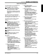
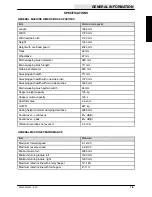
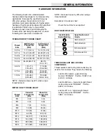
Page 4: ...GENERAL INFORMATION 1 2 6200D 330395 8 99 ...

Page 5: ...from refueling area Make sure all safety devices are in place and operate properly Check brakes and steering for proper operation 3 When starting machine Keep foot on brake and directional pedal in neutral 4 When using machine Use brakes to stop machine Go slowly on inclines and slippery surfaces Use care when reversing machine Do not carry riders on machine Always follow safety and traffic rules ...

Page 6: ...damaged or illegible install a new label in its place HOPPER SUPPORT LABEL LOCATED ON BOTH LIFT ARMS AND THE HOPPER SUPPORT BAR HOPPER LIFT ARMS LABEL LOCATED ON BOTH LIFT ARMS EMISSIONS LABEL LOCATED BEHIND THE OPERATOR S SEAT FOR SAFETY LABEL LOCATED ON THE SIDE OF THE OPERATOR COMPARTMENT MOVING BELT AND FAN LABEL LOCATED ON TOP OF THE RADIATOR SHROUD ...

Page 7: ...Sweeping path width with two side brushes 1400 mm Main sweeping brush pattern width 65 mm Hopper weight capacity 135 kg Hopper volume capacity 125 L Dust filter area 4 6 sq m GVWR 927 kg Ceiling height minimum dumping clearance 2286 mm Sound level continuous 81 dB A Sound level peak 81 dB A Vibration level does not exceed 2 5 m s GENERAL MACHINE PERFORMANCE Item Measure Maximum forward speed 8 1 k...

Page 8: ...m gov 2 5 L SAE 10W 30 2500 50 rpm gov 2500 50 rpm gov 2 5 L SAE 10W 30 CD CE rated CD CE rated STEERING Type Power source Emergency steering Front wheel manual controlled Manual steering Manual HYDRAULIC SYSTEMS System Capacity Fluid Type Main hydraulic reservoir 7 58 L TENNANT part no 65869 above 7 C Main hydraulic total 9 48 L TENNANT part no 65870 below 7 C Hydraulic lift reservoir 0 53 L TENN...

Page 9: ...GENERAL INFORMATION 1 7 6200D 330395 6 02 TOP VIEW SIDE VIEW 1783 mm 1067 mm 2035 mm FRONT VIEW 1435 mm 1397 mm 352945 MACHINE DIMENSIONS ...

Page 10: ...de skirts Check for damage wear and adjustment 2 9 Main brush Check for damage wear and adjustment 1 6 Side brush es Check for damage wear and adjustment 1 2 Check brush pattern 1 2 13 Hopper dust filter Shake 1 50 Hours 9 Main brush Rotate end for end 1 Check brush pattern 1 1 Fuel lines Check for damage and wear All 100 Hours 1 Engine Change oil and filter element EO 1 g Replace air filter eleme...

Page 11: ... es guard Check for damage or wear 1 2 16 Radiator hoses and clamps Check tension and wear 2 400 Hours 1 Fuel filter cartridge Replace element 1 800 Hours 14 Hydraulic fluid reservoirs Change hydraulic fluid HYDO 2 14 Hydraulic hoses Check for wear and damage All 14 Hydraulic fluid filter Replace filter element 1 14 Main hydraulic reservoir cap Replace cap 1 14 Main hydraulic reservoir strainer Re...

Page 12: ...he machine at the loading edge of the truck or trailer FOR SAFETY Use truck or trailer that will support the weight of the machine NOTE Empty the hopper before transporting the machine 2 If the loading surface is not horizontal or is higher than 380 mm 15 in from the ground use a winch to load machine If the loading surface is horizontal AND is 380 mm 15 in or less from the ground the machine may ...

Page 13: ... the holes in the front of the machine frame The rear tie down locations are the holes in the sides of the machine frame near the rear bumper 6 If the loading surface is not horizontal or is higher than 380 mm 15 in from the ground use a winch to unload machine If the loading surface is horizontal AND is 380 mm 15 in or less from the ground the machine may be driven off the truck or trailer FOR SA...

Page 14: ...level surface set parking brake turn off machine and remove key The front jacking locations are on the flat bottom edge of the front of the machine frame The rear jacking locations are on the corners of the rear frame FOR SAFETY When servicing machine block machine tires before jacking up machine FOR SAFETY When servicing machine jack up machine at designated locations only Block machine up with j...

Page 15: ... 291 380 313 407 424 552 1 00 in 500 650 678 881 757 984 1026 1334 NOTE Decrease torque by 20 when using a thread lubricant METRIC BOLT TORQUE CHART Thread Size Class 8 8 Torque ft lb _Nm Class 10 9 Torque ft lb Nm M4 2 3 3 4 M5 4 5 6 8 M6 7 9 10 14 M8 18 24 25 34 M10 32 43 47 64 M12 58 79 83 112 M14 94 127 133 180 M16 144 195 196 265 M20 260 352 336 455 M24 470 637 664 900 NOTE Decrease torque by...

Page 16: ... ft lb 12 Nm 0 38 0 56 18 20 ft lb 27 Nm 0 50 0 75 16 30 ft lb 41 Nm 0 62 0 88 14 40 ft lb 54 Nm 0 75 1 12 12 70 ft lb 95 Nm 1 0 1 31 12 90 ft lb 122 Nm HYDRAULIC O RING FITTING TORQUE CHART Tube O D in Thread Size Minimum Torque Maximum Torque 0 25 0 44 20 6 ft lb 8 Nm 9 ft lb 12 Nm 0 38 0 56 18 13 ft lb 18 Nm 20 ft lb 27 Nm 10 ft lb 14 Nm 12 ft lb 16 Nm 0 50 0 75 16 20 ft lb 27 Nm 30 ft lb 41 Nm...

Page 17: ...brushes Main and side brushes not adjusted properly Adjust main and side brushes Debris caught in main brush drive mechanism Remove debris from drive mechanism Main brush drive failure Contact Tennant service personnel Side brush drive failure Contact Tennant service personnel Hopper full Empty hopper Hopper lip skirts worn or damaged Replace lip skirts Wrong sweeping brush Contact Tennant represe...

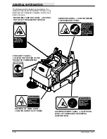
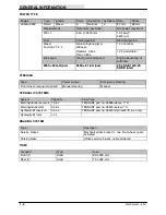
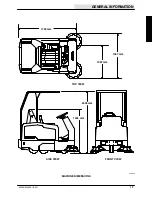
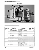
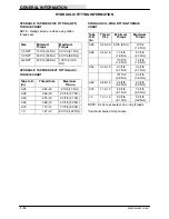
Page 18: ...GENERAL INFORMATION 1 16 6200D 330395 8 99 ...

Page 19: ...TER BEARING ASSEMBLY 2 17 TO REMOVE FRONT DRIVE ASSEMBLY 2 18 TO INSTALL FRONT DRIVE ASSEMBLY 2 20 TO REPLACE DRIVE ASSEMBLY CASTER BEARING AND THRUST WASHERS 2 22 TO REPLACE DRIVE ASSEMBLY PIVOT CONE BEARING 2 27 TO REPLACE FRONT TIRE AND WHEEL ASSEMBLY 2 30 TO REPLACE FRONT DRIVE ASSEMBLY OUTER WHEEL BEARING 2 34 TO REPLACE FRONT DRIVE ASSEMBLY INNER WHEEL BEARING 2 36 Page STEERING 2 40 TO ADJU...

Page 20: ...CHASSIS 2 2 6200D 330395 8 99 ...

Page 21: ...CHASSIS 2 3 6200D 330395 8 99 INTRODUCTION This section includes information on the main chassis related components for example the seat steering brakes and tires ...

Page 22: ... slide the seat backward or forward to the desired position and release the lever DELUXE SUSPENSION SEAT OPTION The deluxe suspension seat has four adjustments The adjustments are for the lumbar support backrest angle operator weight adjustment and front to back adjustment The lumbar adjustment knob controls the firmness of the lumbar support Increase firmness Turn knob clockwise Decrease firmness...

Page 23: ...rols the firmness of the operator s seat Increase firmness Turn the weight adjustment knob clockwise Decrease firmness Turn the weight adjustment knob counterclockwise Use the gauge next to the weight adjustment knob to help determine proper seat firmness for the operator The front to back adjustment lever adjusts the seat position Adjust Pull the lever out and slide the seat forward or backward t...

Page 24: ...is touching the floor at all times BRAKES AND TIRES SERVICE BRAKES The service brake is located on the front wheel assembly It is actuated with a foot brake pedal in the operators compartment PARKING BRAKE The parking brake is located on the front wheel assembly It is actuated with a smaller toe lever on the top of the foot brake pedal in the operators compartment It is deactivated by simply pushi...

Page 25: ... corner 2 Locate the area where the brake cable attaches to the drive support The beginning adjustment should be 1 375 in of conduit showing on the cable end 3 Turn the steering wheel all the way to the right 4 Loosen the two jam nuts on the brake cable where it attaches to the drive support casting 5 Move the cable away from the brake lever far enough to remove the slack in the pedal movement 6 R...

Page 26: ...corner 2 Locate the area where the brake cable attaches to the drive support The beginning adjustment should be 1 375 in of conduit showing on the cable end 3 Turn the steering wheel all the way to the right 4 Loosen the two jam nuts on the brake cable where it attaches to the drive support casting 5 Move the cable away from the brake lever far enough to remove the slack in the pedal movement 6 Re...

Page 27: ...e Block Rear Wheels 1 Raise the seat support and disconnect the battery cables 2 Raise the front of the machine and place jack stands under the frame 3 Mark disconnect and plug the hydraulic hoses leading to the drive motor NOTE Observe hydraulic cleanliness requirements when opening hydraulic lines 4 Remove the four hex screws holding the outer plate motor and drive hub to the main drive assembly...

Page 28: ...ve assembly This will expose the brake shoes 10 Remove the large C spring holding the two brake shoes together Remove the brake shoes NOTE There is a great deal of tension on the C spring Care must be used when spreading the spring for removal or installation 11 Install the new brake shoes on the drive assembly in the same orientation as the old ones were removed 12 Reinstall the C spring on the n...

Page 29: ...off the hex sleeve to 0 ft lbs Re torque hex sleeve to 30 ft lbs 15 Install the lock bolt in the end of the hex sleeve Tighten the lock bolt to 200 Nm 150 ft lb while holding the hex sleeve from turning 16 Reinstall the hub cap in the drive assembly 17 Go to the other side of the drive assembly and install the plate hub and motor assembly onto the drive assembly ...

Page 30: ...to 18 24 Nm 15 20 ft lb 19 Reconnect the hydraulic hoses to the drive motor 20 Remove the jack stands and lower the machine 21 Reconnect the battery cables 22 Drive the machine and check the brakes for proper operation Adjust if necessary See TO ADJUST SERVICE BRAKES instructions ...

Page 31: ...e Set Parking Brake 1 Jack up the rear corner of the machine where the tire needs to be removed NOTE Do not raise both rear wheels off the floor at the same time The machine will become unstable because of the single front tire 2 Go under the machine in the area of the rear tire Locate the lock nut holding the axle shaft to the machine frame Remove the lock nut and washer 3 Support the tire while ...

Page 32: ... the hole in the wheel bearing with the axle hole in the frame NOTE The lug nuts must face the outside of the machine 2 Install the axle shaft in the machine from the outside of the frame NOTE The axle has a flat portion that must line up with the flat in the axle mount hole 3 Install the washer and nut on the axle Tighten to 68 81 Nm 50 60 ft lb 4 Remove the jack stands and lower the machine 5 Dr...

Page 33: ...ke 1 Remove the rear wheel assembly See TO REMOVE REAR TIRE instructions 2 Remove the three lug nuts holding the bearing housing to the wheel assembly Remove the bearing housing 3 Use a press to remove the wheel bearings from the housing 4 Press the new wheel bearings into the housing Press the bearing in until the flange is seated on the housing ...

Page 34: ...l on the bearing housing coining on wheel facing lug nuts Tighten the three lug nuts to 58 76 Nm 43 56 ft lb NOTE The lug nuts must face the outside of the machine 6 Reinstall the rear wheel assembly in the machine See TO INSTALL REAR TIRE instructions ...

Page 35: ...nd steering The brakes are actuated with a cable and uses a sprocket and chain assembly for the steering Forward and reverse is accomplished with an hydraulic motor and drive hub FRONT WHEEL SUPPORT CASTER BEARING ASSEMBLY The front wheel support caster bearing is located between the bottom swivel plate and the upper swivel plate weldment The bearing is a flat needle bearing style ...

Page 36: ... 2 Raise the front of the machine and place jack stands under the frame 3 Mark plug and disconnect the hydraulic hoses leading to the drive motor NOTE Observe hydraulic cleanliness requirements when opening hydraulic lines 4 Go in operators compartment and loosen the lower steering shaft mount screws 5 Pull the mount back to give the steering chain slack Locate and remove the master link and steer...

Page 37: ... the wheel support Remove the brake cable from the wheel support 8 Position a floor jack or transmission jack under the drive wheel This will support the drive assembly when the hardware is removed 9 Go to the operators compartment and locate the 4 button head screws holding the drive assembly to the floor plate Remove the 4 screws while supporting the drive assembly 10 Remove the drive assembly f...

Page 38: ...upport the drive assembly when installing it in the machine 4 Position the drive assembly under the machine in front 5 Raise the drive assembly up until the mount holes in the floor plate are aligned with the mount holes in the upper swivel plate weldment on top of the drive assembly NOTE Make sure to position the grease zerk in the access hole in the machine floor plate 6 Install the four button ...

Page 39: ...n and clevis pin in the end of the brake cable where it attaches to the lever on the wheel support 10 Reconnect the hydraulic hoses to the drive motor 11 Remove the jack stands and lower the machine 12 Reconnect the battery cables 13 Operate the machine and check for proper operation Check the brakes for proper operation Adjust if necessary See TO ADJUST SERVICE BRAKES instructions ...

Page 40: ... On Level Surface Set Parking Brake 1 Remove the drive assembly from the machine See TO REMOVE FRONT DRIVE ASSEMBLY instructions 2 Remove the four hex screws holding the outer plate drive motor and drive hub to the main drive assembly 3 Pull the drive hub outer plate and hydraulic motor out of the drive wheel and away from the drive assembly ...

Page 41: ... assembly to the drive assembly 5 Remove the sprocket from the pivot assembly 6 Remove the cotter pin and castle nut from the upper swivel plate weldment 7 Remove the flat washer and cone bearing from the bottom swivel plate 8 Lift the bottom swivel plate off the upper swivel plate weldment ...

Page 42: ...tion the new caster bearing on top of the new lower thrust washer 12 Reinstall the second new thrust washer on top of the new caster bearing 13 Reinstall the bottom swivel plate on the upper swivel plate weldment Make sure the grease seal is in place on the upper swivel plate weldment 14 Reinstall the bearing cone and flat washer on the bottom swivel plate Make sure the bearing cone is greased ...

Page 43: ...e turned by hand Reduce torque if necessary 16 Reinstall the sprocket on the front drive assembly 17 Reinstall the pivot and sprocket assembly on the drive assembly Reinstall the four screws and tighten to 68 81 Nm 50 60 ft lb 18 Install the drive hub outer plate and drive motor assembly onto the pins of the drive assembly 19 Install the 4 hex screws and washers Tighten to 18 24 Nm 15 20 ft lb ...

Page 44: ...the drive assembly in the machine See TO INSTALL FRONT DRIVE ASSEMBLY instructions 21 Operate the machine and check for smooth steering operation Check the brakes for proper operation Adjust if necessary See TO ADJUST SERVICE BRAKES instructions ...

Page 45: ...ace Set Parking Brake 1 Remove the drive assembly from the machine See TO REMOVE FRONT DRIVE ASSEMBLY instructions 2 Remove the four hex screws holding the outer plate drive motor and drive hub assembly to the main drive assembly 3 Pull the drive hub outer plate and drive motor assembly out of the drive wheel and away from the drive assembly ...

Page 46: ...nut from the upper swivel plate weldment 7 Remove the flat washer and old cone bearing from the bottom swivel plate 8 Install the new cone bearing and flat washer on the bottom swivel plate Make sure the new cone bearing is greased 9 Reinstall the castle nut and tighten to 200 Nm 150 ft lbs Then tighten to the next nearest hole and install the cotter pin 10 Reinstall the sprocket on the pivot asse...

Page 47: ...motor assembly into the wheel assembly and onto the pins of the drive assembly 13 Install the 4 hex screws and washers Tighten to 18 24 Nm 15 20 ft lb 14 Reinstall the drive assembly in the machine See TO INSTALL FRONT DRIVE ASSEMBLY instructions 15 Operate the machine and check for smooth steering operation Check the brakes for proper operation Adjust if necessary See TO ADJUST SERVICE BRAKES ins...

Page 48: ... front of the machine and place jack stands under the frame 3 Mark disconnect and plug the hydraulic hoses leading to the drive motor NOTE Observe hydraulic cleanliness requirements when opening hydraulic lines 4 Remove the four hex screws holding the outer plate drive motor and drive hub assembly to the main drive assembly 5 Pull the drive hub outer plate and drive motor out of the drive wheel an...

Page 49: ...the lock bolt this is a right hand thread screw 8 Remove the hex sleeve and outer bearing cone assembly this is a left hand thread nut 9 The inner bearing axle shaft and tire wheel assembly can now be removed from the drive assembly Use a press to remove the inner bearing from the existing tire wheel assembly 10 Install the inner bearing on the new tire wheel assembly ...

Page 50: ... 12 Reinstall the outer bearing and hex sleeve assembly this is a left hand thread nut Tighten to at least 100 ft lbs and then back off the hex sleeve to 0 ft lbs Re torque hex sleeve to 30 ft lbs 13 Install the lock bolt in the end of the hex sleeve Tighten the lock bolt to 200 Nm 150 ft lb while holding the hex sleeve from turning 14 Reinstall the hub cap in the drive assembly ...

Page 51: ...assembly into the wheel assembly and onto the pins of the drive assembly 16 Install the 4 hex screws and washers Tighten to 18 24 Nm 15 20 ft lb 17 Reconnect the hydraulic hoses to the drive motor 18 Reconnect the battery cables 19 Remove the jack stands and lower the machine 20 Drive the machine and check for proper operation ...

Page 52: ...the frame 3 Go to the side of the drive assembly opposite the drive motor and remove the hub cap This will expose the outer bearing hex sleeve and lock bolt 4 Remove the lock bolt this is a right hand thread screw 5 Remove the hex sleeve and outer bearing cone assembly this is a left hand thread nut 6 Use a press to remove the old outer bearing cone from the hex sleeve Install a new outer bearing ...

Page 53: ...eve to 0 ft lbs Re torque hex sleeve to 30 ft lbs 8 Install the lock bolt this is a right hand thread screw in the end of the hex sleeve Tighten the lock bolt to 200 Nm 150 ft lb while holding the hex sleeve from turning 9 Reinstall the hub cap in the drive assembly 10 Reconnect the battery cables 11 Remove the jack stands and lower the machine 12 Drive the machine and check for proper operation ...

Page 54: ...e front of the machine and place jack stands under the frame 3 Mark disconnect and plug the hydraulic hoses leading to the drive motor NOTE Observe hydraulic cleanliness requirements when opening hydraulic lines 4 Remove the four hex screws holding the outer plate drive motor and drive hub assembly to the main drive assembly 5 Pull the drive hub outer plate and drive motor assembly out of the driv...

Page 55: ...t hand thread screw 8 Remove the hex sleeve and outer bearing cone assembly this is a left hand thread nut 9 The inner bearing axle shaft and tire wheel assembly can now be removed from the drive assembly Use a press to remove the inner bearing from the existing tire wheel assembly Discard the old wheel bearing 10 Press a new inner wheel bearing on the wheel shaft Apply grease to the new bearing ...

Page 56: ...2 Reinstall the outer bearing and hex sleeve assembly this is a left hand thread nut Tighten to at least 100 ft lbs and then back off the hex sleeve to 0 ft lbs Re torque hex sleeve to 30 ft lbs 13 Install the lock bolt in the end of the hex sleeve Tighten the lock bolt to 200 Nm 150 ft lb while holding the hex sleeve from turning 14 Reinstall the hub cap in the drive assembly ...

Page 57: ...assembly into the wheel assembly and onto the pins of the drive assembly 16 Install the 4 hex screws and washers Tighten to 18 24 Nm 15 20 ft lb 17 Reconnect the hydraulic hoses to the drive motor 18 Reconnect the battery cables 19 Remove the jack stands and lower the machine 20 Drive the machine and check for proper operation ...

Page 58: ...ed by following the adjustment procedure listed below TO ADJUST STEERING CHAIN FOR SAFETY Before Leaving Or Servicing Machine Stop On Level Surface Set Parking Brake 1 Go into the operators compartment and locate the two hex screws holding the lower steering shaft bearing assembly to the floor plate Loosen these two hex screws 2 Push the lower steering shaft assembly forward until the slack has be...

Page 59: ...o under the machine and locate the steering chain 4 Rotate the steering wheel until the master link on the chain is accessible 5 Remove the chain master link Remove the steering chain from both sprockets 6 Remove and discard the steering chain from the machine 7 Route the new chain around both steering sprockets Install the master link 8 Remove the jack stands and lower the machine Reconnect the b...

Page 60: ...rive assembly from the machine See TO REMOVE FRONT DRIVE ASSEMBLY instructions 2 Remove the four hex screws holding the pivot and sprocket assembly to the drive assembly 3 Remove the old sprocket from the pivot assembly 4 Install the new sprocket on the pivot assembly NOTE Make sure the roll pin in the top of the drive assembly lines up with the hole in the sprocket ...

Page 61: ...ly on the drive assembly Reinstall the four screws and tighten to 68 81 Nm 50 60 ft lb 6 Reinstall the drive assembly in the machine See TO INSTALL FRONT DRIVE ASSEMBLY instructions 7 Reconnect the battery cables 8 Operate the machine and check for smooth steering operation ...

Page 62: ...nt of the machine and place jack stands under the frame 3 Go into the operators compartment and locate the lower steering shaft mount assembly Loosen the two screws and pull the mount back to give the steering chain slack 4 Go under the machine and locate the steering chain 5 Rotate the steering wheel until the master link on the chain is accessible 6 Remove the chain master link Remove the steeri...

Page 63: ... the new small sprocket on the lower steering shaft Firmly tighten the set screws 9 Route the steering chain around both steering sprockets Install the master link 10 Adjust the steering chain See TO ADJUST STEERING CHAIN instructions 11 Remove the jack stands and lower the machine 12 Operate the machine and check the steering for proper operation ...

Page 64: ...s under the machine frame 2 Turn the steering wheel all the way to the left 3 Go to the operators compartment and locate the steering U joint Loosen the two set screws on the top of the steering U joint 4 Pull the steering wheel and long steering shaft up and out of the top of the steering U joint 5 Remove the two hex screws holding the steering bearing housing to the machine frame Push the bearin...

Page 65: ...7 Locate the master link on the steering chain Remove the master link and steering chain from the small steering sprocket 8 Remove the steering housing from the machine 9 Loosen the two set screws holding the U joint to the top of the short steering shaft Remove and retain the U joint and square key ...

Page 66: ...iscard the bearings Retain the short shaft Note the orientation of the shaft in the housing 12 Use the arbor press to install the new bearings into the steering housing 13 Use the arbor press to install the short steering shaft into the new bearings 14 Reinstall the small steering sprocket and woodruff key on the bottom of the steering housing Tighten the set screws tight 15 Reinstall the U joint ...

Page 67: ...g chain around the small steering sprocket Reinstall the master link 19 Turn the steering wheel all the way to the left and then to the right Find the point in the rotation where the steering chain is the tightest 20 Push the bearing housing forward in the slots This will remove any excess slack in the steering chain Tighten the two hex screws to 37 48 Nm 26 34 ft lb 21 Remove the jack stands and ...

Page 68: ... Install jack stands under the machine frame 2 Go to the operators compartment and locate the steering U joint Loosen the two set screws on the top of the steering U joint 3 Pull the steering wheel and long steering shaft up and out of the top of the steering U joint 4 Loosen the two set screws holding the U joint to the top of the short steering shaft Remove and discard the U joint and square key...

Page 69: ...are key on the top of the steering housing Tighten the set screws tight 6 Position the long steering shaft and steering wheel into the top of the steering U joint Tighten the set screws tight 7 Operate the machine and check the steering U joint for proper operation ...

Page 70: ...ed of the machine with the pressure of your foot on the pedal the harder you press the faster the machine travels Use the brake pedal to stop the machine TO REMOVE DIRECTIONAL PEDAL ASSEMBLY FOR SAFETY Before Leaving Or Servicing Machine Stop On Level Surface Set Parking Brake 1 Open the seat support and engage the prop rod 2 Disconnect the machine batteries ...

Page 71: ... the directional pedal linkage rod and control valve 5 Disconnect the directional pedal link at the lower ball joint 6 Go the the operators compartment and locate the directional pedal assembly Remove the four thread rolling screws holding the directional pedal to the floor plate 7 Remove the pedal assembly from the machine ...

Page 72: ... Parking Brake 1 Position the directional pedal assembly in the machines operators compartment 2 Position the pedal link through the access hole in the floor plate 3 Line up the mount holes in the pedal assembly plate with the mount holes in the machines floor plate 4 Reinstall the four thread rolling screws and tighten to 8 10 Nm 6 7 ft lb ...

Page 73: ... of the right hand side brush Locate the control valve pivot link Position the ball joint into the hole on the pivot Tighten the nut 6 Reconnect the battery cables 7 Disengage the prop rod and lower the seat support 8 Start the machine and check for proper operation ...

Page 74: ...CHASSIS 2 56 6200D 330395 8 99 ...

Page 75: ... 3 25 TO REPLACE MAIN BRUSH JACKSHAFT BELT 3 25 TO REPLACE MAIN BRUSH JACKSHAFT INNER BEARING 3 28 TO REPLACE MAIN BRUSH JACKSHAFT OUTER BEARING 3 33 SIDE BRUSH 3 41 REPLACING SIDE BRUSH 3 41 SIDE BRUSH GUARD 3 43 SIDE BRUSH PIVOT 3 43 TO REPLACE SIDE BRUSH LIFT CABLE 3 44 SKIRTS AND SEALS 3 47 REAR SKIRT 3 47 SIDE SKIRTS 3 47 LARGE DEBRIS TRAP SKIRT 3 48 FRONT SKIRT 3 48 HOPPER SEALS 3 49 HOPPER ...

Page 76: ...SWEEPING 3 2 6200D 330395 8 99 ...

Page 77: ... section includes information on the sweeping operation of the model 6200D The side brush sweeps debris in front of the machine and the main brush sweeps the debris into the hopper The vacuum fan pulls air from the hopper and through the dust filter ...

Page 78: ...behind the battery compartment The hopper is raised and lowered with an hydraulic lift cylinder The lift cylinder is provided hydraulic flow from a electro hydraulic unit The electro hydraulic unit is activated with a dash mounted switch The hopper is held in the raised position with a prop arm ...

Page 79: ...switch to the Filter shaker position D TAPPING Remove the filter and tap the filter gently on a flat surface with the dirty side down Do not damage the edges of the filter element and seals or the filter will not seat properly in the filter frame D AIR Blow air through the dust filter opposite the direction of the arrows This may be done with the dust filter in the machine Always wear eye protecti...

Page 80: ...fore leaving or servicing machine stop on level surface set parking brake turn off machine and remove key 2 Unlatch and remove hopper cover 3 Unplug the filter shaker from the main harness NOTE Carefully pull the wires apart from the bodies of the plugs Do not unplug the connections from the shaking mechanism Do not pull on the wires Damage could occur to the wires or the shaking mechanism 4 Lift ...

Page 81: ...g releasing tension from the shaking mechanism 6 Lift the VCSt system filter shaker off of the filter 7 Clean or discard the Instant Accesst filter as required 8 Replace the VCSt system filter shaker Use care to insert the shaking pin into the filter comb correctly ...

Page 82: ...loose it will not function properly 10 The filter shaker should lay flat against the filter Check to make sure the comb tab is not caught below the filter shaker plate 11 Check the shaker solenoid gap with the end of the shipping tab The gap should be the same width as the tab If it is not loosen the mounting screws adjust the gap by repositioning the shaker solenoid then retighten the screws 12 R...

Page 83: ...SWEEPING 3 9 6200D 330395 6 02 13 Reconnect the main harness to the shaker mechanism 14 Check the dust filter seals 15 Replace hopper cover and secure with latches ...

Page 84: ... with the main brush in the lowered position Rotate the main brush end for end after every 50 hours of operation for maximum brush life and best sweeping performance Replace the main brush when the remaining bristles measure 25 mm 1 in in length TO REPLACE MAIN BRUSH FOR SAFETY Before Leaving Or Servicing Machine Stop On Level Surface Set Parking Brake 1 Stop the machine set the parking brake and ...

Page 85: ...or next to the access door 6 Slide the main brush onto the drive plug Rotate the brush until it engages the drive plug and push it all the way onto the plug 7 Check that the recirculation skirt is tucked in behind the frame 8 Slide the main brush idler arm plug onto the main brush 9 Secure the idler arm on the bolts Hand tighten the mounting knobs 10 Close the main brush access door ...

Page 86: ...k will remain on the floor 4 Raise the main brush 5 Drive the machine off the test area 6 Observe the width of the brush pattern The proper brush pattern width is 50 to 75 mm 2 3 in The brush taper is factory set and should not need adjustment unless parts of the brush system have been replaced If the main brush pattern is tapered more than 15 mm 0 5 in on one end than the other adjust the taper a...

Page 87: ...g Machine Stop On Level Surface Set Parking Brake 1 Remove the four screws holding the right hand brush door to the machine frame Remove the right hand side brush door 2 Remove the vacuum fan drive belt from the lower sheave See TO REPLACE VACUUM FAN DRIVE BELT instructions in this section 3 Locate the main brush drive belt idler pulley between the small drive pulley and the larger brush pulley 4 ...

Page 88: ...onto the brush drive pulleys 8 Move the idler pulley forward in the slot until the belt is tight Tighten the hex nut to 18 24 Nm 15 20 ft lb 9 Reinstall the vacuum fan drive belt onto the lower sheave See TO REPLACE VACUUM FAN DRIVE BELT instructions in this section 10 Reinstall the right hand side brush door 11 Operate the machine and check the main brush for proper operation ...

Page 89: ...e Stop On Level Surface Set Parking Brake 1 Open the left hand side brush door 2 Remove the main brush idler mount plate See TO REPLACE MAIN BRUSH instructions in this sections 3 Remove the idler arm from the brush lift plate 4 Remove the hex screw nut and washer holding the idler plug assembly to the brush lift plate ...

Page 90: ...x screws holding the bearing retainer to the idler plug Remove the retainer 7 Remove and discard the idler ball bearing from the idler plug 8 Position the new ball bearing into the idler plug 9 Reinstall the bearing retainer plate on the idler plug Reinstall the four screws and tighten to 8 10 Nm 6 7 ft lb ...

Page 91: ...ew washer and nyloc nut Tighten to 37 48 Nm 26 34 ft lb 11 Reinstall the idler arm onto the brush lift plate 12 Reinstall the main brush idler mount plate See TO REPLACE MAIN BRUSH instructions in this sections 13 Close the left hand side brush door 14 Operate the machine and check the main brush for proper operation ...

Page 92: ...he jack points Install jack stands under the machine frame 2 Open the left hand side brush door Remove the right hand brush door 3 Remove the main brush idler mount plate See TO REPLACE MAIN BRUSH instructions in this sections 4 Remove the main brush See TO REPLACE MAIN BRUSH instructions in this sections 5 Remove the main brush drive belt See TO REPLACE MAIN BRUSH DRIVE BELT instructions in this ...

Page 93: ...A LEFT HAND THREAD NUT 7 Remove the main brush V belt pulley larger one from the main brush shaft Make sure to retain the washer from behind the pulley 8 Hold the main brush drive plug from turning Remove the large nut from the center of the drive plug NOTE THIS IS A LEFT HAND THREAD NUT 9 Remove the main brush idler plug assembly from the main brush shaft ...

Page 94: ...ew driver or punch to remove the remaining outer bearing from the main brush housing Discard the bearing 14 Use an arbor press to remove the bearing from the main brush shaft Discard the bearing 15 Install one new bearing onto the main brush shaft 16 Install one new bearing into the outer side of the main brush bearing housing 17 Install the new bearing and main brush shaft assembly into the main ...

Page 95: ... Hand tighten tight 19 Reinstall the washer and V belt pulley onto the outside of the main brush shaft Reinstall the left hand nut Tighten to 52 67 Nm 39 51 ft lb 20 Reinstall the main brush drive belt See TO REPLACE MAIN BRUSH DRIVE BELT instructions in this section 21 Reinstall the main brush See TO REPLACE MAIN BRUSH instructions in this sections ...

Page 96: ... 22 6200D 330395 8 99 22 Reinstall the right hand brush door and close the left hand brush door 23 Remove the jack stands and lower the machine 24 Operate the machine and check the main brush for proper operation ...

Page 97: ...he four screws holding the right hand brush door to the machine frame Remove the right hand side brush door 2 Locate the main brush drive belt idler pulley between the small drive pulley and the larger brush pulley 3 Loosen the hex nut in the center of the idler pulley 4 Push the idler pulley back in the slot 5 Remove the main brush drive belt from the two remaining pulleys ...

Page 98: ... the hex bolt Reinstall the hex nut Leave loose for now 8 Reinstall the V belt around the two drive pulleys and on top of the idler pulley 9 Pull down on the idler pulley until the belt is tight Tighten the pulley nut to 18 24 Nm 15 20 ft lb 10 Reinstall the right hand side brush door 11 Operate the machine and check the main brush for proper operation ...

Page 99: ...g belt and fan Keep away TO REPLACE MAIN BRUSH JACKSHAFT BELT FOR SAFETY Before Leaving Or Servicing Machine Stop On Level Surface Set Parking Brake 1 Open the seat support and engage the prop rod Disconnect the battery cables 2 Remove the main brush See TO REPLACE MAIN BRUSH instructions in this section 3 Locate the main brush jack shaft belt tension idler pulley mount plate near the flywheel she...

Page 100: ...sion spring 5 Push the idler pulley mount plate down to loosen the tension on the main brush center V belt 6 Remove the V belt from the engine sheave idler sheaves and main brush jack shaft sheave Remove the V belt from the machine 7 Install the new V belt onto the engine sheave idler sheaves and main brush shaft sheave ...

Page 101: ... plate and reconnect the tension spring Tighten the jam nuts on the threaded rod until the tension spring is 4 5 in long 9 Reinstall the main brush 10 Disengage the seat rod and close the seat assembly 11 Operate the machine and check the main brush for proper operation ...

Page 102: ...eaving Or Servicing Machine Stop On Level Surface Set Parking Brake 1 Open the seat support and engage the prop rod Disconnect the battery cables 2 Remove the main brush See TO REPLACE MAIN BRUSH instructions in this section 3 Locate the main brush jack shaft belt on the engine mounted sheave plate ...

Page 103: ... spring 5 Push the idler pulley mount plate down to loosen the tension on the main brush center V belt 6 Remove the V belt from the main brush jack shaft sheave 7 Locate the main brush jack shaft V belt sheave in the brush compartment area Loosen the two set screws Remove the sheave from the jack shaft Retain the square key ...

Page 104: ...ws on the bearing lock collar 9 Remove the two hex screws and nuts holding the bearing flanges to the mount bracket 10 Remove the outer bearing flange from the mount bracket 11 Pull the inner bearing off the jack shaft Leave the inner bearing flange in place ...

Page 105: ...the hardware Leave loose for now 14 Push the bearing in until it is seated against the inner flange Tighten the hardware to 18 24 Nm 15 20 ft lb Hand tighten the two bearing collar set screws tight 15 Reinstall the sheave onto the end of the jack shaft Make sure the square key is in place on the jack shaft Position the sheave so the face is flush with the end of the shaft Hand tighten the two shea...

Page 106: ...aft sheave 17 Pull the tension idler pulley mount plate and reconnect the tension spring Tighten the jam nuts on the threaded rod until the tension spring is 4 5 in long 18 Reinstall the main brush 19 Start the machine and operate the main brush Check for proper operation ...

Page 107: ...eaving Or Servicing Machine Stop On Level Surface Set Parking Brake 1 Open the seat support and engage the prop rod Disconnect the battery cables 2 Remove the main brush See TO REPLACE MAIN BRUSH instructions in this section 3 Locate the main brush jack shaft belt on the engine mounted sheave plate ...

Page 108: ...d rod Remove the tension spring 5 Push the idler pulley mount plate down to loosen the tension on the main brush center V belt 6 Remove the V belt from the main brush jack shaft sheave 7 Remove the four screws holding the right hand brush door to the machine frame Remove the right hand side brush door ...

Page 109: ... the vacuum fan housing to the machine frame 10 Push the vacuum fan assembly forward in the slots to loosen the vacuum fan V belt 11 Remove the vacuum fan V belt from the two groove jack shaft sheave 12 Locate the main brush drive belt idler pulley between the jack shaft drive pulley and the larger brush pulley 13 Loosen the hex nut in the center of the idler pulley 14 Push the idler pulley back i...

Page 110: ...l the sheave off the shaft Retain the shaft key 16 Loosen the two set screws on each of the jack shaft bearing locking collars 17 Loosen the hardware holding each of the two jack shaft bearing flanges to the mount brackets 18 Push the jack shaft in toward the center of the machine Push the shaft in far enough so it clears the outer bearing ...

Page 111: ...bearing flange in place 21 Position the new outer bearing and the outer bearing flange onto the mount plate Reinstall the two nuts Leave hardware loose for now 22 Push the jack shaft through the new bearing until the end is showing out the right hand side of the brush wrap 23 Go under the machine in the brush wrap area Tighten the hardware holding the two jack shaft bearing flanges to the mount br...

Page 112: ...and the bearing flange mount bracket is about 1 5 inch 25 Hand tighten the two set screws on each jack shaft bearing tight 26 Position the V belt over the jack shaft sheave 27 Pull the tension idler pulley mount plate and reconnect the tension spring Tighten the jam nuts on the threaded rod until the tension spring is 4 5 in long ...

Page 113: ...sheave small sheave to the inside onto the outer end of the jack shaft Hand tighten the two set screws tight 30 Position the main brush drive belt onto the jack shaft and brush drive pulleys 31 Move the idler pulley forward in the slot until the belt is tight Tighten the hex nut to 18 24 Nm 15 20 ft lb 32 Install the vacuum fan V belt over the jack shaft sheave ...

Page 114: ...tension is when the belt deflects 8 38 mm 0 33 in from a force of 42 kg 90 to 95 lb at belt midpoint Tighten the screws hand tight 34 Tighten the five mounts screws hand tight 35 Reinstall the right hand machine cover 36 Reinstall the right hand side brush door 37 Operate the machine and check the main brush for proper operation ...

Page 115: ... Move the pulley mount bracket up or down to achieve the proper side brush pattern Retighten the hex screw The side brush should be replaced when it no longer sweeps effectively for your application A guideline length is when the remaining bristles measure 50 mm 2 in in length You may need to replace the side brush sooner if you are sweeping light litter or use a brush with shorter bristles if you...

Page 116: ...h retaining pin through the side brush hub and shaft 6 Secure the pin by clipping the pin keeper over the end of the pin 7 Adjust the side brush pattern by loosening the hex screw located above the side brush cable pulley in the front of the operators compartment Move the pulley mount bracket up or down to achieve the proper side brush pattern Retighten the hex screw ...

Page 117: ...er every 200 hours of operation Replace the brush guard after it begins to show serious wear SIDE BRUSH PIVOT The side brush pivot should be checked for excessive movement after every 200 hours of operation Torque the front and rear compression springs to reduce excessive movement ...

Page 118: ...e 2 Go under the front of the machine near the side brush Locate the side brush lift cable clevis under the brush pivot hex nut Remove the nut only Pull the side brush lift cable off the hex screw 3 Go to the operators compartment Remove the two cable pulleys sleeves and cable clips from the side brush lift cable NOTE Note the orientation of the cable clips for proper re assembly ...

Page 119: ... proper re assembly 5 Go up under the instrument panel and remove the hex screw and nut holding the end of the side brush lift cable to the lift handle Remove the side brush lift cable from the machine 6 Route the new side brush lift cable in the machine 7 Reinstall the three cable pulleys sleeves and cable clips Make sure the cable clips are in the correct orientation Tighten the hardware to 18 2...

Page 120: ...t the new side brush lift cable to the side brush pivot screw Hand tighten the hex nut Cable should pivot on the hardware 9 Connect the side brush lift cable to the lift handle 10 Raise the side brush Check the new cable for smooth operation ...

Page 121: ...0 09 in The recirculation skirt requires no adjustment Check the skirts for wear or damage and adjustment daily NOTE The recirculation skirt must be folded in between the brush and the machine frame before the brush door is mounted on for the machine to work properly SIDE SKIRTS The side skirts are located on both sides of the main brush compartment The skirts should clear the floor up to 5 mm ...

Page 122: ...he main brush curl back should be 3 4 inch 1 4 inch Sweeping performance will be adversely affected if this skirt does not contact the floor Check the skirt for wear or damage after every 100 hours of operation FRONT SKIRT The front skirt is located along the front of the main brush The front skirt can be raised with the foot pedal in the operators compartment Raising the front skirt will allow la...

Page 123: ...ion WARNING Raised hopper may fall Engage hopper support bar HOPPER DOOR SEAL The hopper door seal is located on the bottom of the hopper and seals the hopper door when the hopper door is closed Check the seal for wear or damage after every 100 hours of operation HOPPER LIP SEAL The hopper lip seal is located on the inside of the rear lip of the hopper door and seals the inside lip of the hopper d...

Page 124: ...esst filter The vacuum fan is powered by the engine and driven with a V belt VACUUM FAN BELT Check the vacuum fan belt tension and wear after every 100 hours of operation The correct tension is when the belt deflects 13 0 mm 0 50 in from a force of 15 kg 30 to 40 lb at belt midpoint WARNING Moving belt and fan Keep away ...

Page 125: ...an drive belt remove the right hand side panel Start by lifting up on the panel pop the brush lift slot over the black knob then move the panel backward and off the machine 2 Remove the right hand side brush door 3 Loosen the five hex screws holding the vacuum fan housing to the machine frame 4 Push the vacuum fan assembly forward in the slots to loosen the vacuum fan V belt ...

Page 126: ...um fan V belt from the jack shaft and impeller pulleys Remove the old V belt from the machine 7 Install the new vacuum fan V belt over both pulleys 8 Pull the vacuum fan assembly toward the back of the machine to tighten the V belt Tighten the five mounts screws hand tight 9 Reinstall the V belt cover Tighten the two screws hand tight ...

Page 127: ...SWEEPING 3 53 6200D 330395 8 99 10 Reinstall the right hand machine cover 11 Reinstall the right hand brush door 12 Operate the machine Check the vacuum fan for proper operation ...

Page 128: ... knob then move the panel backward and off the machine 2 Loosen the four hex screws holding the vacuum fan housing to the machine frame 3 Pull the vacuum fan assembly toward the back of the machine to tighten the V belt The correct tension is when the belt deflects 8 38 mm 0 41 in from a force of 42 kg 88 to 93 lb at belt midpoint 4 Tighten the four vacuum housing mount screws hand tight 5 Reinsta...

Page 129: ...move the right hand side panel Start by lifting up on the panel pop the brush lift slot over the black knob then move the panel backward and off the machine 3 Loosen the five hex screws holding the vacuum fan housing to the machine frame 4 Push the vacuum fan assembly forward in the slots to loosen the vacuum fan V belt 5 Remove the two hex screws holding the cover over the V belt pulley Remove th...

Page 130: ...ly to the machine Remove the assembly from the machine NOTE Make sure to retain the two steel sleeves from the bottom two hex screws 10 Place the assembly on a work bench with the vacuum fan inlet plate facing up 11 Remove the five hex screws and nuts holding the vacuum fan inlet plate to the bearing housing plate Remove the inlet plate from the housing NOTE Make sure to retain the five steel slee...

Page 131: ...l the nyloc nut onto the fan shaft Tighten to 11 14 Nm 7 10 ft lb 15 Reinstall the vacuum fan inlet plate onto the bearing housing plate Reinstall the five steel sleeves hex screws and nuts Center the hole in the plate over the impeller fins Tighten the hardware to 18 24 Nm 15 20 ft lb 16 Position the vacuum fan assembly onto the right side off the machine Reinstall the five hex screws and nuts Ma...

Page 132: ... toward the back of the machine to tighten the V belt The correct tension is when the belt deflects 8 38 mm 0 41 in from a force of 42 kg 88 to 93 lb at belt midpoint 19 Tighten the five mounts screws hand tight 20 Reinstall the V belt cover Tighten the two screws hand tight 21 Connect the wires to the Thermo Sentryt ...

Page 133: ...ect the wires leading to the vacuum fan shut off solenoid 23 Reinstall the right hand machine cover 24 Start the machine raise the hopper disengage the prop arm Lower the hopper 25 Operate the machine Check the vacuum fan for proper operation ...

Page 134: ...FAN IMPELLER instructions to remove the vacuum fan assembly from the machine and and the impeller from the housing NOTE Once the vacuum fan impeller has been removed go to step 2 2 Loosen the two set screws holding the V belt pulley to the fan shaft Remove the pulley 3 Remove the four hex screws holding the vacuum fan bearing assembly to the bearing plate Remove the bearing assembly ...

Page 135: ...e wide flange NOTE Make sure the bearings are pressed down tight The fan will be noisy if there is any play in the bearings The retaining rings must be tight to the housing 6 Reinstall the bearing housing onto the bearing housing plate The long end of the shaft is on the side with the sound foam Reinstall the four hex screws and washers Tighten to 8 10 Nm 6 8 ft lb 7 Reinstall the V belt pulley on...

Page 136: ...einstall the vacuum fan impeller onto the fan shaft Make sure to reinstall the square key on the fan shaft 9 See TO REPLACE VACUUM FAN IMPELLER instructions to install the vacuum fan impeller and the vacuum fan assembly into the machine ...

Page 137: ...s Main and side brushes not adjusted properly Adjust main and side brushes Debris caught in main brush drive mechanism Remove debris from drive mechanism Main brush drive failure Contact Tennant service personnel Side brush drive failure Contact Tennant service personnel Hopper full Empty hopper Hopper lip skirts worn or damaged Replace lip skirts Wrong sweeping brush Contact Tennant representativ...

Page 138: ...SWEEPING 3 64 6200D 330395 6 02 ...

Page 139: ...IRCUIT BREAKERS 4 13 TO REPLACE CIRCUIT BREAKER 4 14 SOLENOID CONTROL MODULE 4 17 THROTTLE SOLENOID 4 17 GLOW PLUG TIMER 4 17 TO REPLACE ENGINE FUEL SHUTOFF SOLENOID 4 18 TO REPLACE DUMP DOOR ACTUATOR 4 21 THERMO SENTRYt 4 24 TO REPLACE THERMO SENTRYt4 25 TO REPLACE VACUUM FAN SHUT OFF SOLENOID 4 27 TO REPLACE ENGINE STARTER 4 30 TO REPLACE MACHINE ALTERNATOR 4 33 ELECTRICAL SCHEMATIC 4 38 WIRE HA...

Page 140: ...ELECTRICAL 4 2 6200D 330395 8 99 ...

Page 141: ...ELECTRICAL 4 3 6200D 330395 8 99 INTRODUCTION The model 6200D electrical system consists of the battery instrument panel side brush motor switches relays and circuit breakers ...

Page 142: ... and switches BATTERY The battery is located under the operator s seat and can be accessed by lifting the seat up After the first 50 hours of operation and every 200 hours after that clean and tighten the battery connections Check the electrolyte level every 200 hours of operation Only add distilled water FOR SAFETY When Servicing Machine Avoid Contact With Battery Acid ...

Page 143: ...1 Open the seat support and engage the prop rod 2 Remove the battery negative cable 3 Connect the battery charger to the battery Make sure to hook the red clamp on the positive post and the black clamp to the negative post 4 Start the charger Check the voltage meter on the charger for proper charge voltage 5 Remove the charger after the voltage meter reads a full charge ...

Page 144: ...ELECTRICAL 4 6 6200D 330395 8 99 6 Reinstall the negative battery cable and start the machine Check the battery for proper operation 7 Disengage the prop rod and lower the seat support ...

Page 145: ...hine Stop On Level Surface Set Parking Brake turn off machine and remove key 1 Open the seat support and engage the prop rod 2 Locate the battery at the right hand side of the machine in front of the hydraulic tank 3 Remove the battery negative cable and positive cable from the battery terminals ...

Page 146: ...bracket to the seat support Lift the battery out of the machine 5 Install the new battery in the machine in the same orientation as the old one 6 Reconnect the battery cables to the battery red cable to positive post black cable to negative post 7 Reinstall the battery hold down bracket ...

Page 147: ...ECTRICAL 4 9 6200D 330395 8 99 8 Disengage the prop rod and lower the seat support 9 Check the new battery for proper operation If battery needs charging see TO CHARGE BATTERY instructions in this section ...

Page 148: ...ains the switches gauges and instruments needed to run the machine functions TO ACCESS CIRCUIT BREAKER OR INSTRUMENT PANEL FOR SAFETY Before Leaving Or Servicing Machine Stop On Level Surface Set Parking Brake 1 Open the seat support and engage the prop rod 2 Disconnect the machine battery cables ...

Page 149: ... Remove the two hex screws holding the circuit breaker panel to the front shroud 5 Pivot the circuit breaker panel back away from the front shroud 6 With the circuit breaker panel pivoted down electrical components on the circuit breaker panel and the main instrument panel can be accessed ...

Page 150: ... panel back up to the front shroud Reinstall the hardware and hand tighten tight 8 Open the seat support and engage the prop rod 9 Reconnect the battery 10 Disengage the prop rod and lower the seat support 11 Start the machine and check for proper operation ...

Page 151: ...hat caused the circuit breaker to trip is still there the circuit breaker will continue to stop current flow until the problem is corrected Circuit breakers 1 through 9 are located above the foot pedals in the circuit breaker panel The chart lists the circuit breakers and the electrical components they protect Circuit Breaker Rating Circuit Protected CB 1 15 A Horn Reverse Back up alarm opt CB 2 1...

Page 152: ...l Surface Set Parking Brake 1 Pull the instrument panel back away from the front shroud for better access to the circuit breakers See TO ACCESS CIRCUIT BREAKER OR INSTRUMENT PANEL instructions 2 Locate the circuit breaker that needs to be changed 3 Mark and disconnect the wires leading to the back of the circuit breaker ...

Page 153: ...aker out of the hole Discard the circuit breaker 7 Position the new circuit breaker into the mount hole NOTE The mount hole has a D shape to match the shape of the circuit breaker 8 Install the black threaded bushing onto the new circuit breaker 9 Install the rubber boot onto the out side of the new circuit breaker 10 Reconnect the electrical wires to the new circuit breaker See schematic in the E...

Page 154: ...Pivot the instrument panel back onto the front shroud Reinstall the hardware and hand tighten tight See TO ACCESS CIRCUIT BREAKER OR INSTRUMENT PANEL instructions 12 Start the machine and check the new circuit breaker for proper operation ...

Page 155: ...controls the throttle solenoid THROTTLE SOLENOID The throttle solenoid positively opens and closes the throttle arm at the injector pump when the key is turned on or off GLOW PLUG TIMER The glow plug timer is used to operate the glow plugs to ease the starting of the engine on the 6200D ...

Page 156: ...re Leaving Or Servicing Machine Stop On Level Surface Set Parking Brake turn off machine and remove key 1 Open the seat support 2 Remove the battery negative cable 3 Go to the left hand side of the engine Locate the fuel shutoff solenoid in the area to the right of the steel injector lines ...

Page 157: ...ws holding the solenoid to the engine 6 Pull the solenoid up to disconnect the pin on the end of the solenoid from the hook on the end of the throttle arm 7 Position the new solenoid on the engine Place the pin on the end of the solenoid plunger rod into the hook on the throttle arm Reinstall the two hex screws Leave loose for now ...

Page 158: ... reinstall existing or install new cable ties to tie the electrical wires to the body of the solenoid to eliminate vibration at the wires 10 Reconnect the negative battery cable to the battery 11 Observe the solenoid while turning on the key The fuel solenoid plunger should move along with the throttle arm NOTE The fuel solenoid should make an audible click when the key is turned on 12 Lower the s...

Page 159: ...Stop On Level Surface Set Parking Brake 1 Place a wood block under the hopper dump door Turn on the key and open the door until the two cables one each side of the hopper go slack 2 Un latch and remove the hopper filter cover 3 Locate the dump door actuator on the left side of the hopper panel filter and shaker ...

Page 160: ...e main harness 5 Remove the hair pin and clevis pin from each end of the actuator Remove the actuator from the machine 6 Install the new dump door actuator into the machine in the same orientation as the old one 7 Reinstall the hair pin and clevis pin into each end of the new actuator ...

Page 161: ...or actuator to the main electrical harness 9 Reinstall the hopper cover and latch it down 10 Turn on the key and close the dump door Remove the wood block from under the dump door 11 Operate the machine and check the new dump door actuator for proper operation ...

Page 162: ...ryt is an electrical device used to detect excess heat or fire in the hopper filter area If fire is detected in the hopper filter area the Thermo Sentryt sends a signal to the shut off solenoid The solenoid in turn closes the shut off valve plate in the vacuum tube ...

Page 163: ...SAFETY Before Leaving Or Servicing Machine Stop On Level Surface Set Parking Brake 1 Un latch and remove the hopper filter cover 2 Locate the Thermo Sentryt at the back side of the 90 degree section of the vacuum tube 3 Remove the wires leading to the Thermo Sentryt ...

Page 164: ...olding the Thermo Sentryt to the vacuum tube 5 Install the new Thermo Sentryt onto the vacuum tube Reinstall the hardware and hand tighten Make sure the gasket is installed under the Thermo Sentryt 6 Reconnect the wires to the Thermo Sentryt 7 Reinstall the hopper cover ...

Page 165: ...OR SAFETY Before Leaving Or Servicing Machine Stop On Level Surface Set Parking Brake 1 Un latch and remove the hopper filter cover 2 Locate the shut off solenoid at the front side of the 90 degree section of the vacuum tube 3 Remove the wires leading to the shut off solenoid ...

Page 166: ...lever 5 Loosen the large nut holding the shut off solenoid to the mount bracket 6 Remove the clevis pin holding the solenoid plunger to the shut off lever Remove the solenoid from the machine 7 Install the new vacuum fan shut off solenoid onto the mount bracket Hand tighten the jam nut ...

Page 167: ... 8 99 8 Reinstall the clevis pin into the end of the solenoid plunger and shut off lever arm 9 Reconnect the tension spring to the shut off lever arm 10 Reconnect the main harness to the new solenoid 11 Reinstall the hopper cover ...

Page 168: ...rvicing Machine Stop On Level Surface Set Parking Brake Turn Off Machine And Remove Key 1 Tilt the seat assembly forward and engage the prop rod Disconnect the battery cables from the battery 2 Locate the alternator on the right side of the engine 3 Disconnect the wires from the starter motor ...

Page 169: ... the starter from the flywheel housing and out of the machine 5 Position the new starter back in the flywheel housing Re use the two hex screws and tighten to 18 24 Nm 15 20 ft lb 6 Reconnect the electrical wires to the starter See schematic in this section 7 Reconnect the battery cables to the battery ...

Page 170: ...ELECTRICAL 4 32 6200D 330395 8 99 8 Disengage the seat prop rod and pivot the seat assembly down 9 Check the new starter for proper operation ...

Page 171: ...ETY Before Leaving Or Servicing Machine Stop On Level Surface Set Parking Brake Turn Off Machine And Remove Key 1 Tilt the seat assembly forward and engage the prop rod 2 Disconnect the battery cables from the battery 3 Locate the alternator on the right side of the engine ...

Page 172: ...ires from the back of the alternator 5 Loosen the hex screw holding the top of the alternator to the pivot bracket 6 Loosen the hex screw on the bottom of the alternator 7 Pivot the alternator in toward the engine and remove the fan belt from the sheave ...

Page 173: ... alternator out past the exhaust pipe 9 Position the new alternator into the engine area 10 Reinstall the longer lower hex bolt and nut Leave loose for now 11 Reinstall the shorter hex bolt in the top of the alternator Leave loose for now 12 Reinstall the fan alternator belt ...

Page 174: ...4 to 5 kg 8 to 10 lb applied at the mid point of the longest span Check and adjust the belt tension every 100 hours of operation Tighten the top hex bolt tight WARNING Moving Belt And Fan Blades Keep Away 14 Firmly tighten the lower hex bolt 15 Reconnect the wires to the back of the alternator See schematic in this section 16 Reconnect the battery cables ...

Page 175: ...ELECTRICAL 4 37 6200D 330395 8 99 17 Close the seat support 18 Operate the machine Check the new alternator for proper operation ...

Page 176: ...ELECTRICAL 6200D 330395 6 02 4 38 ELECTRICAL SCHEMATIC 353188 D ...

Page 177: ...ELECTRICAL 4 39 6200D 330395 6 02 WIRE HARNESSES GROUP 352986 353189 D ...

Page 178: ...ELECTRICAL 6200D 330395 6 02 4 40 WIRE HARNESSES GROUP 352986 353189 D ...

Page 179: ...ELECTRICAL 4 41 6200D 330395 6 02 WIRE HARNESSES GROUP 352986 353189 D ...

Page 180: ...ELECTRICAL 6200D 330395 6 02 4 42 WIRE HARNESSES GROUP 352986 353189 D ...

Page 181: ...ELECTRICAL 4 43 6200D 330395 6 02 WIRE HARNESSES GROUP 352986 353189 D ...

Page 182: ...ELECTRICAL 6200D 330395 6 02 4 44 WIRE HARNESSES GROUP 352986 353189 D ...

Page 183: ...RIVE MOTOR 5 15 TO REPLACE DRIVE MOTOR 5 15 DIRECTIONAL CONTROL VALVE 5 19 TO REPLACE DIRECTIONAL CONTROL VALVE 5 19 ELECTRO HYDRAULIC FLUID RESERVOIR 5 23 TO REPLACE ELECTRO HYDRAULIC LIFT UNIT 5 24 TO REPLACE HOPPER LIFT CYLINDER 5 27 HYDRAULIC SCHEMATIC PROPEL 5 30 HYDRAULIC SCHEMATIC HOPPER LIFT 5 31 HYDRAULIC HOSE DIAGRAM PROPEL 5 32 HYDRAULIC HOSE DIAGRAM HOPPER LIFT 5 33 TROUBLESHOOTING 5 3...

Page 184: ...HYDRAULICS 5 2 6200D 330395 8 99 ...

Page 185: ...ULICS 5 3 6200D 330395 8 99 INTRODUCTION The hydraulic system on the model 6200D consists of the hydraulic pump directional control valve electro hydraulic pump reservoir hopper lift cylinder and drive motor ...

Page 186: ... fluid in the reservoir Cold fluid level is mid point of add and full lines Lubricate the filler cap gasket with a film of hydraulic fluid before putting the cap back on the reservoir ATTENTION Do not overfill the hydraulic fluid reservoir or operate the machine with a low level of hydraulic fluid in the reservoir Damage to the machine hydraulic system may result Drain and refill the hydraulic flu...

Page 187: ...re of hydraulic components ATTENTION Hydraulic components depend on system hydraulic fluid for internal lubrication Malfunctions accelerated wear and damage will result if dirt or other contaminants enter the hydraulic system HYDRAULIC HOSES Check the hydraulic hoses every 200 hours of operation for wear or damage Fluid escaping at high pressure from a very small hole can be almost invisible and c...

Page 188: ...m contaminates The filter should be changed every 800 hours TO REPLACE HYDRAULIC FLUID FILTER FOR SAFETY Before Leaving Or Servicing Machine Stop On Level Surface Set Parking Brake turn off machine and remove key 1 Open the seat support and engage the prop rod 2 Locate the hydraulic fluid filter in front of the hydraulic tank 3 Place a small drip pan or rag under the filter ...

Page 189: ... Place a small amount of hydraulic oil on the rubber O ring on the new filter 6 Screw the new filter onto the filter head Tighten until snug then 1 4 turn 7 Remove the drain pan or rag 8 Disengage the prop rod and close the seat support 9 Start the machine and check the new hydraulic fluid filter for any leaks ...

Page 190: ...ETY Before Leaving Or Servicing Machine Stop On Level Surface Set Parking Brake Turn Off Machine And Remove Key 1 Tilt the seat assembly forward and engage the prop rod Disconnect the battery cables from the battery 2 Mark disconnect and plug the two hoses leading to the hydraulic pump NOTE Observe hydraulic cleanliness requirements when opening hydraulic lines ...

Page 191: ...p sheave 4 Remove the bolts and hydraulic pump from the machine 5 Loosen the two set screws holding the V belt sheave to the pump shaft Remove the sheave from the old hydraulic pump Make sure to retain the square key 6 Install the V belt sheave onto the shaft of the new hydraulic pump in the same orientation that it was removed Leave the set screws loose for now ...

Page 192: ...p assembly onto the mount plate on the side of the engine Reinstall the hardware Leave loose for now 9 Position the hydraulic pump V belt on the pump sheave and flywheel sheave Pull up on the hydraulic pump to tension V belt Hand tighten the hardware tight The correct tension is when the belt deflects 4 0 mm 0 16 in from a force of 45 kg 10 0 lb at belt midpoint of the longest span ...

Page 193: ...he two set screws 11 Reconnect the hydraulic hoses to the pump See schematic in this section NOTE Observe hydraulic cleanliness requirements when opening hydraulic lines 12 Reconnect the battery cables 13 Start the machine and check the new pump for proper operation and for leaks 14 Disengage the prop rod and lower the seat support ...

Page 194: ... Key 1 Tilt the seat assembly forward and engage the prop rod Disconnect the battery cables from the battery 2 Loosen the jack shaft V belt tension spring threaded rod Push forward on the V belt idler arm and remove the V belt from the flywheel sheave 3 Loosen the hardware holding the hydraulic pump to the mount bracket Push the pump down and remove the V belt from the pump sheave ...

Page 195: ...t tension is when the belt deflects 4 0 mm 0 16 in from a force of 45 kg 10 0 lb at belt midpoint of the longest span 6 Position the existing jackshaft V belt onto the two idler sheaves and flywheel sheave Tighten the jam nut on the tension spring threaded rod until the spring is 4 5 inches 114 3 mm in length The correct tension is when the belt deflects 6 0 mm 0 25 in from a force of 45 kg 10 0 l...

Page 196: ...HYDRAULICS 5 14 6200D 330395 8 99 8 Start the machine and check the pump for proper operation and for leaks 9 Disengage the prop rod and lower the seat support ...

Page 197: ...R SAFETY Before Leaving Or Servicing Machine Stop On Level Surface Set Parking Brake Turn Off Machine And Remove Key 1 Tilt the seat assembly forward and engage the prop rod Disconnect the battery cables from the battery 2 Raise the front of the machine and install jackstands under the machine frame 3 Mark disconnect and plug the three hoses leading to the drive motor NOTE Observe hydraulic cleanl...

Page 198: ...off the main drive assembly 6 Go to the drive hub side of the drive assembly 7 Remove the cotter pin and castle nut holding the drive hub to the motor shaft Use a puller to remove the drive hub from the motor 8 Remove the hardware holding the old drive motor to the mount plate Remove the drive motor from the mount plate NOTE Note the orientation of the motor to the mount plate ...

Page 199: ...ydraulic lines 10 Position the new motor and fittings onto the existing motor mount plate Note the orientation of the motor to the mount plate Install the two screws and nuts Tighten to 37 48 Nm 26 34 ft lb 11 Position the key and hub onto the output shaft of the new motor 12 Position the new motor drive hub and mount plate onto the drive assembly Reinstall the 4 hex screws and washers Tighten to ...

Page 200: ...atic in this section NOTE Observe hydraulic cleanliness requirements when reconnecting hydraulic lines 14 Reconnect the battery cables 15 Disengage the prop rod and lower the seat support 16 Remove the jack stands and lower the machine to the floor Operate the machine and check for proper operation ...

Page 201: ... of the machine TO REPLACE DIRECTIONAL CONTROL VALVE FOR SAFETY Before Leaving Or Servicing Machine Stop On Level Surface Set Parking Brake Turn Off Machine And Remove Key 1 Tilt the seat assembly forward and engage the prop rod Disconnect the battery cables from the battery 2 Raise the front of the machine and install jackstands under the machine frame 3 Go under the machine in the front right co...

Page 202: ... directional pedal down at the control valve linkage 6 Remove the two screws holding the control valve and mount plate assembly to the bottom of the machine frame Remove the assembly from the machine 7 Remove the cotter pin and clevis pin holding the pivot linkage to the spool on top of the control valve 8 Remove the two screws and nuts holding the control valve to the mount plate Remove the valve...

Page 203: ... lb NOTE Position hex nuts on the valve side 11 Align the mount hole in the pivot linkage with the hole in the top of the valve plunger Reinstall the cotter and clevis pin 12 Position the new valve and mount plate assembly into the machine with the pivot linkage facing the front of the machine Reinstall the mounting hardware and tighten to 11 14 Nm 7 10 ft lb 13 Reconnect the hydraulic hoses to th...

Page 204: ... between the center line of the two ball joints should be 7 3 8 in See TO ADJUST DIRECTIONAL PEDAL LINKAGE instructions in the CHASSIS section 15 Remove the jackstands and lower the machine 16 Reconnect the battery cables 17 Disengage the prop rod and lower the seat support 18 Start the machine and check the new directional control valve for proper operation 7 3 8 inch ...

Page 205: ...ation Make sure the hopper support bar is in place before checking hydraulic fluid level The side of the reservoir is marked with FULL and ADD levels to indicate the level of hydraulic fluid in the reservoir ATTENTION Do not overfill the hydraulic fluid reservoir or operate the machine with a low level of hydraulic fluid in the reservoir Damage to the machine hydraulic system may result Drain and ...

Page 206: ...t Parking Brake Turn Off Machine And Remove Key 1 Un latch and remove the hopper filter cover 2 Locate the hopper lift electro hydraulic unit at the rear left side of the machine 3 Mark disconnect and plug the two hoses leading to the hopper lift electro hydraulic unit NOTE Observe hydraulic cleanliness requirements when opening hydraulic lines ...

Page 207: ...the lift arm panel Remove the unit from the machine Make sure to retain the two spacers 6 Remove the two hydraulic fittings from the existing electro hydraulic unit Install the two fittings into the new unit 7 Install the new electro hydraulic unit onto the lift arm panel Reinstall the two hex screws and spacers spacers between unit and panel Tighten to 18 24 Nm 15 20 ft lb ...

Page 208: ...draulic unit 9 Connect the plug from the main electrical harness into the connector from the new unit 10 Check the hydraulic fluid reservoir tank 11 Reinstall the hopper cover and engage both latches 12 Operate the machine Check the new hopper lift electro hydraulic unit for proper operation ...

Page 209: ...evel Surface Set Parking Brake Turn Off Machine And Remove Key 1 Un latch and remove the hopper filter cover 2 Locate the hopper lift cylinder at the rear center of the machine 3 Mark disconnect and plug the two hoses leading to the lift cylinder NOTE Observe hydraulic cleanliness requirements when opening hydraulic lines ...

Page 210: ...er cotter pin and clevis pin from the hopper lift cylinder Remove the lift cylinder from the machine 6 Remove the hydraulic fittings from the existing lift cylinder and install in the new cylinder in the same orientation 7 Install the new lift cylinder into the machine Reinstall the upper and lower clevis pins and cotter pins ...

Page 211: ...6200D 330395 8 99 8 Reconnect the two hydraulic hoses to the new hopper lift cylinder 9 Reinstall the hopper cover and engage both latches 10 Operate the machine Check the new hopper lift cylinder for proper operation ...

Page 212: ...HYDRAULICS 5 30 6200D 330395 8 99 HYDRAULIC SCHEMATIC PROPEL ...

Page 213: ...HYDRAULICS 5 31 6200D 330395 8 99 HYDRAULIC SCHEMATIC HOPPER LIFT ...

Page 214: ...HYDRAULICS 5 32 6200D 330395 6 02 OUT IN B A B A 2 3 4 5 6 1 HYDRAULIC HOSE DIAGRAM PROPEL ...

Page 215: ...HYDRAULICS 5 33 6200D 330395 6 02 HYDRAULIC HOSE DIAGRAM HOPPER LIFT ...

Page 216: ...HYDRAULICS 5 34 6200D 330395 8 99 TROUBLESHOOTING The troubleshooting chart that follows is organized to lead you through the hydraulic circuits ...

Page 217: ...UMBING OK No Yes RELIEF PRESSURE OK No REPAIR REPLACE POWER UNIT CHECK RESERVOIR FLUID LEVEL CIRCUIT FLOW OK No Yes CHECK ELECTRICAL SYSTEM ELECTRICAL POWER OK No Yes Yes REPAIR REPLACE ELECTRIC MOTOR POWER UNIT ELECTRIC MOTOR OK No REPAIR REPLACE LIFT CYLINDER LIFT CYLINDER FLOW OK Yes No ...

Page 218: ...PLACE PROPEL MOTOR MOTOR INLET FLOW OK Yes REPAIR REPLACE PLUMBING PLUMBING OK No No Yes RELIEF PRESSURE OK No REPAIR REPLACE RELIEF VALVE OR CONTROL VALVE REPAIR REPLACE PROPEL PUMP PUMP FLOW OK No Yes VALVE SPOOL SHIFTING OK No REPAIR REPLACE CONTROL LINKAGE OR VALVE Yes ...

Page 219: ...No 7 145 November 1996 Char Lynn Hydraulic Motor T Series General Purpose Geroler Motor 001 Repair Information ...

Page 220: ...2 2 General Purpose Motors ...

Page 221: ... Shaft seal installation tool P N 600523 Shaft sleeve or bullet P N 600304 for 1 inch dia shaft P N 600466 for 7 8 inch dia shaft Tools available through Eaton order entry department Parts Drawing Cap Screw Exclusion Seal Mounting Flange Back Up Ring Pressure Seal Seal Bearing Race Needle Thrust Bearing Key Output Shaft Seal Seal Seal Cap Screw Housing Drive Spacer Plate Geroler End Cap General Pu...

Page 222: ...d cap is on top Clamp on the mounting flange using just enough clamping force to hold the motor securely Protect the mount ing flange with soft vise jaws 2 Remove the seven cap screws from the end cap and disas semble the motor as shown in Figure 1 Do not disassemble the Geroler 3 Un clamp the motor and remove the output shaft thrust needle bearing and thrust bearing race see Figure 2 4 Clamp the ...

Page 223: ...oles 10 Lubricate the exclusion seal and press it into its seat in the mounting flange Figure 5 shows the correct seal orientation Figure 4 5 Remove the four cap screws that hold the mounting flange to the motor housing Figure 3 Caution These screws were Loctited during assembly Do Not exceed 56 Nm 500 lb in of removal torque If the Loctite is holding the screws too tightly heat the motor housing ...

Page 224: ...our clean hydraulic fluid into the motor to provide start up lubrication 17 Lubricate and install one of the three largest diameter seals in the groove in the motor housing 18 Install the drive Note If the splined ends of the drive are different lengths install the longer end into the shaft Motor Timing 19 Align shaft timing dot with any bolt hole Bolt hole will be used for timing reference 20 Ins...

Page 225: ... 1 4 turn CCW and if reference notch s is not positioned as shown above continue turning CCW to align reference notch 90 off of centerline of motor or perpendicular to motor shaft Hold speed sensor in this position and tighten jam nut to 8 5 14 Nm 75 125 lb in 90 Reference Notch Jam Nut 11 16 inch Hex Fabricated Wrench Notch Perpendicular to Centerline of Motor Speed Sensor 9 16 inch Hex Head Para...

Page 226: ... 1022 1579 1058 1059 1580 1060 1061 1062 1582 1050 1051 1583 1052 1053 1054 1585 1066 1067 1586 1068 1069 1070 Ports 7 8 14 O ring 1 2 NPTF Manifold 7 8 14 O ring 1 2 NPTF Manifold 7 8 14 O ring 1 2 NPTF Manifold 7 8 14 O ring 1 2 NPTF Manifold Shaft 1 in Straight w Woodruff Key 1 in SAE 6B Splined 1 in Straight w Woodruff Key 1 in SAE 6B Splined Mounting 2 Bolt Flange 4 Bolt Flange 158 1068 306 1...

Page 227: ......

Page 228: ......

Page 229: ......

Page 230: ......

Page 231: ...No 7 624 October 1995 Eaton Gear Pumps Repair Information Series 26 Model 26000 Single Gear Pumps ...

Page 232: ...cation Cleanliness is extremely important Clean the port areas thoroughly before disconnecting the hydraulic lines Plug the pump ports and cover the open hydraulic lines immediately after they re disconnected Drain the oil and clean the exterior of the pump before making repairs Wash all metal parts in clean solvent Use compressed air to dry the parts Do not wipe them dry with paper towels or clot...

Page 233: ...UNF 2B Pressure L 5 8 in Str Keyed 1 5 16 12 UN 2B Suction 7 8 14 UNF 2B Pressure N 3 4 in 11 Tooth 1 1 16 12 UN 2B Suction 7 8 14 UNF 2B Pressure R 3 4 in Str Keyed 1 1 16 12 UN 2B Suction 7 8 14 UNF 2B Pressure Rear Ports B 3 4 in 11 Tooth 1 5 16 12 UN 2B Suction 7 8 14 UNF 2B Pressure D 3 4 in Str Keyed 1 5 16 12 UN 2B Suction 7 8 14 UNF 2B Pressure F 3 4 in 9 Tooth 1 5 16 12 UN 2B Suction 7 8 ...

Page 234: ...C Drive Gear Assembly 5 Idler Gear Assembly 10 Washer L R 9 Shaft seal 25 Optional Retaining Ring 4A Drive Gear Assembly 4D Drive Gear Assembly 4B Drive Gear Assembly 14a Key 14b Key 2 Backplate 3 Body 1 Front Plate 11 Cap Screws 17 Washer 8 O ring 8 O ring 40 Plug 12 Backup Gasket 13 Seal 7 Wear Plate 4C Drive Gear Assembly 5 Idler Gear Assembly 10 Washer L R 9 Shaft seal 25 Optional Retaining Ri...

Page 235: ...ormation Model 26000 Work in a clean area cleanliness is extremely important when repairing hydraulic pumps Before disconnecting the lines clean port area of pump Disconnect hydraulic lines removing pump assembly from vehicle and plugging ports Thoroughly clean the outside of pump After cleaning remove port plugs and drain oil Disassembly 1 Remove key from drive shaft if keyed drive gear assembly ...

Page 236: ... 10 Remove wear plate and o ring seal noting position of open side of wear plate 11 Remove back up gasket and seal from wear plate by extracting with a o ring tool 12 Remove snap ring if applicable from the front of the front plate shaft seal area 13 Remove shaft seal and washer from front plate with a blunt punch from the back side 14 Removing the plug in front plate is not necessary unless you i...

Page 237: ...d 3 8 UNC threaded bolt into plug cavity Start with fingers then place bolt head in vise and turn front plate to engage threads 2 3 turns Holding bolt in vise tap front plate with rubber hammer to disengage plug Remove plug from bolt Install plug in the other casting cavity and tap flush with rubber hammer Note L or R at bottom of cavity 40 Plug 40 Plug Open for righthand rotation Open for lefthan...

Page 238: ...plate 4 Check for scoring on face of backplate Replace if wear exceeds 038 mm 0015 in Body Inspection 1 Check body inside gear pockets for excessive scoring or wear 2 Replace body if I D of gear pockets exceeds 43 7 mm 1 719 in Inspect Parts for Wear General 1 Clean and dry all parts 2 Remove all nicks and burrs from all parts with emery cloth Gear Assembly Inspection 1 Check spline drive shaft fo...

Page 239: ...ionship of the backplate body wear plate and front plate is correct You will note two half moon cavities in the body Note The smaller half moon port cavity must be on the pressure side of the pump The side of wear plate with midsection cut out must be on suction side of pump Suction side of backplate is always side with larger port boss Reassembly 1 During the reassembly replace the wear plate sea...

Page 240: ...shers Tighten cap screws evenly in a crisscross pattern 34 to 38 N m 25 to 28 lbf ft torque 10 Place washer over drive shaft into housing Liberally oil shaft seal and install over drive shaft carefully so that rubber sealing lips are not cut 11 Place 1 5 16 in O D sleeve over shaft and press in shaft seal until flush with front surface of front plate 13 Install key on keyed shaft Note Refer to Sta...

Page 241: ... R As Required 3 Remove flow divider plugs shims spring and spool from backplate Notice orientation of spool with cavity in backplate 4 Install new plug seals on plugs Install spool spring shims and plug assemblies into backplate Torque plugs 29 to 33 N m 21 to 24 lbf ft 21B 22A 22 2C 20 23 24 19A4 21A 21 19A3 19A2 19B1 19B 21B 19A4 19A2 19A3 19A1 19A Flow Divider Backplate Disasembly and Reassemb...

Page 242: ...r 010 inch thick A R 36 Tandem Cover Plate 1 37 O ring 1 38 Cap Screw 2 A R As Required Tandem Backplate 2E 37 36 38 Disasembly and Reassembly 1 Remove relief valve plug shim spring and poppet from backplate Do not remove internal relief valve seat Seat is loctited to a predetermined depth Remove o ring from plug and replace with new o ring 2 Install poppet spring shim and relief valve plug and to...

Page 243: ...ed At Full Speed At Zero Pressure Load Intermittently to 1000 lbf in2 Load Intermittently to 500 lbf in2 When test stand is not available When test stand is available Connect to Fluid Supply Mount Pump on Test Stand Check for Leaks Pump Ready for Service Start Pump and Run For 3 Minutes Each At Zero Pressure Load Intermittently to 1000 lbf in2 Load Intermittently to 500 lbf in2 Remove from Test St...

Page 244: ...rvoir and refill with clean oil c Setting of relief valve too high or too low c Set to correct pressure d Oil in system too light d Drain reservoir and refill with proper viscosity oil Shaft seal leakage a Worn shaft seal a Replace shaft seal b Worn shaft in seal area b Replace drive assembly c Debris in shaft seal suction side drain holes c Disassemble pump and inspect Foaming oil a Low oil level...

Page 245: ...late look for grooves placed in the seal side of the wear plate as shown below This new wear plate enables better pressure clamping with aerated oil in pumps 1 37 cubic inch or smaller Aerated oil may occur during a cold start up in applications with long suction lines or when the mouth of the inlet line is temporarily exposed to air New Groove New Groove New Groove OLD Wear Plate NEW Wear Plate ...

Page 246: ...406 830 Fax 02102 406 800 ISO 9001 CERTIFICATED FIRM DET NORSKE VERITAS INDUSTRY BV THE NETHERLANDS ACCREDITED BY THE DUTCH COUNCIL FOR CERTIFICATION Reg No 24 Quality System Certified Products in this catalog are manufactured in an ISO 9001 certified site Form No 7 624 Copyright Eaton Corporation 1995 All Rights Reserved Printed in USA Order parts from 6 634 Parts Information booklet Each order m...

Page 247: ...ER 6 5 BELTS 6 5 ENGINE BELT 6 5 AIR INTAKE SYSTEM 6 6 AIR FILTER 6 6 FUEL SYSTEM 6 7 FUEL FILTER WATER SEPARATOR 6 7 TO REPLACE FUEL FILTER WATER SEPARATOR 6 7 FUEL LINES 6 9 PRIMING FUEL SYSTEM 6 10 TO PRIME FUEL SYSTEM 6 10 TO REMOVE ENGINE 6 12 TO INSTALL ENGINE 6 17 DIESEL ENGINE SERVICE MANUAL Kubota TENNANT Part Number 393654 ...

Page 248: ...ENGINE DIESEL 6 2 6200D 330395 8 99 ...

Page 249: ...ENGINE DIESEL 6 3 6200D 330395 8 99 INTRODUCTION This section includes repair information on the engine and related systems such as fuel electrical and belts Also engine removal and installation ...

Page 250: ...mps if the hoses are cracked harden or swollen Check the radiator core for debris daily Blow or rinse all dust which may have collected on the radiator in through the radiator fins and out the grill opposite the direction of normal air flow Be careful not to bend the cooling fins when cleaning Clean thoroughly to prevent the fins becoming encrusted with dust Clean the radiator and cooler only afte...

Page 251: ...R Open the seat support assembly Locate the engine oil filter on the right side of the engine Change the engine oil and oil filter after every 100 hours of machine operation Use SAE CD CE 10W30 rated engine oil 2 2L 2 2 qt BELTS ENGINE BELT The engine fan belt is driven by the engine crankshaft pulley and drives the alternator pulley Proper belt tension is 10 mm 0 40 in from a force of 4 to 5 kg 8...

Page 252: ... clean the end cap and the interior of the housing with a damp cloth Clean the housing sealing surfaces Using an air hose direct clean dry air maximum 205 kPa 30 psi up and down the pleats on the inside of the element Do not rap tap or pound dust out of the element FOR SAFETY When Servicing Machine Wear Eye And Ear Protection When Using Pressurized Air Or Water After cleaning the air filter elemen...

Page 253: ...he fuel filter element every 200 hours of operation Check the fuel filter water trap daily for water Drain any water that has collected in the cartridge TO REPLACE FUEL FILTER WATER SEPARATOR FOR SAFETY Before Leaving Or Servicing Machine Stop On Level Surface Set Parking Brake And Turn Off Machine 1 Open the seat support 2 Locate the fuel filter water separator on the left side of the engine NOTE...

Page 254: ... on the new filter 6 Screw the new filter onto the filter head Tighten until snug then 1 4 turn 7 Open the air breather on top of the filter head and turn the engine over Close the air breather when the diesel fuel coming out of the breather is free of air bubbles The engine may start at any time during this procedure Clean up any spilled diesel fuel Remove the drain pan 8 Close the seat shroud 9 ...

Page 255: ...clamp bands every two years If the fuel lines and clamp bands are found worn or damaged before two years time replace or repair them at once Bleed the fuel system after replacement of any of the fuel lines see TO PRIME THE FUEL SYSTEM When the fuel lines are not installed plug both ends with clean cloth or paper to prevent dirt from entering the lines Dirt in the lines can cause fuel injection pum...

Page 256: ...tem after running out of fuel changing the fuel filter disconnecting the low pressure fuel lines or any part of the low pressure fuel system leaks during engine operation TO PRIME FUEL SYSTEM FOR SAFETY Before Leaving Or Servicing Machine Stop On Level Surface Set Parking Brake And Turn Off Machine 1 Open the seat support Make sure the fuel tank is full 2 Open the breather vent on top of the fuel ...

Page 257: ...ter vent point Close the breather vent 4 Loosen the bleed screw at the banjo fitting on the injector pump 5 Turn the key to the start position until fuel free from air appears at the banjo fitting on the injector pump Tighten the connection 6 Clean up any spilled fuel Operate the machine and check for proper operation ...

Page 258: ... 99 TO REMOVE ENGINE FOR SAFETY Before Leaving Or Servicing Machine Stop On Level Surface Set parking brake 1 Pivot the seat support open and remove it from the machine 2 Disconnect the battery cables 3 Remove the left hand side panel ...

Page 259: ...NGINE DIESEL 6 13 6200D 330395 8 99 4 Drain the radiator 5 Disconnect the upper and lower radiator hoses from the radiator 6 Remove the radiator and shroud from the machine 7 Remove the seat mount brace ...

Page 260: ...remote oil drain hose from the fitting on the engine oil pan 9 Mark and disconnect the alternator wires low oil pressure switch wires starter wires ground cable and a positive battery cable 10 Shut the valve off at the fuel tank 11 Disconnect and remove the main fuel line ...

Page 261: ...ine manifold Remove the exhaust pipe and muffler from the machine 14 Loosen the jack shaft V belt tension spring threaded rod Push forward on the V belt idler arm and remove the V belt from the flywheel sheave 15 Loosen the hardware holding the hydraulic pump to the mount bracket Push the pump down and remove the V belt from the pump sheave ...

Page 262: ...ydraulic hoses from the pump 17 Disconnect the throttle shut off solenoid 18 Remove the five hex screws holding the engine motor mount plate to the machine frame 19 The engine can now be removed from the machine Use a chain in the two engine hoops Be careful not to hook any wires or hydraulic lines when lifting the engine out of the machine ...

Page 263: ...OTE Be careful not to catch any wires or hydraulic lines when setting the engine into the machine 2 Line up the five mount holes on the motor mount plate with the mount holes in the machine frame Install the five engine mount bolts and washers Tighten to 37 48 Nm 26 34 ft lb 3 Position the hydraulic pump and hoses onto the mount bracket Reinstall the hardware leave loose for now ...

Page 264: ... servicing machine avoid moving parts Do not wear loose jackets shirts or sleeves when working on machine 5 Position the jackshaft V belt onto the two idler sheaves and flywheel sheave Tighten the jam nut on the tension spring threaded rod until the spring is 4 5 inches 114 3 mm in length The correct tension is when the belt deflects 6 0 mm 0 25 in from a force of 45 kg 10 0 lb at belt midpoint of...

Page 265: ... on the valve at the fuel tank 10 Reconnect the alternator wires low oil pressure switch wires starter wires ground cable and a positive battery cable 11 Reinstall the remote oil drain hose onto the fitting on the engine oil pan Fill the engine with 2 2 qt 2 5L CD CE grade oil ...

Page 266: ...the hardware and tighten to 6 8 ft lb 8 10 Nm 13 Reinstall the radiator and shroud onto the radiator mount bracket Hand tighten the hardware tight 14 Reconnect the upper and lower radiator hoses to the radiator Hand tighten the wormdrive clamps 15 Refill the radiator with coolant ...

Page 267: ...0D 330395 8 99 16 Reconnect the throttle shut off solenoid 17 Reconnect the battery cables to the battery 18 Reinstall the seat support 19 Reinstall the left hand side panel 20 Start the engine and check for proper operation ...

Page 268: ...ENGINE DIESEL 6 22 6200D 330395 8 99 ...

Page 269: ...ave regarding our machine manuals If you find an error or have a suggestion please complete this postage paid form and mail it to us Thank you for helping us make zero defects a way of life at Tennant Manual No Rev No Publish Date Page Machine Report Error Suggestion Name Date Customer Number Company Address City State Zip Code ...

Page 270: ...GE NECESSARY IF MAILED IN THE UNITED SATES BUSINESS REPLY MAIL FIRST CLASS MAIL PERMIT NO 94 MINNEAPOLIS MN POSTAGE WILL BE PAID BY ADDRESSEE Technical Publications 15 701 North Lilac Drive P O Box 1452 Minneapolis MN 55440 9947 TENNANT COMPANY ...

Page 271: ...ave regarding our machine manuals If you find an error or have a suggestion please complete this postage paid form and mail it to us Thank you for helping us make zero defects a way of life at Tennant Manual No Rev No Publish Date Page Machine Report Error Suggestion Name Date Customer Number Company Address City State Zip Code ...

Page 272: ...GE NECESSARY IF MAILED IN THE UNITED SATES BUSINESS REPLY MAIL FIRST CLASS MAIL PERMIT NO 94 MINNEAPOLIS MN POSTAGE WILL BE PAID BY ADDRESSEE Technical Publications 15 701 North Lilac Drive P O Box 1452 Minneapolis MN 55440 9947 TENNANT COMPANY ...

Reviews: