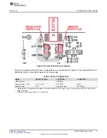
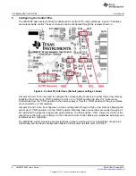
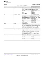
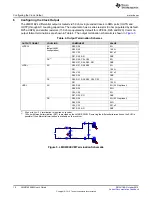
background image

LMK61E2EVM

User's Guide

Literature Number: SNAU188

October 2015

Summary of Contents for LMK61E2EVM

Page 1: ...LMK61E2EVM User s Guide Literature Number SNAU188 October 2015 ...

Page 2: ...the Clock Output 10 7 Using the USB Interface Connection 11 8 EVM Quick Start Guide 11 9 Recommended Test Instruments 11 10 Example Performance Measurements 12 11 EVM Layout 15 12 EVM Schematic 18 13 EVM Bill of Materials 21 2 Table of Contents SNAU188 October 2015 Submit Documentation Feedback Copyright 2015 Texas Instruments Incorporated ...

Page 3: ...SL Differential Phase Noise 14 9 Top Overlay 15 10 Top Solder Mask 15 11 Layer 1 Top Side 15 12 Layer 4 Bottom Side View From Bottom 16 13 Bottom Solder Mask 16 14 Bottom Overlay 16 15 Drill Drawing 17 List of Tables 1 Ordering Information 4 2 Power Configurations 7 3 Control Pin Interfaces 9 4 Output Termination Schemes 10 5 Recommended Device Configurations 11 6 Typical Output RMS Jitter Summary...

Page 4: ... Figure 1 LMK61E2EVM Photo Table 1 Ordering Information EVM ID DEVICE ID DEVICE PACKAGE LMK61E2EVM LMK61E2 SIA 5 mm x 7 mm 8 pin QFM SIA 4 LMK61E2EVM User s Guide SNAU188 October 2015 Submit Documentation Feedback Copyright 2015 Texas Instruments Incorporated ...

Page 5: ... boards A software graphical user interface GUI platform can be installed on a Host PC to access the LMK61E2 s device registers and EEPROM via the on board USB to I2 C interface 2 Features Integrated low noise 50 MHz tunable crystal Fine frequency margining in ppm steps via I2 C Coarse frequency margining in percentage steps via I2 C Configurable output format of either LVPECL LVDS or HCSL Program...

Page 6: ...out 4 Configuring the Power Supply The LMK61E2 features a single VDD supply pin that operates from 3 3V 5 This supply can be powered directly from an external supply or through an on board LDO regulator Although the LMK61E2 has integrated LDO regulators for excellent power supply ripple rejection PSRR the EVM s on board regulator U2 can allow a higher supply voltage like 5 V to power the EVM The d...

Page 7: ...E EXTIN VOLTAGE J2 SETTING 1 J3 SETTING 1 USB Powered 2 USB PWR External Power LDO 4 3 V to 5 5 V EXT PWR REG External Power 3 3 V Remove Jumper EXT PWR 1 Markings left of J2 indicate the orientation of jumper settings EXT PWR pins 1 and 2 of jumper and USB PWR REG pins 2 and 3 of jumper 2 USB cable must be connected to J1 for operation 7 SNAU188 October 2015 LMK61E2EVM User s Guide Submit Documen...

Page 8: ...e ground plane are connected by 4 7 kΩ resistors Jumpers J5 and J6 can be configured in a static configuration through a high or low state by strapping the center pin to VDD position or to the GND position Similarly these connections are made through a 4 7 kΩ resistor to the respective supply and ground planes The third position U2A allows for control of the respective control pins over software v...

Page 9: ...s An I2 C master device can interface with the LMK61E2 over the I2 C clock line SCL and data line SDA The open drain topology of the SCL and SDA pins require an external pull up resistor J9 and J10 should always be set in the VDD position to ensure proper I2 C communication The SCL and SDA lines are connected with the onboard microcontroller which is controlled by the GUI J1 USB not shown in Figur...

Page 10: ...MAT COUPLING COMPONENT VALUE LVPECL AC R25 R28 0 Ω default EVM R26 R29 150 Ω configuration C24 C25 0 01 uF R27 R30 R31 DNP DC 1 R25 R28 C24 C25 0 Ω R26 R27 R29 R30 R31 DNP LVDS 2 AC R25 R27 R28 R30 0 Ω R31 100 Ω C24 C25 0 01 uF R26 R29 DNP DC R25 R27 R28 R30 C24 C25 0 Ω R31 100 Ω HCSL AC R25 R28 0 Ω 22 Ω optional R26 R29 50 Ω C24 C25 0 Ω R27 R30 R31 DNP DC R25 R28 0 Ω 22 Ω optional R26 R29 50 Ω C2...

Page 11: ...can be seen on LED D4 active with activity 4 Refer to Table 5 for recommended device configurations configurable via the GUI Table 5 Recommended Device Configurations 1 PARAMETER 156 25 MHz 2 100 MHz 161 1328125 MHz PLL Reference Doubler Enabled N Divider 50 48 51 Fractional Numerator 22500 Fractional Denominator 40000 VCO frequency 5000 MHz 4800 MHz 5162 25 MHz Output Divider 32 16 32 Loop Filter...

Page 12: ...utput RMS Jitter Summary Output Frequency Output Format 1 RMS Jitter fs 12k 20M band Reference Plot spurs off 156 25 MHz LVPECL 90 Figure 6 LVDS 100 Figure 7 HCSL 100 161 1328125 MHz LVPECL 150 LVDS 150 HCSL 150 Figure 8 1 All measurements are AC coupled with recommended board terminations as in Table 4 Figure 6 156 25 MHz LVPECL Differential Phase Noise 12 LMK61E2EVM User s Guide SNAU188 October ...

Page 13: ...om Example Performance Measurements Figure 7 156 25 MHz LVDS Differential Phase Noise 13 SNAU188 October 2015 LMK61E2EVM User s Guide Submit Documentation Feedback Copyright 2015 Texas Instruments Incorporated ...

Page 14: ...rformance Measurements www ti com Figure 8 161 1328125 MHz HCSL Differential Phase Noise 14 LMK61E2EVM User s Guide SNAU188 October 2015 Submit Documentation Feedback Copyright 2015 Texas Instruments Incorporated ...

Page 15: ...ayout 11 EVM Layout Figure 9 Top Overlay Figure 10 Top Solder Mask Figure 11 Layer 1 Top Side 15 SNAU188 October 2015 LMK61E2EVM User s Guide Submit Documentation Feedback Copyright 2015 Texas Instruments Incorporated ...

Page 16: ...Figure 12 Layer 4 Bottom Side View From Bottom Figure 13 Bottom Solder Mask Figure 14 Bottom Overlay 16 LMK61E2EVM User s Guide SNAU188 October 2015 Submit Documentation Feedback Copyright 2015 Texas Instruments Incorporated ...

Page 17: ...www ti com EVM Layout Figure 15 Drill Drawing 17 SNAU188 October 2015 LMK61E2EVM User s Guide Submit Documentation Feedback Copyright 2015 Texas Instruments Incorporated ...

Page 18: ...y Note ZZ3 These assemblies must be clean and free from flux and all contaminants Use of no clean flux is not acceptable Assembly Note ZZ4 These assemblies must comply with workmanship standards IPC A 610 Class 2 unless otherwise specified Assembly Note ZZ5 Default Shunt settings SH1_2 3 means short Pins 2 3of J2 jumper For 3 way jumpers Pin 4 is the 1 pin header Assembly Note ZZ6 Default Shunt se...

Page 19: ...only I2CPU V18 EXT5V_EN EXT5V_FAULT EXT3 3V_EN EXT3 3V_FAULT 0 1µF C15 100k R16 2200pF C16 33k R15 U2A_3V3 D_N D_P 1 2 24MHz Y1 ECS 240 20 5PX TR 33k R5 VCORE SDA SCL 0 R10 0 R11 U2A_GPIO4 U2A_GPIO5 0 R12 0 R13 USER NOTE De populate the 0 ohm resistors connected to U2A_GPIOx and U2A_3V3 nets before attaching the External USB2ANY module to the USB2ANY Header LAYOUT NOTE Place 0 ohm footprints close...

Page 20: ...MK06001SIA GND SDA SCL VDD OE ADD 1 2 3 4 5 P2 OUTP 1 2 3 4 5 P3 OUTN SH5_2_3 1 2 3 J9 FS0 4 7k R21 VDD 4 7k R23 GND SH6_2_3 1 2 3 J10 FS1 4 7k R22 VDD 4 7k R24 GND 0 01µF C22 GND LABEL PINS 1 VDD 2 JP NAME 3 GND LABEL PINS 1 VDD 2 JP NAME 3 GND LMK61XX 4 7µF C23 GND 0 R27 DNP 100 R31 0 R30 DNP 150 R26 150 R29 EVM Schematic www ti com 20 LMK61E2EVM User s Guide SNAU188 October 2015 Submit Document...

Page 21: ... USB TE Connectivity 1734035 2 1 Type B R A Top Mount SMT J2 J3 J5 J6 Header 100mil 3x1 Gold TH Samtec TSW 103 07 G S 4 J7 J8 Header 100mil 1pos Gold TH Samtec TSW 101 07 G S 2 J9 J10 Header 100mil 3x1 Tin TH TE Connectivity 5 146278 3 2 P1 P2 P3 Connector End launch SMA 50 Emerson Network Power 142 0701 851 3 ohm SMT PCB1 Printed Circuit Board Any SV601195 1 Q1 MOSFET N CH 50V 0 22A Fairchild Sem...

Page 22: ...quires No Bypass Capacitor 6 pin LLP Pb Free U2 ULTRA LOW NOISE 250 mA Texas Instruments LP5907MFX 3 3 NOPB 1 LINEAR REGULATOR FOR RF AND ANALOG CIRCUITS REQUIRES NO BYPASS CAPACITOR DBV0005A U3 ESD Protection Array for High Texas Instruments TPD4E004DRYR 1 Speed Data Interfaces 4 Channels 40 to 85 degC 6 pin SON DRY Green RoHS no Sb Br U4 Mixed Signal MicroController Texas Instruments MSP430F5529...

Page 23: ...ring the warranty period to the address designated by TI and that are determined by TI not to conform to such warranty If TI elects to repair or replace such EVM TI shall have a reasonable time to repair such EVM or provide replacements Repaired EVMs shall be warranted for the remainder of the original warranty period Replaced EVMs shall be warranted for a new full ninety 90 day warranty period 3 ...

Page 24: ... by Industry Canada to operate with the antenna types listed in the user guide with the maximum permissible gain and required antenna impedance for each antenna type indicated Antenna types not included in this list having a gain greater than the maximum gain indicated for that type are strictly prohibited for use with this device Concernant les EVMs avec antennes détachables Conformément à la rég...

Page 25: ... connecting any load to the EVM output If there is uncertainty as to the load specification please contact a TI field representative During normal operation even with the inputs and outputs kept within the specified allowable ranges some circuit components may have elevated case temperatures These components include but are not limited to linear regulators switching transistors pass transistors cu...

Page 26: ...F REMOVAL OR REINSTALLATION ANCILLARY COSTS TO THE PROCUREMENT OF SUBSTITUTE GOODS OR SERVICES RETESTING OUTSIDE COMPUTER TIME LABOR COSTS LOSS OF GOODWILL LOSS OF PROFITS LOSS OF SAVINGS LOSS OF USE LOSS OF DATA OR BUSINESS INTERRUPTION NO CLAIM SUIT OR ACTION SHALL BE BROUGHT AGAINST TI MORE THAN ONE YEAR AFTER THE RELATED CAUSE OF ACTION HAS OCCURRED 8 2 Specific Limitations IN NO EVENT SHALL T...

Page 27: ...esponsible for compliance with all legal regulatory and safety related requirements concerning its products and any use of TI components in its applications notwithstanding any applications related information or support that may be provided by TI Buyer represents and agrees that it has all the necessary expertise to create and implement safeguards which anticipate dangerous consequences of failur...

Page 28: ...Mouser Electronics Authorized Distributor Click to View Pricing Inventory Delivery Lifecycle Information Texas Instruments LMK61E2EVM ...

Reviews: