background image

Operation Manual – TEXI 781 SERVO 


Operation Manual 


Buttonhole machine 


781 SERVO 


Summary of Contents for 781 SERVO

Page 1: ...Operation Manual TEXI 781 SERVO Operation Manual Buttonhole machine 781 SERVO ...

Page 2: ...tion of the roll into the upper thread at the start of sewing 18 The time when the scissors are opened 19 Adjustment of the limit plate 20 Safety crank adjustment 21 Upper scissors spring pressure 22 Fixed knife position 23 Height of the presser plate 24 Low speed bump position 25 Starting lever and starting ram position 26 Belt adjustment The adjustment of other parts 1 Adjust the position of the...

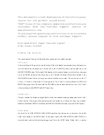
Page 3: ...needle and the hook Adjustment requirements When the needle bar is lifted by 2 3mm from the lowest point the center of the hook tip and the needle should be the same and the upper end of the needle eye is 1 6 1 8mm the lateral gap between the needle and the hook tip is about 0 05mm Adjustment method 1 With the needle bar rising from the lowest point place the positioning scale 2 between the needle...

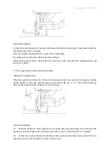
Page 4: ...ft baseline adjustment screw is 10 mm from the upper plane of the baseline adjustment handle and the lower plane of the baseline adjustment handle is exposed to be about 1 mm 2 Position of the right parallel portion The adjustment of the right baseline should be adjusted to the A B position according to the amplitude of the parallel portion Adjustment method 1 Adjustment of the left baseline shoul...

Page 5: ...cent to the parallel portion of the cutter may be biased to the inner side When the amplitude is increased the left parallel portion is individually biased to the left 4 The needle bar cooperation Adjustment requirements 1 When the needle is at the top center the engraved line of the pinion gear should be aligned with the center of the lower shaft 2 If there is no engraving on the pinion gear when...

Page 6: ...e the needle to flow the needle to break and the needle to jump 5 The adjustment of the needle drop for the needle board Adjustment requirements When sewing the parallel portion on the left side the swing fork is at the leftmost end when the needle is lowered to the middle portion of the needle plate hole Adjustment method When the position of the needle bar swing fork is normal and the needle dro...

Page 7: ...ine adjustment shank Note When making this adjustment please remove the spring of this mechanism and adjust it Check if the needle swing cam of the needle spindle gear rotates smoothly The phenomenon when the adjustment value changes If the height of the needle bar swing fork is not accurate the width of the left and right courses will be different 7 The position of the under feeding crank Adjustm...

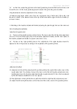
Page 8: ...f the lower crank The phenomenon when the adjustment value changes If the position is wrong whenever the sewing size is changed the action of the scissors will fail and the position of the presser foot will also change causing a broken needle or thread broken 8 Front and rear position of the presser foot Adjustment requirements The gap between the center of the needle drop hole and the inner end s...

Page 9: ...djust the cutter fall time to 2 3 stitches before the sewing machine stops Moving in the direction of the mark the cutter falls early Note When the number of stitches is adjusted to 93 or less adjust the low speed bumps The phenomenon when the adjustment value changes When the cutter is operated during high speed operation the cutter will not fall and the cutter will be accelerated 10 The position...

Page 10: ... The cutter often does not fall down and it is not possible to drop the knife at a low speed It may be that the tension spring of the cutter driving claw is insufficient replace the tension spring 12 Adjustment of the stop device Adjustment requirements The clearance between the stop sub block A and the stop lever block B is 0 2 to 0 5 mm when parked Adjustment method 1 Move the stop block A up an...

Page 11: ...he security hook Adjustment requirements When parking the distance between the start safety hook and the lifter lever is 0 5 0 8mm Adjustment method Adjust with the rotating eccentric shaft screw The phenomenon when the adjustment value changes If there is no gap it will be in a state of conflict causing the presser foot not to return On the contrary if the gap is too large it will not stop 14 The...

Page 12: ...er roller frame Once it is slipped out the presser foot cannot be lifted and the feeding becomes heavy 15 Left and right position of the upper knife Adjustment requirements 1 The upper scissors is aligned with the center of the needle when it advances to the foremost end and the front end of the scissors protrudes 5 mm to the right from the center of the cutter groove 2 When the upper scissors is ...

Page 13: ...erlap between the upper knife and the lower knife The phenomenon when the adjustment value changes 1 When the front back and left and right positions are not good when the presser foot is raised the scissors swing frame is caught and cannot move smoothly 2 The position of the scissors action board A is too far forward to produce the upper line cut continuously scissors are not close together 3 Whe...

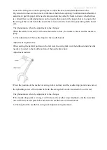
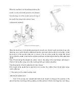
Page 14: ...ever up and down the presser foot and the scissors should not touch each other The phenomenon when the adjustment value changes The position of the scissors is too high and sometimes the thread will remain on the knot 17 The position of the roll into the upper thread at the start of sewing Adjustment requirements At the beginning of the sewing the top end of the upper scissors leaves the center of...

Page 15: ...ustment requirements Adjustment method 1 Loosen the wire head control plate fixing screw and move the control board back and forth to adjust 2 The time to move the control board forward to clamp the upper line is longer and on the contrary it is shortened Confirmation method after adjustment After adjustment turn the manual feed handle you must check that the scissors do not touch the presser foot...

Page 16: ...r shaft screw 2 There should be a gap between the safety lever and the limit plate when parking and upper scissors moving The phenomenon when the adjustment value changes Note After an emergency stop the presser foot should be raised at the needle up position 20 Safety crank adjustment Adjustment method After the upper scissors shaft is pulled away from the thread control board the overlap between...

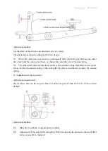
Page 17: ...r scissors edge is not sharp the scissors can be replaced 22 Fixed knife position Adjustment requirements The fixed knife edge is 0 3 0 5mm away from the needle plate hole Adjustment method 1 Loosen the fixed knife fixing screw for the fixed knife adjustment 2 When changing the fixed knife take out the hook finger to replace it The phenomenon when the adjustment value changes The gap between the f...

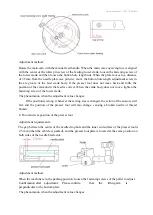
Page 18: ...rmally 24 Low speed bump position Adjustment method Adjust the size of A according to the number of stitches used to loosen the fixing screws of the low speed bumps stitches A size under 93 stitches 10 12mm between 93 123 5mm More than 123 stitches 0 The phenomenon when the adjustment value changes Moving the low speed bumps counterclockwise can reduce the number of stitches from low speed to stop...

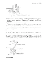
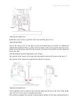
Page 19: ... the belt is exposed from the runner by about 0 5 1mm which is adjusted by the long hole of the starting fork on the nose At low speed the belt should completely cover the drive pulley Note When idling try not to make the belt contact the starter fork on the handpiece The phenomenon when the adjustment value changes When idling if the belt is wrapped around the drive pulley the belt will be easily...

Page 20: ...ther parts 1 Adjust the position of the left and right stitches according to the width of the hole 1 Swing of the needle based on the right side Sew the needle to the left side for sewing In the figure A is the left baseline B is the right baseline W1 is the left and right horizontal amplitude width W2 is the reinforcement amplitude width C is the first reinforcement length first set and D is the ...

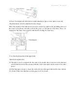
Page 21: ... wire bump on the main cam are rotated in the direction of the arrow to speed up The opposite is slow 3 Adjustment of the wiper When the machine stops the threaded wipe will loosen the upper thread by 5 7mm which can prevent the off line phenomenon when starting the seam When the thread is removed the amount of the thread will increase When adjusting do not touch the first tension and through the ...

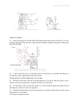
Page 22: ... lower thread clamp spring is pulled to gently press the lower thread 7 Adjustment of the bobbin pressure bar device The bobbin presser device is in synchronous connection with the bottom thread trimming device When the lower thread is plucked the bobbin pressure bar presses the bobbin on the back to prevent idling and at the same time the upper thread remaining on the cloth is pulled down to the ...

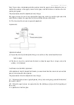
Page 23: ... height CE DECLARATION OF CONFORMITY Distributor Strima Sp z o o Swadzim st Poznańska 54 62 080 Tarnowo Podgórne Polska We declare that the following product TEXI 781 SERVO Buttonhole machine ZJ781 BD which this declaration relates complies with the following directives Machinery directive 2006 42 EC Low voltage directive 2014 35 EU Harmonized norm used EN 60204 3 1 2013 ...

Page 24: ...Operation Manual TEXI 781 SERVO ...

Page 25: ...Operation Manual TEXI 781 SERVO Dealer ...

Reviews: