background image


TEXI XYZ 2518 

MANUAL


Summary of Contents for XYZ 2518

Page 1: ...TEXI XYZ 2518 MANUAL...
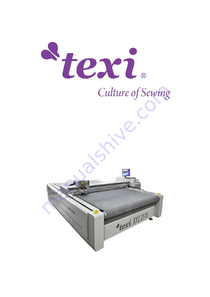
Page 2: ...ation of the Cut Software 13 5 1 Import Processing File 13 5 2 Export the Processing File 15 5 3 SP number 16 5 4 Optimize the Processing Graph 18 5 5 Send Graph to the Machine 19 5 6 Please refer to...

Page 3: ...9Punching Tool SP2 44 7 7 Milling Tool SP6 46 8 Test Angle and Test Offset 47 8 1 Test Angle 48 8 2 Test Offset 49 9 Maintenance 50 1 Machine Introduction 1 1 Power and cable requirements In view of t...

Page 4: ...ing air Box Air Compressor Vacuum pump Control Box Note 1 When 380V voltage is used for power supply only three live wires need to be used and there is no need to use the null wire 2 For models withou...

Page 5: ...r B Connect the three live wires of the 380V three phase electricity to the 1 L1 3 L2 5 L3 of the AC contactor separately Note If the fan reverses the position of two live wires can be changed arbitra...

Page 6: ...iation plug of the 220V Power Cable to the machine or the control box Note Subject to the actual model 2 Vacuum Pump of the Digital Knife Cutting Machine with Flat Table 3 Vacuum Pump and Returning ai...

Page 7: ...the air tube Connect No 5 to the No 7 The outlet of the vacuum pump by the air pipe No 8 is the Hush pipe No 9 is the pressure relief valve it must be installed onto the reducer which is connected to...

Page 8: ...the electricity to the machine and control box and the power of the machine is about 2500W Output A Connect the aviation plug of the Signal Cable to the Air Pump port on the machine B Connect the two...

Page 9: ...vacuum pump Connect No 4 Solenoid valve to the oil water separator Pneumatic valve on the machine by the air tube Connect No 5 to the No 11 by air pipe and connect the No 12 No 13 and No 14 of the Par...

Page 10: ...oduction Cut is a cutting service software for editing and cutting tasks It can be well matched with mainstream graphic design software The software can be used for drawing simple graphs You can also...

Page 11: ...lick Local Area Connection as shown below 2 Click Properties 3 Double click Internet Protocol Version 4 TCP IPV4 4 Click Use the following IP address change the IP as shown below Note There can not be...

Page 12: ...e click to open the software click optimize config P 4 2 the machine work area they must be the same with the data in the panel the machine IP it must be the same with the machine IP Check the cutter...

Page 13: ...ot be changed 4 3 it s used for the auto feeding system 5 Operation of the Cut Software 5 1 Import Processing File 1 Click file open the icons Note The shortcut keys are Ctrl O also can be used to imp...

Page 14: ...terface 3 Change the default opening method of the processing file and then double click the processing file icon to import the processing file into the cut software The steps are as follows Move the...

Page 15: ...not docked at the left bottom corner you can press C key on the keyboard or click in the software to complete the docking operation 5 2 Export the Processing File 1 Click file save or click to save th...

Page 16: ...iversal cutting tool SP5 Small knife V cut tool SP6 Milling tool SP7 Mark point Mark line SP0 Not to process 2 Two cutter heads machine The machine that all same tools holders mounted on two separated...

Page 17: ...the Head1 is SP3 the Pen1 is SP2 the Head2 and Pen2 all are SP0 as shown below When cut the graph which the row number is odd number in bottom row set the Head1 and Pen1 Head1 is SP4 Pen1 is SP1 proce...

Page 18: ...Click or to optimize the cutting path and the cutting effect of the processing graph The content of optimization operation execution is the following selected contents as shown below Note Click optim...

Page 19: ...e The machine will enter the screen saver interface even if it has not been operated for a long time And it also can enter the screen saver interface manually Note The screen saver interface is used t...

Page 20: ...no clamp and drag function for the non auto feeding model machine 3 This area controls the movement lifting and rotation of the knife tools 4 control the rotation of the knife tools 5 control the lif...

Page 21: ...ates of the cutter head may not be 0 at this time so it is necessary to go to the origin point so as to make the coordinates of the control system consistent with the actual positions of each axis Whe...

Page 22: ...adsorbed because after pressing the repeat button the vacuum pump will work automatically and then the machine will start to process the graph 17 clamp is used to manually control the falling and lift...

Page 23: ...th adjustment of every tool please refer to the 7 Tools Installation and Knife Depth Setting 4 These two area are used to switch the SP number Click the SP number gets smaller Click the SP number gets...

Page 24: ...is button is used to set the height position of the knife tool in the non cutting process of the machine during cutting The range of this number is knife depth up 10 and up material thickness Note The...

Page 25: ...back and delay parameters and so on You can also change the speed and parameters in this page 3 These are the cutting speed data of the corresponding tool during processing these data can be changed...

Page 26: ...and the actual drag distance For example when cutting a square with a side length of 1000mm the theoretical drag distance is 1000mm while the actual drag distance is 990mm the difference between the t...

Page 27: ...nfig is short for configuration 1 Some functions and settings can be set in the config page and the corresponding authorization code can be input according to the main board number displayed on this p...

Page 28: ...to be sent must be a line segment 6 The machine will cut the graph immediately after receiving it After receiving the graph the machine will not cut it automatically Press twice to zero and you can ch...

Page 29: ...he tool up extend It is the processing parameter of the end point of a single continuous processing graph that is the processing parameter of the raise position of the tool The value is bigger than 0...

Page 30: ...essed in times and then press in test page the machine will start to process according to the set times The cut times shows the number of times the processing has been completed Note The number of the...

Page 31: ...ing cutting It means when the cutter head moves to a certain area the current area and the adjacent areas will adsorb the material For example if the cutter is at area out8 the area out8 out9 and out1...

Page 32: ...e tools are installed in the fixed holders for a long time resulting in rust and unable to be taken out 7 1 Oscillating Knife Cutting Tool SP4 cut Head1 1 Grab parts 1 and 2 and then force the cap and...

Page 33: ...shown in the picture is the knife depth set before that is the current knife depth If the distance between the current tool tip and the table top is greater than this number you can press to drop the...

Page 34: ...sition B When the tip of the knife just goes into the felt about 0 5 1mm the tool setting is completed as shown bellow Method Two A Rotate this part of the oscillating knife cutting tool till the knif...

Page 35: ...The value of up also can be set at 0 if it is 0 the tool will rise to the Z axis origin point position when it rises during working Note If need to set the rising height 1 Press the button on the lef...

Page 36: ...adjustment is similar 7 2 Pneumatic Oscillating Cutting Tool SP4 cut Head1 1 The knife must be placed at the bottom of the groove and the cutting edge is at the same side with the set screws 2 Make s...

Page 37: ...try cutting If the knife depth is slightly shallow or too deep the knife depth can be fine tuned according to the 7 1 6 4 Over cutting the over cutting is controlled by extension Extension is divided...

Page 38: ...art of the tip is the same as or slightly less than the thickness of the cutting material 2 Make sure that the value of the W axis is 0 00 and the cutting edge of the knife must face the X direction t...

Page 39: ...effect if the cutting effect is not achieved it is necessary to fine tune the missing part of the tip or the knife depth data in the panel 7 6 Creasing Wheel Tool SP2 Tcut Head2 1 Introduction to the...

Page 40: ...represents the distance that the creasing wheel continues to fall on the basis of the set knife depth For example the current knife depth of the creasing wheel tool is 30 the heavy add is 1 and the a...

Page 41: ...direction tighten the fixing ring and set screws The method to tighten the set screw which is at the X position please refer to 7 6 2 Debugging It is recommended to use corrugated paper for debugging...

Page 42: ...meter till it can cut like this E Press The machine will cut two transverse lines in the Y direction If the two lines do not coincide press to fine tune its parameter till the two lines coincide Knife...

Page 43: ...r debugging A Put the corrugated paper on the felt B Press the buttons and the parameters must be set as below the parameters of them must be 0 00 Set the knife depth by yourself please just let the t...

Page 44: ...on can coincide G When use the small knife V cut tool to cut the material the SP number is SP5 and it needs to set Only the up parameter knife depth speed parameter and extend parameter can be changed...

Page 45: ...depth of the punching tool is not suitable you can adjust the nut on the top of the punching tool to fine tune the depth of the punching tool as shown below 4 Test offset the V knife and round knife s...

Page 46: ...in the processing file is less than 50mm you need to select the circles which need to be punched in the processing file then change their SP number to SP2 as shown below 7 7 Milling Tool SP6 1 Vacuum...

Page 47: ...5 After the installation is completed and when set the knife depth just let the end of the milling cutter contact with the felt 8 Test Angle and Test Offset Note Testing angle is taking the oscillatin...

Page 48: ...on the material 2 Before testing angle a piece of material should be laid first such as corrugated paper KT board soft glass etc 1 Test Angle Press to change it to Press the oscillating knife cutting...

Page 49: ...he angle of the knife still is wrong just need to adjust the angle again till the tool can cut a cross as shown below 8 2 Test Offset Note Before testing the offset the knife depth and the angle must...

Page 50: ...rag Check the drag chain slot Make sure that the drag chain slot is free of sundries and noise Check the operation in the X and Y directions Running without any noise before cutting Clean the X and Y...

Page 51: ...sors are no loose and no dust Check bearings conditions Confirm no bearings loose Check cable and wires Confirm whether they are connected firmly Clean the distribution box Clean it with the vacuum cl...

Reviews: