

READ AND SAVE THESE INSTRUCTIONS
WARNING - TO REDUCE THE RISK
WARNING - TO REDUCE THE RISK
WARNING - TO REDUCE THE RISK
WARNING - TO REDUCE THE RISK
WARNING - TO REDUCE THE RISK
OF FIRE, ELECTRIC SHOCK, OR
OF FIRE, ELECTRIC SHOCK, OR
OF FIRE, ELECTRIC SHOCK, OR
OF FIRE, ELECTRIC SHOCK, OR
OF FIRE, ELECTRIC SHOCK, OR
INJURY TO PERSONS, OBSERVE
INJURY TO PERSONS, OBSERVE
INJURY TO PERSONS, OBSERVE
INJURY TO PERSONS, OBSERVE
INJURY TO PERSONS, OBSERVE
THE FOLLOWING:
THE FOLLOWING:
THE FOLLOWING:
THE FOLLOWING:
THE FOLLOWING:
CAUTION: FOR GENERAL VENTI-
CAUTION: FOR GENERAL VENTI-
CAUTION: FOR GENERAL VENTI-
CAUTION: FOR GENERAL VENTI-
CAUTION: FOR GENERAL VENTI-
LATING USE ONLY.
LATING USE ONLY.
LATING USE ONLY.
LATING USE ONLY.
LATING USE ONLY. DO NOT
DO NOT
DO NOT
DO NOT
DO NOT USE
USE
USE
USE
USE
TO EXHAUST HAZARDOUS OR
TO EXHAUST HAZARDOUS OR
TO EXHAUST HAZARDOUS OR
TO EXHAUST HAZARDOUS OR
TO EXHAUST HAZARDOUS OR
EXPLOSIVE MATERIALS OR VA-
EXPLOSIVE MATERIALS OR VA-
EXPLOSIVE MATERIALS OR VA-
EXPLOSIVE MATERIALS OR VA-
EXPLOSIVE MATERIALS OR VA-
PORS.
PORS.
PORS.
PORS.
PORS.
A. Use this unit only in the manner
intended by the manufacturer. If
you have questions, contact the
manufacturer.
B. Before servicing or cleaning the
unit, switch power off at service
panel and lock service panel
disconnecting means to prevent
power from being switched on
accidentally. When the service
disconnecting means cannot be
locked, attach a tag to the service
panel to indicate power has been
switched off for maintenance.
INSTALLATION INSTRUCTIONS
PHE WALL HOOD
APPROVED FOR ALL
RESIDENTIAL APPLIANCES
FOR RESIDENTIAL USE ONLY
IMPORTANT SAFETY INSTRUCTIONS
IMPORTANT SAFETY INSTRUCTIONS
IMPORTANT SAFETY INSTRUCTIONS
IMPORTANT SAFETY INSTRUCTIONS
IMPORTANT SAFETY INSTRUCTIONS
PLEASE READ ENTIRE INSTRUCTIONS BEFORE PROCEEDING.
PLEASE READ ENTIRE INSTRUCTIONS BEFORE PROCEEDING.
PLEASE READ ENTIRE INSTRUCTIONS BEFORE PROCEEDING.
PLEASE READ ENTIRE INSTRUCTIONS BEFORE PROCEEDING.
PLEASE READ ENTIRE INSTRUCTIONS BEFORE PROCEEDING.
INST
INST
INST
INST
INSTALLA
ALLA
ALLA
ALLA
ALLATION MUST COMPL
TION MUST COMPL
TION MUST COMPL
TION MUST COMPL
TION MUST COMPLY Y Y Y Y WITH
WITH
WITH
WITH
WITH ALL LOC
ALL LOC
ALL LOC
ALL LOC
ALL LOCAL CODES.
AL CODES.
AL CODES.
AL CODES.
AL CODES.
IMPORTANT:
IMPORTANT:
IMPORTANT:
IMPORTANT:
IMPORTANT:
Save these Instructions for the Local Electrical Inspector’s use.
INSTALLER:
INSTALLER:
INSTALLER:
INSTALLER:
INSTALLER:
Please leave these Instructions with this unit for the owner.
OWNER:
OWNER:
OWNER:
OWNER:
OWNER:
Please retain these instructions for future reference.
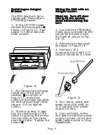
Safety Warning: Turn off power circuit at service panel and lock out panel,
Safety Warning: Turn off power circuit at service panel and lock out panel,
Safety Warning: Turn off power circuit at service panel and lock out panel,
Safety Warning: Turn off power circuit at service panel and lock out panel,
Safety Warning: Turn off power circuit at service panel and lock out panel,
before wiring this appliance.
before wiring this appliance.
before wiring this appliance.
before wiring this appliance.
before wiring this appliance.
Requirement: 120 V AC, 60 Hz. 15 or 20 A
Requirement: 120 V AC, 60 Hz. 15 or 20 A
Requirement: 120 V AC, 60 Hz. 15 or 20 A
Requirement: 120 V AC, 60 Hz. 15 or 20 A
Requirement: 120 V AC, 60 Hz. 15 or 20 A
FILE # E21958
LI06EC Ed. 10/98
C. Installation Work and Electrical
Wiring Must Be Done By
Qualified Person(s) In Accor-
dance With All Applicable
Codes & Standards, Including
Fire-rated Construction.
D. Sufficient air is needed for
proper combustion and ex-
hausting of gases through the
flue (chimney) of fuel burning
equipment to prevent back-
drafting. Follow the heating
equipment manufacturers
guideline and safety standards
such as those published by the
National Fire Protection Asso-
ciation (NFPA), the American
Society for Heating, Refrigera-
tion and Air
Conditioning
Engineers
(ASHRAE), and
the local code
authorities.


