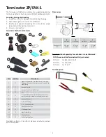
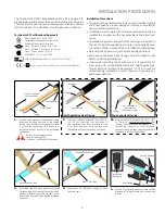
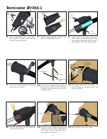
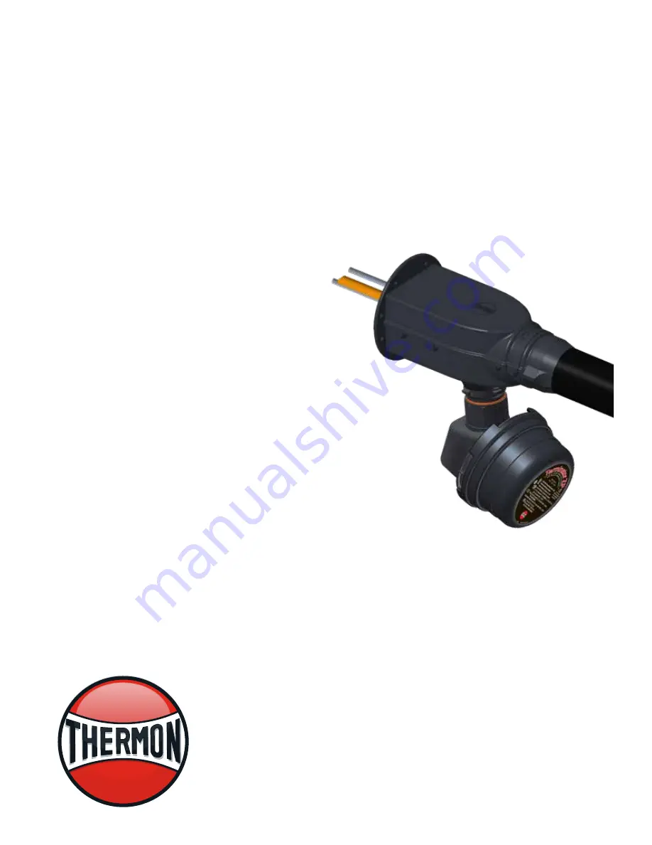
Thermon Terminator ZP/FAK-1, Installation Procedures
The Thermon Terminator ZP/FAK-1 is a state-of-the-art thermal protection system for industrial settings. Ensure a seamless and efficient installation with our comprehensive user manual that provides detailed installation procedures. Download this indispensable manual for free from our website 88.208.23.73:8080, and experience the full potential of this exceptional product.
Share
Download


Reviews:
No comments
Related manuals for Terminator ZP/FAK-1

MIL-L100S
Brand: MiLAN Pages: 10

RC-202iPV
Brand: Sony Pages: 2

88757
Brand: Gearwrench Pages: 3

10.25.0002
Brand: Nanocable Pages: 6

ESKE-L 12 Series
Brand: WISKA Pages: 8

NAMSR-5W-120
Brand: Warmup Pages: 11

LightCrimp Plus ST
Brand: CommScope Pages: 16

ION-M7P
Brand: CommScope Pages: 50

opticalCON DRAGONFLY NKO2S-XP Series
Brand: NEUTRIK Pages: 4

POF/UAE 1xUp 0
Brand: Rutenbeck Pages: 4

38370-8
Brand: Lindy Pages: 4

CLUX-8M3D
Brand: Cypress Pages: 5

SolConeX 8573/12 Series
Brand: Stahl Pages: 34

DF63 Series
Brand: HRS Pages: 6

DA-80
Brand: Ahuja Pages: 12

B frame
Brand: Roxtec Pages: 4

PXI-1042HVDC
Brand: National Instruments Pages: 2

APP SBE 320
Brand: IDEAL Pages: 4


