background image

Owner’s Manual

For professional use only

Do not use this equipment before reading this manual!
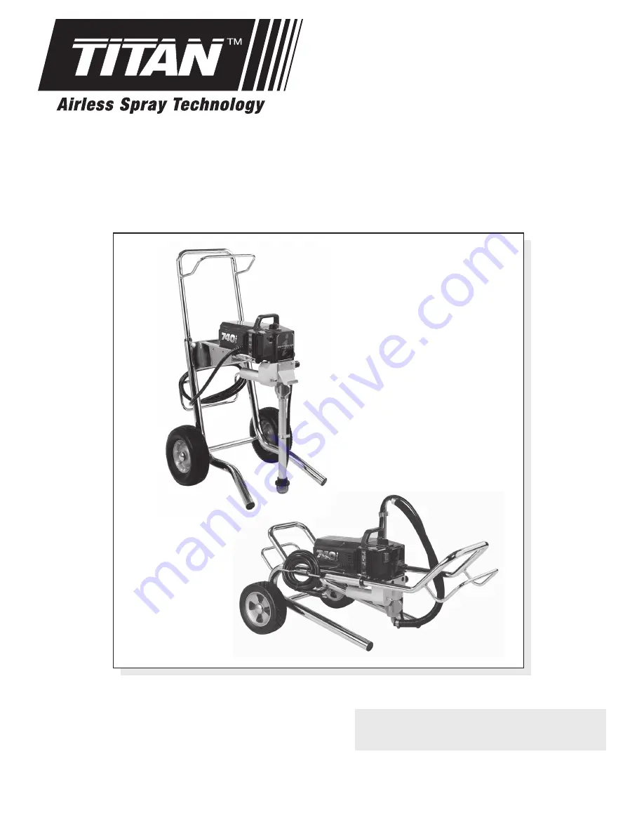
740

i

Airless Sprayer

Model Numbers:
 

High Rider Bare 

800-120


High Rider Complete 

800-121


Low Rider Bare 

800-122


Low Rider Complete 

800-123

Printed in USA

0808

 •


© Titan Tool Inc.  All Rights Reserved.  Form No. 313-1695C

 NOTE:  This manual contains important warnings 

and instructions.  Please read and retain for 

reference.

Summary of Contents for 740i

Page 1: ...irless Sprayer Model Numbers High Rider Bare 800 120 High Rider Complete 800 121 Low Rider Bare 800 122 Low Rider Complete 800 123 Printed in USA 0808 Titan Tool Inc All Rights Reserved Form No 313 1695C NOTE This manual contains important warnings and instructions Please read and retain for reference ...

Page 2: ...e injury as soon as possible DO NOT delay treatment to research toxicity Toxicity is a concern with some coatings injected directly into the blood stream Consultation with a plastic surgeon or reconstructive hand surgeon may be advisable HAZARD HAZARDOUS VAPORS Paints solvents insecticides and other materials can be harmful if inhaled or come in contact with the body Vapors can cause severe nausea...

Page 3: ... not overreach or stand on an unstable support Keep effective footing and balance at all times Use lowest possible pressure to flush equipment Stay alert and watch what you are doing Do not operate the unit when fatigued or under the influence of drugs or alcohol For electric units Always unplug cord from outlet before working on equipment Do not use the hose as a strength member to pull or lift t...

Page 4: ...e gun and one on the hose tighten securely NOTE Do not attach the tip to the spray gun yet Remove the tip if it is already attached Make sure all airless hoses and spray guns are electrically grounded and rated for at least 3300 psi 22 8 MPa fluid pressure 4 Make sure the pressure control knob is in its OFF position in the black zone 5 Make sure the ON OFF switch is in its OFF position 6 Fill the ...

Page 5: ...ray system changing or cleaning spray tips or preparing for cleanup Painting 1 Place the siphon tube into a container of paint 2 Place the return hose into a metal waste container Max PSI Clean Min PSI 3 Set the pressure to minimum by turning the pressure control knob to the Min setting in the yellow zone 4 Move the PRIME SPRAY valve down to the PRIME position 5 Turn on the sprayer by moving the O...

Page 6: ...ser to the surface deposits more paint on the surface and produces a narrower spray pattern Holding the gun farther from the surface produces a thinner coat and wider spray pattern If runs sags or excessive paint occur change to a spray tip with a smaller orifice If there is an insufficient amount of paint on the surface or you desire to spray faster a larger orifice tip should be selected Maintai...

Page 7: ... its SPRAY position 11 Turn on the sprayer Ground the gun by holding it against the edge of the metal container while flushing Failure to do so may lead to a static electric discharge which may cause a fire 12 Trigger the gun into the metal waste container until the paint is flushed out of the hose and solvent is coming out of the gun 13 Continue to trigger the spray gun into the waste container u...

Page 8: ...f the baffle assembly and slip the baffle assembly off of the motor Remove the four baffle spacers 4 Slide the electronic cover off of the electronic control assembly on the motor 5 Loosen and remove the four heat sink assembly mounting screws Pull back the heat sink assembly to access and disconnect the two wires coming from the motor 6 At the electronic control assembly a Disconnect the white wi...

Page 9: ...r heat sink assembly mounting screws 18 Slip the baffle assembly around the motor Secure the baffle assembly with the baffle tape Slip the four baffle spacers into position between the rear bell of the motor and the baffle assembly 19 Slide the motor shroud over the motor Make sure the housing gasket is positioned properly 20 Secure the motor shroud with the four motor shroud screws Replacing the ...

Page 10: ...e bottom of the foot valve housing Unscrew the return hose from the pump block and remove the suction set assembly 5 Tilt the pump back for easy access to the fluid section Foot Valve Housing Foot Valve Seat Foot Valve Ball Lower Seal Lower Cage Adapter Pump Block O Ring Servicing the Valves The design of Titan s fluid section allows access to the foot valve and seat as well as the outlet valve an...

Page 11: ...if necessary NOTE Coat the piston guide tool and the piston rod with grease before inserting them into the pump block 16 Place the piston insertion tool included in the repacking kit over the top of the piston rod 17 Insert the piston rod into the bottom of the pump block through the lower packing through the upper packing and out through the retainer nut Using a rubber mallet tap the bottom of th...

Page 12: ...n or re tape the connection with PTFE tape 3 Remove the pump filter element and clean Remove the inlet screen and clean 4 Remove the siphon tube suction set and clean 1 Replace the spray tip following the instructions that came with the spray gun 2 Replace the spray tip with a tip that has a smaller orifice following the instructions that came with the spray gun 3 Turn the pressure control knob cl...

Page 13: ... Titan Tool Inc All rights reserved 13 Notes ...

Page 14: ...en ou un spécialiste en chirurgie reconstructive de la main DANGER ÉMANATIONS DANGEREUSES Certains produits peintures solvants insecticides ou autres peuvent être nocifs s ils sont inhalés ou entrent en contact avec l organisme Les émanations de ces produits peuvent provoquer de graves nausées évanouissements ou empoisonnements MESURES PRÉVENTIVES Se servir d un masque ou d un respirateur s il y a...

Page 15: ...r des vêtements aptes à protéger la peau et les cheveux du produit utilisé Ne pas utiliser le pistolet ou ne pas pulvériser de produits en présence d enfants à proximité Éloigner les enfants de l équipement en tout temps Ne pas s étirer ni ne travailler sur un support instable Toujours garder les deux pieds au sol pour rester en équilibre Se servir de la pression la plus basse possible pour vidang...

Page 16: ...os revestimientos inyectados directamente en la corriente sanguínea Puede ser aconsejable consultar con un cirujano plástico o un cirujano especialista en reconstrucción de las manos PELIGRO VAPORES PELIGROSOS Las pinturas solventes insecticidas y demás materiales pueden ser nocivos si se inhalan o toman contacto con el cuerpo Los vapores pueden causar náuseas graves desmayos o envenamiento PREVEN...

Page 17: ...n todo momento No se asome ni se pare sobre soportes inestables Mantenga siempre la posición firme y el equilibrio efectivos Use la presión más baja posible para enjuagar el equipo Manténgase alerta y mire lo que hace No utilice la unidad cuando se encuentre cansado o bajo la influencia de las drogas o el alcohol Para las aparatos eléctricas Desenchufe siempre el cable antes de trabajar en el equi...

Page 18: ...ing 1 3 Fluid section assembly see separate listing 1 4 763 552 Lock washer 2 5 710 033 Screw 2 6 704 304 Pail hook 1 7 730 334 Hose clamp 1 Item Part Description Quantity 8 705 054 Siphon tube High Rider 1 9 710 046 Inlet screen 10 mesh High Rider 1 10 704 117 Screw 2 11 Motor assembly see separate listing 1 12 761 178 Screw 4 13 800 915 PRIME SPRAY valve assembly 1 14 702 239 Return hose High Ri...

Page 19: ... 10 800 215 Fan shroud 1 11 800 294 Fan assembly 1 12 800 427 Baffle assembly 1 13 800 416 Baffle tape 1 14 800 439 Baffle spacer 4 Titan Tool Inc All rights reserved 19 Motor Assembly Electrical Schematic Transducer 800 101 Potentiometer 800 461 Power Cord 800 079 HR 800 029 LR Ground Chassis Plug BLACK GREEN WHITE WHITE RED BLACK BLUE GRAY PURPLE YELLOW WHITE BLACK Electronic Control Assy Indica...

Page 20: ...20 Titan Tool Inc All rights reserved Gear Box Assembly 2 1 3 4 5 6 7 10 11 8 9 12 13 14 18 2 19 20 15 16 17 ...

Page 21: ...tion Quantity 1 800 463 Handle includes items 2 6 and 11 1 2 590 506 Washer 2 3 590 508 Roll pin 2 4 590 504 Sleeve 2 5 856 921 Screw 4 6 856 002 Washer 4 7 704 291 Roll pin 2 8 704 354 Spacer 2 9 704 355 Cap 2 10 800 462 Frame includes items 13 and 15 1 11 590 507 Snap button 2 12 761 178 Hex head screw 4 13 710 199 Plug 2 14 800 593 Wheel 2 15 335 018 Plug 2 Low Rider Cart Assembly P N 705 200 5...

Page 22: ...32 33 34 35 36 38 37 39 40 41 Install upper packing with raised lip and o ring facing down O Ring Raised Lip NOTE When using HOT solvents replace Viton o ring item 36 with optional PTFE o ring P N 700 897 Install with o ring tool P N 700 890 Install lower packing with the side that has the o ring closest to the top of the packing facing up Closer Top ...

Page 23: ...y 27 702 251 Adapter 1 28 757 105 Filter support spring 1 29 704 297 O ring 1 30 800 915 PRIME SPRAY valve assembly includes items 31 43 1 31 700 537 Gasket 1 32 221 012 O ring Viton 1 33 222 012 O ring PTFE 1 34 700 253 Valve housing 1 35 800 910 Valve seat 1 36 700 721 O ring Viton 1 700 897 O ring PTFE optional 37 700 750 Valve stem 1 38 800 926 Spring 1 39 700 248 Valve retainer 1 40 700 251 C...

Page 24: ...NY CLAIM FOR BREACH OF THESE WARRANTIES Material Safety Data Sheets MSDS are available on Titan s website or by calling Customer Service United States Sales Service 1770 Fernbrook Lane Minneapolis MN 55447 www titantool com 200 Trowers Road Unit 7B Woodbridge Ontario L4L 5Z8 Tech Service Order Entry Fax Order Entry Fax Tech Service 1 800 526 5362 1 800 528 4826 1 800 525 9501 Phone Fax 1 800 565 8...

Reviews: