
TJERNLUND PRODUCTS, INC.
1601 Ninth Street • White Bear Lake, MN 55110-6794
PHONE (800) 255-4208 • (651) 426-2993 • FAX (651) 426-9547
Visit our web site • www.tjernlund.com
READ OWNERS INSTRUCTIONS CARE-
FULLY PRIOR TO INSTALLATION.
THESE INSTRUCTIONS MUST REMAIN
WITH EQUIPMENT. DO NOT DESTROY.
AIRESHARE
TM
ROOM-TO-ROOM TRANSFER FAN
MODEL AS2
©2014 TJERNLUND PRODUCTS, INC. ALL RIGHTS RESERVED
P/N: 8504213
DESCRIPTION
The Tjernlund AireShare™ Room-to-Room Transfer fans distribute air from one conditioned space to another. Virtually every home has
a room that is uncomfortably hot or cold from which some of that room’s air can be shared with an adjacent room, making the tempera-
ture of both rooms more comfortable. The AireShare™ transfers air through the wall cavity created between two wall studs. The
AireShare’s unique option of moving the air up or down within the wall cavity allows for optimum heat transfer between rooms. In addi-
tion, locating the Grille and Diffuser, one high the other low, prevents the transfer of light and sound between these adjacent rooms.
AS2 SPECIFICATIONS & COMPONENTS
GENERAL INFORMATION
Every Tjernlund AireShare™ Room-to-Room Transfer fan is electrically factory line tested before shipment.
After opening carton, inspect thoroughly for shipping damage. Impeller should rotate freely and all electrical wires and connections
should be secured. If any damage is found, notify freight carrier and your distributor immediately and file a concealed damage claim.
SPEED SELECTION ADVICE
Since it is impractical to calculate heating and cooling loads for the variety of geographic areas, construction methods and the tempera-
ture of transferred air we base our model selection advice on providing a minimum of 3 Air Changes/Hour (ACH) to the target room.
Door under-cuts or pressure relief transfer grilles in the target room are necessary for proper AireShare performance.
(AireShare CFM x 60) / (L x W x H of target room) = ACH
NOTE:
Aireshare CFM is 110 on High, 95 on Med and 80 on Low
3-4 Air Changes/hour (ACH) recommended for best temperature equalization.
4-5 Air Changes/hour (ACH) recommended for rooms with high cooling or heating loads. Examples include rooms with extensive out-
side walls, windows, over tuck under garages or in extreme climates. More than one AireShare transfer fan can be installed to reach
desired number of air changes for large spaces.
INSTALLATION RESTRICTIONS
The AireShare™ Transfer fan must be installed by a qualified installer in accordance with these instructions and all local codes, includ-
ing fire-rated construction. In their absence, install in accordance with the latest editions of the International Residential Code and
International Electrical Code. Improper installation can create a hazardous condition such as fire, electric shock or personal injury. To
reduce these risks significantly, use this device only in the manner intended by the manufacturer. If you have questions about proper
usage of this device, call Tjernlund.
Always disconnect the AireShare™ Transfer fan from its power source before installation and servicing.
IMPORTANT:
An in depth investigation of the wall layout is required prior to installation. Avoid a stud wall section that is a path for
plumbing supply lines, drains and vents. Avoid a stud wall section that is insulated or being used as a return air duct for a forced air
system. If stud walls are constructed with metal studs, order Tjernlund Model DK2 Duct Kit or seal all metal stud openings.
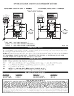
Blower:
3 Speed: 110 CFM, 95 CFM, 80 CFM (Wire for desired speed upon install or use optional AS2SW3 3-speed switch kit.)
Motor:
120 Volts ~ 60 Hz ~ Thermal Switch Protected (Moter Protection Thermique)
0.50 amps maximum, Watts (30 High, 21 Med,16 Low)
Impeller:
Dual Inlet, Low RPM
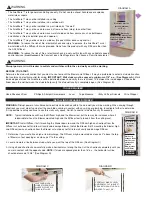
Dimensions: Diffuser:
3” x 15 1/8” (flush)
Diffuser Rough Opening: 1 1/4” High x 13 5/8” Wide
Blower Grille:
16” x 10” x 2 1/2”
Blower Rough Opening:
7 1/4” High x 14 1/2” Wide
Color:
Neutral White


