background image


Toledo Transducers 

PLS-601


Programmable Limit Switch System 

User's Manual 


Rev. 1

Summary of Contents for PLS-601

Page 1: ...Toledo Transducers PLS 601 Programmable Limit Switch System User s Manual Rev 1 ...

Page 2: ... TRANSDUCER 14 4 1 2 MOUNTING THE CONTROL UNIT 14 4 1 3 CONNECTING THE RESOLVER TO THE CONTROL UNIT 14 4 1 4 MOUNTING THE RELAY BOARDS 15 4 1 5 INSTALLING THE AC POWER CORD 15 4 1 6 POWERING ON THE CONTROL UNIT 15 4 2 PLS 601 PROGRAMMING 16 4 2 1 CHANGE PROGRAM NUMBER 17 4 2 2 POSITON TACHOMETER 17 4 2 3 SET 18 4 2 4 OFFSET 22 4 2 5 SCALE FACTOR 23 4 2 6 MOTION DETECT 24 4 2 7 TEACH 26 4 2 8 COPY ...

Page 3: ... 2 MEMORY FULL CONDITION 38 5 3 SELECTING THE NUMBER OF TURNS MASTER MODE 38 5 4 USING THE STANDARD FUNCTIONS PROGRAM DISPLAY 39 5 4 1 POWER ON 39 5 4 2 POS TACH 39 5 4 3 SET 39 5 4 4 OFFSET 40 5 4 5 SCALE 40 5 4 6 MOTION 40 5 4 7 TEACH 40 5 4 8 COPY 41 5 4 9 SPECIAL FUNCTION F7 41 5 4 10 SPECIAL FUNCTION F8 41 5 4 11 END 41 ...

Page 4: ...that comes into actual contact with the switch is often known as the LOBE The design of the cam must allow the user to be able to set both the TIMING and DWELL of the LOBE Several cam switch assemblies can be placed on the same shaft to provide independent TIMING and DWELL for a number of different machine functions Each cam switch assembly is commonly known as a CIRCUIT Mechanical cam switches ca...

Page 5: ...NNEL outputs ON and OFF in accordance with the user programmed LOBE data The CHANNEL outputs can be used directly or in conjunction with the INTEGRAL SOLID STATE RELAYS 3 1 TRANSDUCER The TRANSDUCER is a single turn rotary position transducer that is used in conjunction with the Control Unit The TRANSDUCER utilizes a BRUSHLESS RESOLVER which eliminates the reliability problems associated with opti...

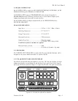
Page 6: ...per turn Consult factory if lower scan times are required Maximum Number of Lobes 3808 238 lobes x 4 channels x 4 groups 3 2 1 ENCLOSURE The CONTROL UNIT ENCLOSURE is constructed of 14 gauge anodized aluminum and is designed for easy access should maintenance or repair be required 3 2 2 PLS 601 FRONT PANEL USER INTERFACE The PLS 601 front panel has been designed for ease of use The front panel uti...

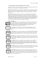
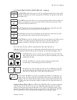
Page 7: ...9 can be entered The ENTER key is used to enter data into non volatile EEPROM memory during execution of the PLS 601 functions The PLS 601 currently supports the following functions The POS TACH function is used to display the selected PROGRAM NUMBER PROG the current resolver angle POSITION P and the current speed of the resolver shaft in RPM R when the function key is active In data entry mode th...

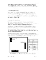
Page 8: ...he PLS 601 memory Following is a functional description of each CURSOR KEYS are used to move the cursor within the various PLS 601 data fields allowing the user to select only those positions at which data entry or data modification is desired The INC and DEC keys are used to modify existing user data by either INCrementing or DECrementing the selected data field The NEXT key is used to display th...

Page 9: ...CONNECTOR a COMMUNICATIONS OUTPUT CONNECTOR and a RELAY OUTPUT BOARD connector These connectors are located on the bottom side of the CONTROL UNIT ENCLOSURE as shown in FIGURE 3 2 5 The TRANSDUCER INTERFACE CONNECTOR is an eight pin male connector used to interface the CONTROL UNIT to the TRANSDUCER Refer to SECTION 3 3 for complete details on the TRANSDUCER INTERFACE The COMMUNICATIONS OUTPUT CON...

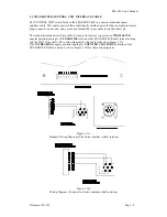
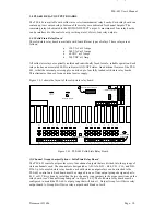
Page 10: ...The standard transducer interface cable is wired at the factory to provide an INCREASING angular position reading for CLOCKWISErotation of the TRANSDUCER shaft when looking into the END of the shaft The wiring diagram for this cable is shown in Figure 3 3A If an INCREASING angular position reading for COUNTER CLOCKWISE rotation of the TRANSDUCER shaft is desired refer to Figure 3 3B for that wirin...

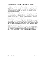
Page 11: ... shows the layout of the solid state relay board MD 1 2 3 4 5 6 7 8 9 10 11 12 13 14 15 16 ENA 1 2 3 4 5 1 2 3 4 5 P102 P101 6 1 MD 2 3 4 5 9 7 8 10 11 12 13 16 14 15 A B C D I N P D H C H B H A H D L C L B L A L P 1 0 0 A P 1 0 0 B 16 ERR INT EXT ENABLE 1 Channel Group Jumpers 2 Interface Connectors Relay 16 Jumper 4 Relay Output Connectors 3 1 2 3 2 1 3 5 Output Enable Connector Figure 3 4 1 PLS...

Page 12: ... Unit The solid state relay output connectors are labeled 1 through 16 In addition a 2 pin connector is available for the MOTION DETECT function This connector is labeled MD 4 Relay 16 Jumper Options Solid State Relay Board Solid state Relay 16 may be used as one of the standard channel output relays or it may be used as an indication that an error has occurred in the PLS 601 Control Unit To enabl...

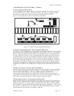
Page 13: ...oards are required an external power supply must be used see DC Power Source for details Each board must be assigned to one of four output groups designated as A B C or D This is done by installing the two channel group jumpers in the proper positions on the relay board see Channel Group Jumpers in Figure 3 4 2 The relay board must be configured to match the PLS 601 output group that will drive it...

Page 14: ...in input connector that implements an OUPTUT ENABLE function see Output Enable Connector in Figure 3 4 2 This connector is labeled ENA The ENA pins must be shorted together in order for any of the seventeen electromechanical relay outputs to be enabled If this connection is opened all seventeen electromechanical relay outputs will be disabled 6 DC Power Source Electromechanical Relay Board The int...

Page 15: ... Unit from contamination caused by water oil dust or corrosive gases The Control Unit should not be subjected to excessive amount of mechanical shock or vibration The mounting location should be chosen such as to avoid exposure to significant levels of electromagnetic interference EMI which can be induced by devices such as motor starters and control relays The operating temperature must be mainta...

Page 16: ...mounts of mechanical shock or vibration The mounting location should not be exposed to extreme levels of electromagnetic interference EMI that can be induced by devices such as motor starters and control relays The operating temperature of the relay boards has been rated at 32 F to 125 F 4 1 5 INSTALLING THE AC POWER CORD An AC Power Cord is provided with each PLS 601 Control Unit The female end o...

Page 17: ...601 control unit Turn mode switch to PROGRAM Enter SCALE values Enter OFFSET values Enter SET mode or TEACH mode Define MOTION detect window Perform COPY command if applicable END programming sequence For each of the PLS 601 functions a BLINKING digit on the display indicates the position of the cursor at which data may be entered Once programmed the user may quickly and easily instruct the unit t...

Page 18: ...aracter will INCrement to next value or Select DEC Blinking character will DECrement to next value or Select CLEAR Selects PROGRAM NUMBER 1 New Display PROG 2 P000 R000 Select ENTER Selects the new program number into memory for data entry to begin The FUNCTION LED becomes active and the display prompt for PROGRAM NUMBER stops blinking New Display PROG 2 P000 R000 4 2 2 TACHOMETER Function The TAC...

Page 19: ... consisting of up to sixteen channels When all channel groups are active a total of 64 individual channels become available The channels are designated as A01 A16 B01 B16 C01 C16 and D01 D16 SELECTING THE CHANNEL GROUP Display CH A01 F T Highlighted character indicates blinking character that can be changed Select INC Increments the active group A B C or D to the next available group value New Dis...

Page 20: ...CHANNEL NUMBER for entry of LOBE DATA Select FUNCTION Terminates the SET function and returns the user to FUNCTION select mode where anyone of the PLS 601 functions can be selected ENTERING CHANNEL LOBES After the channel has been selected the LOBE data may be entered If no lobes have previously been programmed for the selected channel the F and T fields will display blank characters _ If one or m...

Page 21: ...URSOR Moves the cursor right within the three digit FROM or TO data fields of the front panel display New Display CHA01 F 1 2 3 T 3 4 5 Select ENTER The displayed FROM and TO data fields are entered into memory The cursor is set to the position between the FROM and TO fields and the data is now considered as existing data New Display CHA01 F 1 2 3 T 3 4 5 Select NEXT Selects and displays the next ...

Page 22: ... numerical value at the current cursor location in the FROM or TO data fields If the cursor is between the FROM and TO data fields both FROM and TO data values will be incremented and placed into memory The INC key does not require the use of the ENTER key New Display CHA01 F 2 2 3 T 3 4 5 Select DEC Decrements the numerical value at the current cursor location in the FROM or TO data fields If the...

Page 23: ... parameter is in the range from 0 to the FULL SCALE VALUE An AUTO ZERO function is implemented via the CLEAR key that will automatically calculate the offset required to zero the current resolver shaft position Using this function will electrically set the position of the resolver to 000 within the position field P on the PLS 601 front panel display NOTE Changing the OFFSET value causes a correspo...

Page 24: ...atically returns to FUNCTION select mode after pressing ENTER Select FUNCTION Pressing the FUNCTION key at any time while in OFFSET mode will terminates the OFFSET function and returns the user to FUNCTION select mode where any one of the PLS 601 other functions can be selected 4 2 5 SCALE The SCALE FACTOR is the number of increments that the CONTROL UNIT divides one complete Transducer shaft rota...

Page 25: ...ect mode after pressing ENTER Select FUNCTION Pressing the FUNCTION key at any time while in SCALE mode will terminates the SCALE function and returns the user to FUNCTION select mode where any one of the PLS 601 other functions can be selected 4 2 6 MOTION MOTION WINDOW Motion allows the user to set a window for shaft speed and receive an indication that the shaft speed falls within the window vi...

Page 26: ...at the current cursor location in the MF or MT data fields The value is immediately entered into memory the DEC key does not require the use of the ENTER key New Display MF 0 1 0 MT 0 6 0 R 0 4 0 Select CLEAR Sets the MF and MT RPM values to 000 New Display MF 0 0 0 MT 0 0 0 R 0 4 0 Select CURSOR Moves the cursor left within the three digit MF or MT fields New Display MF 0 1 0 MT 0 6 0 R 0 4 0 Sel...

Page 27: ...e designated as A01 A16 B01 B16 C01 C16 and D01 D16 SELECTING THE CHANNEL GROUP Display CH A01 F T Highlighted character indicates blinking character that can be changed Select INC Increments the active group A B C or D to the next available group value New Display CH B01 F T Select DEC Decrements the active group A B C or D to the previous available group value New Display CH A01 F T Select CURSO...

Page 28: ...lue New Display CH A01 F T Select INC Increments the displayed CHANNEL NUMBER to the next value New Display CH A02 F T Select CURSOR Moves the cursor left in the three digit CHANNEL field of the front panel display CURSOR Moves the cursor right in the three digit CHANNEL field of the front panel display Select CLEAR Sets the displayed CHANNEL GROUP to A and the CHANNEL NUMBER to 1 New Display CH A...

Page 29: ...Moves the cursor between F and T fields New Display CHA01 F 1 2 3 T 3 4 5 Select ENTER The displayed FROM and TO data fields are entered into memory The cursor is set to the position between the FROM and TO fields and the data is now considered as existing data New Display CHA01 F 1 2 3 T 3 4 5 Select NEXT Selects and displays the next LOBE in sequence New Display CHA02 F _ _ _ T_ _ _ The _ in the...

Page 30: ...lds both FROM and TO data values will be decremented and placed into memory The DEC key does not require the use of the ENTER key New Display CHA01 F 1 2 3 T 3 4 5 Select CLEAR The displayed LOBE is erased from memory and the next LOBE in sequence is displayed New Display CHA02 F 0 4 0 T 0 6 0 Select ENTER The displayed FROM and TO data fields are entered into memory The cursor is set to the posit...

Page 31: ... CHANNEL For a CHANNEL to CHANNEL COPY the user must specify the FROM CHANNEL and the TO CHANNEL All LOBE data stored for the FROM CHANNEL will be copied into the TO CHANNEL Note During a CHANNEL to CHANNEL COPY the current TO CHANNEL LOBE data will be lost The channels are divided into four groups with each group consisting of up to sixteen channels When all channel groups are active a total of 6...

Page 32: ...ER Select CURSOR Move the cursor right within the three digit FROM CHANNEL field until positioned for first blank space on the display New Display COPY C F A _ _ T A _ _ Select INC Increments the displayed FROM CHANNEL NUMBER or TO CHANNEL NUMBER depending on the cursor position New Display COPY C F A 0 1 T A _ _ Select DEC Decrements the displayed FROM CHANNEL NUMBER or TO CHANNEL NUMBER dependin...

Page 33: ...at the COPY is in progress After the COPY has been successfully completed the Control Unit will display COPY C P U on the alphanumeric display and BLINK only the C Channel digit The SELECTING THE TYPE OF COPY sequence may now be followed see section 4 2 8 COPYING FROM PROGRAM TO PROGRAM For a PROGRAM to PROGRAM COPY the user must specify only the TO PROGRAM the CURRENT PROGRAM is always the FROM P...

Page 34: ...INK only the C Channel digit The SELECTING THE TYPE OF COPY sequence may now be followed see section 4 2 8 COPYING FROM UNIT TO UNIT In a UNIT to UNIT COPY all the data stored in the four PLS 601 PROGRAMS is copied from one PLS 601 Control Unit to another To perform a UNIT to UNIT COPY the sequence below MUST be followed in the given order 1 Power on both PLS 601 Control Units Neither unit need be...

Page 35: ...Unit will BLINK the COPY digits one at a time to indicate that the COPY is in progress After the COPY has been completed the Control Unit will display FINISHED on the alphanumeric display of both SEND and RECEIVE units The FUNCTION LED will be lit allowing the user to select any of the ten PLS 601 functions NOTE The SEND unit may display FINISHED even though a successful COPY has not occurred The ...

Page 36: ...e displayed After entering the PROGRAM NUMBER the FUNCTION LED is lit indicating that one of the ten PLS 601 functions may be selected Select END Selects the END function New Display PROG 1 P140 R030 Select DATA 1 4 The numerical value of the selected DATA KEY is displayed in the PROG field Select INC Increments the displayed PROGRAM NUMBER Select DEC Decrements the displayed PROGRAM NUMBER Select...

Page 37: ... Section 3 4 1 Relay 16 can be used to provide a hardware indication that one of the following Control Unit error conditions has occurred TRANSDUCER SIGNAL ERROR CONTROL UNIT MICROPROSSER FAULT LOSS OF AC POWER With the S option selected Relay 16 is held normally closed N C by the Control Unit hardware Should any of the Control Unit errors occur Relay 16 is OPENED to indicate the error condition 4...

Page 38: ...JUMPER OPTION selected can be used to give an indication that the control unit has experienced a microprocessor fault 4 5 3 LOSS OF AC POWER In the event of a loss of AC power the Control Unit will cease all operations The alphanumeric display will become blank and no signals will be output on the Relay and Transducer interface connectors see section 3 2 5 Relay 16 is disabled regardless of the ju...

Page 39: ... CONDITION The Model 11 Control Unit provides a maximum of 476 LOBES for each of the 4 PROGRAMS When making a modification to an existing LOBE in memory or in applications which require a large number of LOBES a MEMORY FULL condition may be reached MEMORY FULL will be displayed during the SET or TEACH functions to indicate the MEMORY FULL condition The system will continue with its normal operatio...

Page 40: ... been selected in MASTER MODE the ten standard PLS 601 functions can be used in the PROGRAM or DISPLAY MODES The following sections describe the differences between the Model 10 functions as described in Section 4 2 and the Model 11 functions 5 4 1 POWER ON See Section 4 2 1 for a complete description of POWER ON Display P10140 PROG1 R030 5 4 2 POS TACH See Section 4 2 2 for a complete description...

Page 41: ... a new SCALE FACTOR the SYSTEM RESOLUTION Total TURNS times the SCALE FACTOR is calculated and displayed New Display P10140 RES10000 5 4 6 MOTION An asterisk between the MT and MF fields indicates that the displayed data must be entered into memory via the ENTER key See Section 4 2 6 for a complete description of the MOTION function 5 4 7 TEACH With the TEACH function the INC DEC keys DO NOT enter...

Page 42: ...User s Manual Document 11696 Page 41 5 4 8 COPY See Section 4 2 8 5 4 9 SPECIAL FUNCTION F7 See Section 4 2 9 5 4 9 SPECIAL FUNCTION F8 See Section 4 2 10 5 4 11 END See Section 4 2 11 Display P10140 PRG1 R030 ...

Reviews: