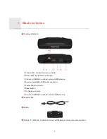
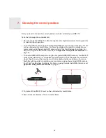
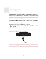
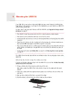
background image

TomTom LINK 510

Installation Guide

Summary of Contents for LINK 510

Page 1: ...TomTom LINK 510 Installation Guide ...

Page 2: ...status indicator CConnector SMB for optional external GSM antenna DService Update Mini USB cable connector EPower cable connector FReset button GIO Cable connector HConnector SMB for optional external GPS antenna bPower cable cHolder dFixings 2 cable ties 2 adhesive strips 2 self tapping screws and a cleaning tissue ...

Page 3: ...tion and you are warned when you are driving or cornering too fast And you can get information about how much fuel you have used What you need for the installation Before starting the installation of your TomTom LINK 510 read the safety notices and warnings carefully and make sure you have the following The TomTom WEBFLEET Contract Confirmation letter including the Activation Code All parts mentio...

Page 4: ...is that have structural or security related functions This is because you cannot be certain that they will function properly after modification Caution risk of fire Make sure you do not drill into covered wiring harnesses fuel lines or similar components Drilling into these can cause fire Caution use of this product is restricted in some areas The GSM module of the TomTom LINK 510 contains a GSM G...

Page 5: ...repair or replace parts Warning damage to the device Short circuits inside the unit can be caused by contact with water or other liquids The unit may be damaged by contact with water Use and store the unit in an area protected from water Caution risk of accidents Using a TomTom PRO navigation device while driving is distracting and can cause accidents To ensure road safety only enter information i...

Page 6: ...Update Tool from the Partner Portal under Software and Firmware You must be logged in to the Partner Portal to download the Tool The downloadable ZIP file contains the tool with the firmware update file embedded Unzip the downloaded file to your local hard disk Updating the firmware on your LINK 510 To update the firmware on your LINK 510 using the Firmware Update Tool do the following 1 Connect y...

Page 7: ... was assigned to your LINK 510 from the list and click OK At the bottom of the window you can find information about the operating system installed on the LINK device the serial number of the LINK device and which COM Port number was assigned as well as the operating system that will be installed with this update ...

Page 8: ...ext step If it is up to date disconnect your LINK 510 and continue with Activating the LINK 510 on page 11 4 Select Start to initiate the firmware update installation process The old firmware is deleted and the new firmware is installed on the device During the installation process the upper part of the window displays the installation progress ...

Page 9: ...9 5 When the firmware installation is complete click OK to confirm 6 To close the Firmware Update Tool click Exit ...

Page 10: ...ws Vista or Windows 7 you must run the tool in Windows XP compatibility mode as it is not compatible with newer versions of Microsoft Windows To run the Firmware Update Tool in XP compatibility mode do the following 1 Go to the installation folder of the Firmware Update Tool on your computer and locate the exe file 2 Right click on the exe file and select Properties 3 Select the Compatibility tab ...

Page 11: ... To activate your LINK 510 do the following 1 Install the latest version of the TomTom LINK Activation Tool You can download the Activation Tool from the Partner Portal at https business tomtom com 10001 areas reseller index xml Go to Techinical Support and select Activation and Diagnostics 2 Connect your LINK 510 to supply voltage 3 Connect your LINK 510 to your computer using the Mini USB cable ...

Page 12: ...tivation Tool asks you to enter your activation code 7 Click Activate 8 Enter the Activation Code which you can find in your WEBFLEET contract confirmation 9 Click OK The progress of the activation is shown You have now successfully activated your TomTom LINK 510 ...

Page 13: ...Connection overview 6 13 Con nec tion over view Make sure this wire is fused with max 10A ...

Page 14: ...l GPS antenna from TomTom Business Solutions For help on using the external GPS antenna read Appendix Using external antennas on page 27 To ensure GSM GPRS reception using the integrated GSM GPRS antenna the LINK 510 must not be placed on or surrounded by metal items such as the vehicle s coachwork closer than 5 cm and the top side must not be obstructed by metal items For more flexibility with re...

Page 15: ... you must connect the GND wire before you connect the PWR wire and the IGN wire as described below 1 Connect the GND wire brown to ground clamp 31 2 Connect the PWR wire red to the carry current clamp 30 The connection must be fused with max 10A If not fuse the the PWR wire with one 2A fast blow fuse 3 Connect the IGN wire black to ignition clamp 15 The connection must be fused with max 10A If not...

Page 16: ...nsured The unit must be placed on an oil free dry and clean surface when using the adhesive strips Extreme temperature changes differences can affect the adhesive property of the strips To find the right place read Safety first on page 4 and Choosing the correct position on page 14 The LINK 510 can be attached with the two adhesive strips the two tapping screws or the cable ties Attaching the hold...

Page 17: ...INK 510 Remember when the LINK 510 is in the holder it must not be obstructed by metal objects 2 Insert the two screws into the corresponding holes in the holder 3 Tighten the screws 4 Carefully place the LINK 510 in the holder until it clicks into place Attaching the holder using the cable ties You can use the two cable ties to fix the holder to your vehicle Using cable ties might have an impact ...

Page 18: ...18 5 Pull the cable ties tight so that the holder cannot move 6 Insert the LINK 510 into the holder Press gently until it clicks into place ...

Page 19: ...nd then go off every 3 seconds If the device is already activated see Activating the LINK 510 on page 11 the green LED must be on all the time If the LED does not perform accordingly see Diagnostics on page 22 GPRS reception test For this test you may need to move the vehicle to a location with a clear view of the sky to make sure that you have adequate GPS and GPRS reception For this test put the...

Page 20: ...ou are asked to start the activation process After you have started the activation process your navigation device starts searching for Bluetooth devices If your navigation device finds more than one Bluetooth device it shows a list of the available devices Continue with step 5 If your navigation device finds only one LINK 510 continue with step 6 5 Select your LINK 510 from the list The name start...

Page 21: ...ons If you have properly connected the two devices you receive a welcome message from WEBFLEET confirming the activation In future the connection is established automatically To check the connection status between the two devices tap WORK in the Main Menu on your navigation device then tap Connection status ...

Page 22: ...ics GREEN LED mode OFF Unit is in standby mode or is not connected to power Switch on ignition Check if the device is properly connected to power see Connecting to power on page 15 OFF and short ON every 3sec Ignition off Rapidly flashing No operating system and or no application available or application failed Install latest firmware application using the TomTom Business Solutions Firmware Update...

Page 23: ...nected to power see Connecting to power on page 15 Switch on ignition Move the vehicle as you may be in a GSM dead spot OFF and short ON every 3sec Not connected Correct GSM operator not avaialable Check WEBFLEET subscription for GSM network roaming support Move the vehicle as you may be in a GSM dead spot Rapidly flashing SIM not in place SIM defective Modem problem Use TomTom Business Solutions ...

Page 24: ...hen plug it into the power cable connector again Resetting your LINK to factory settings To reset the LINK 510 to factory settings press the reset button with a thin pointed object until it clicks and keep it pressed for 4 to 8 seconds The LINK 510 reboots immediately after releasing the reset button Important All information stored on the LINK 510 is deleted during a factory reset If resetting th...

Page 25: ... 30 V to be fused with max 10A Ignition to be fused with max 10A Internally fused with 2A fuse is not resettable or replaceable fuse must be replaced by TomTom Business Solutions only Temperature Operation 30 C to 70 C Storage 40 C to 80 C GSM Integrated GSM antenna and GSM module Dualband GSM 900 1800 GPS Integrated GPS antenna and GPS receiver BluetoothTM Integrated BluetoothTM class 2 for conne...

Page 26: ...ntenna female Supply voltage range 3 3 V Minimum antenna gain at 3 V 20 dB Maximum antenna gain 40 dB Maximum noise rating 1 5 dB GSM antenna connector for external GSM antenna optional accessory SMB male antenna female for use with GSM antenna from TomTom Business Solutions only ...

Page 27: ... Partner Portal Important Only use the GPS antenna from TomTom Business Solutions otherwise GPS performance may be poor or not work at all Tinted metallised windscreens or those with integrated filament heating may prevent good GPS reception In this case place the GPS antenna in the rear window or on the outside of the vehicle The magnet of the antenna remains attached to the outside of the car at...

Page 28: ...siness Solutions otherwise GSM GPRS performance may be poor or not work at all Tinted metallised windscreens or those with integrated filament heating may prevent good GSM GPRS reception In this case place the GSM GPRS antenna in the rear window or on the outside of the vehicle Install the GSM GPRS antenna in a place where it is unobstructed by metal objects The GSM GPRS antenna must be placed wit...

Page 29: ...the IO cable connector of the TomTom LINK 510 aCAN High Orange Black For FMS data retrieval bCAN Low Orange Brown For FMS data retrieval cGND Brown dIN 1 Blue Green Digital input can be connected to digital tachograph or can be used for idling reporting and logbook keeping eIN 2 Violet Digital input fOUT Green White Digital output Connecting a digital tachograph You can collect the time spent driv...

Page 30: ...d business trips This requires configuration in TomTom WEBFLEET The input IN 1 must be connected to a switch indicating the trip mode If the input IN 1 is active the logbook mode is set to Private trip If no or a low voltage applies to the input IN 1 the logbook mode is set to Business trip For detailed information on how to connect IN 1 see Wiring digital inputs on page 30 Wiring digital inputs T...

Page 31: ...ange over switch is available an electric load for example indicator light or resistor between the digital input and ground GND or between the digital input and the vehicle voltage 9 30V can offer defined levels When using inductive loads a free wheeling diode must be used in parallel with the load ...

Page 32: ...output voltage use a 12 V 24 V relay depending on the operating voltage Caution Do not switch safety relevant vehicle functions Accessing FMS data With the TomTom LINK 510 and the IO cable from TomTom Business Solutions you access the FMS interface of your vehicle Connect the CAN H and the CAN L wires of the IO cable to the CAN H and the CAN L pins of the FMS connector in your vehicle Note Make su...

Page 33: ...l product must not be disposed of as unsorted municipal waste Please dispose of this product by returning it to the point of sale or to your local municipal collection point for recycling Exposure limits This device complies with radiation exposure limits set forth for an uncontrolled environment In order to avoid the possibility of exceeding the radio frequency exposure limits human proximity to ...

Page 34: ...34 License Agreement and limited warranty apply to this product You can review it at www tomtom com legal ...

Reviews: