background image

Page 1

Specifications subject to change without notice.

©Tormach® 2021

TECHNICAL DOCUMENT

Version 0821A

INSTALLATION GUIDE

PATHPILOT OPERATOR CONSOLE ASSEMBLY

FOR 770M/770M+/770MX

Summary of Contents for 770M

Page 1: ...Page 1 Specifications subject to change without notice Tormach 2021 TECHNICAL DOCUMENT Version 0821A INSTALLATION GUIDE PATHPILOT OPERATOR CONSOLE ASSEMBLY FOR 770M 770M 770MX...

Page 2: ...ontroller Wire Kit PN 50367 1 Jog Pendant PN 50363 1 Machine Controller Note If any items are missing we can help Email support tormach com to contact Tormach Technical Support for guidance on how to...

Page 3: ...product s documentation and follow the steps in reverse order l Machine Enclosure Required If you haven t yet done so you must first install the machine s enclosure See the product s documentation for...

Page 4: ...1 Remove the Emergency Stop cable from the operator box 2 Remove the four screws that secure the operator box to the machine stand using a 3 mm hex wrench Discard the operator box 3 Put the four scre...

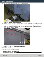
Page 5: ...ll template using a hole punch 7 Remove the drill template from the enclosure and discard it 8 Drill into the marks on the enclosure that you made in Step 6 using an electric drill and a 15 64 in 6 mm...

Page 6: ...e 4 Bottom of the mount arm level on the enclosure 11 Using the bottom of the mount arm as a template drill one hole using an electric drill and a 15 64 in drill bit 12 Put one M6 screw one washer and...

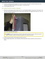
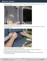
Page 7: ...y that the mount arm s screws don t interfere with the enclosure door jamb If they do loosen the screws on the door jamb and slide it toward the back of the machine Figure 6 Door jamb moved to provide...

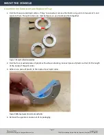
Page 8: ...assembled 2 Find the four provided pieces of plastic with adhesive backing Cut each piece of plastic so that it s the length of the inside of the split collar 3 Adhere one piece of plastic to the insi...

Page 9: ...the following image Verify that the curved edge is facing away from the controller Note Don t completely tighten the brackets to the controller You ll adjust them when you re adjusting the height of t...

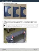
Page 10: ...to the left side of the keyboard tray with two M4 screws using a 2 5 mm hex wrench Verify that the curved edge is facing away from the keyboard tray 9 Attach one side of one split collar to the mount...

Page 11: ...embly so we suggest attaching it 16 in 41 cm from the top of the enclosure Figure 13 Split collar attached to the mount arm CAUTION Team Lift Required You must have the aid of more than one person to...

Page 12: ...wing image Figure 15 Attaching the keyboard tray to the bottom of the controller 6 Loosely attach the opposite side of the split collar to the mounting arm using a 8 mm hex wrench 7 Adjust the height...

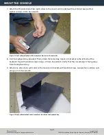
Page 13: ...ller 4 Find the provided power supply bracket Then attach it to the back of the controller with two M3 screws using a Phillips screwdriver 5 Find the provided power Ethernet emergency stop extension a...

Page 14: ...Rubber attached to the bracket on the keyboard tray 9 Put the loose ends of all cables from the controller into the corrugated tubing 10 Push the corrugated tubing into the bracket on the rear of the...

Page 15: ...Set the screws aside for later in this procedure 13 Find the provided access panel Then put the loose end of the corrugated tubing and all cords through it as shown in the following image Figure 21 L...

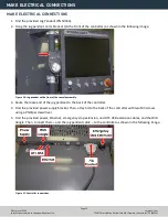
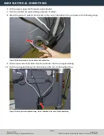
Page 16: ...ator box cable that s preinstalled on the machine Then route it through the access hole in the machine stand shown in the following image Figure 23 Preinstalled operator box cable routing 17 Connect t...

Page 17: ...need the keys For more information on operation modes refer to the Safety section of the EU machine operator s manual REASSEMBLE THE MACHINE 1 Put the right side window that you set aside in Prepare t...

Page 18: ...From the PathPilot interface in the MDI Line DRO field type ADMIN TOUCHSCREEN SENSITIVITY 1000 and press Enter You can use a value between 1 and 2047 but 1000 is generally sufficient for most shop spa...

Page 19: ...sole If it s not lit examine the power cords to the power brick If your console receives power from the Accessory Input ports on the machine look for tripped breakers inside your machine s electrical...

Page 20: ...he BIOS 3 From the Advanced tab select Display Configuration 4 Configure the display as follows l Primary IGFX Boot Display Auto l LCD Panel Type 1280x1024 LVDS l Panel Channel Dual Channel l Panel Co...

Page 21: ...n sometime cause connectors to become loose Re seating the connectors will usually fix non responsive override knobs Examine the USB connection to the control board High 1 Remove the rear panel of the...

Page 22: ...pressed remove the lower rear panel of the console and examine the screw terminals on the rear of the buttons themselves Shipping can sometime cause wire terminals to become loose Re seating the wires...

Page 23: ...r data 2 0 2 20 2019 pdenhartog SOLIDWORKS Electrical S2 5 6 3 4 S2 Reset 37342 S1 1 2 Emergency Stop 30462 X1 1 2 3 4 5 402 404 GND1 401 403 X2 39379 3 4 S3 Cycle Start 37362 3 4 S4 Feedhold 37363 PN...

Page 24: ...mm Holes Keep edge flush with top of enclosure 770M M MX PathPilot Operator Console Drill Template To download print this template go to tormach com docs Keep edge flush with right side of enclosure 1...

Reviews: