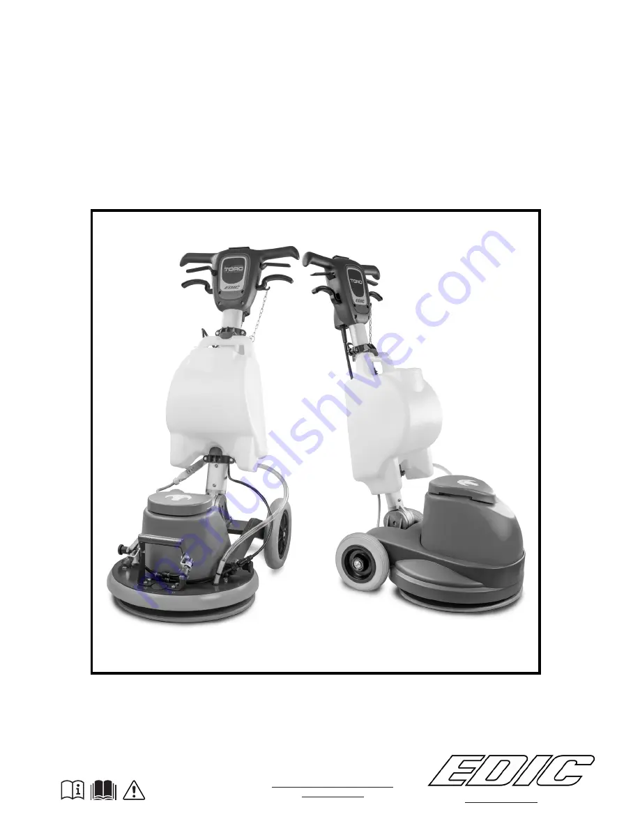
background image

TORO

OWNER’S/ OPERATOR’S 

MANUAL

FOR COMMERCIAL USE ONLY

EDIC-USA.COM

11-2-17 Revision 1

MODEL: 1725-TES & 1725-TPT

Summary of Contents for 1725-TES

Page 1: ...TORO OWNER S OPERATOR S MANUAL FOR COMMERCIAL USE ONLY EDIC USA COM 11 2 17 Revision 1 MODEL 1725 TES 1725 TPT ...

Page 2: ...ENGLISH SPANISH 3 19 ES EN ...

Page 3: ...CE 9 HOW TO TRANSPORT THE APPLIANCE 9 MAIN COMPONENTS OF THE APPLIANCE 10 MAIN COMPONENTS OF THE CONTROL HANDLEBAR 10 MAIN COMPONENTS OF THE COLUMN 10 PREPARATION OF THE APPLIANCE 11 INSERTING THE BRUSH 11 INSERTING THE SOLUTION TANK OPTIONAL 11 INSERTING THE DETERGENT SOLUTION OPTIONAL 12 WORK 13 MANEUVRABILITY OF THE APPLIANCE 14 AT THE END OF THE WORK 14 MAINTENANCE 15 RECOMMENDED MAINTENANCE O...

Page 4: ... most autonomous way It includes information concerning technical aspects safety operation appliance downtime maintenance spare parts and scrapping Operators and qualified technicians must read This manual is aimed at operators and qualified technicians responsible for appliance maintenance Operators must not perform operations that should be carried out by qualified technicians The use and Mainte...

Page 5: ...l characteristics of the appliance in particular the appliance s serial number The serial number is a very important piece of information and should always be provided together with any request for assistance or when purchasing spare parts The appliance is only suitable for use in indoor or at least covered areas ATTENTION The appliance is not suitable for use in the rain or under jets of water th...

Page 6: ...and used in a closed place The appliance must be only used by authorized trained personnel Do not use the appliance on surfaces with an inclination greater than the one shown on the serial number plate Always make sure that the work surfaces floors and ramps are able to withstand the weight of the appliance The appliance is not suitable for cleaning rough or uneven floors Do not use the appliance ...

Page 7: ...ust be stored in a closed area with a temperature between 25 C and 55 C Conditions of use room temperature between 0 C and 40 C with relative humidity between 30 and 95 The machine is not suitable for cleaning carpets or textile floors Polishing operations should only be carried out in areas where the passage of unauthorized persons is prohibited Signal the presence of work areas with suitable sig...

Page 8: ...thorized technical assistance centre If you need to replace any components request the ORIGINAL spare parts from an authorized dealer and or distributor Restore all electrical connections after any maintenance interventions Have the appliance checked by an authorized technical assistance centre every year When disposing of consumable materials observe the laws and regulations in force When after y...

Page 9: ... as reference 2 Remove the holding straps 3 Open the outer packaging ATTENTION You are advised to always wear protective gloves to avoid the risk of serious injury to your hands 4 Remove the optional accessories contained in the packing 5 Remove the appliance from the box ATTENTION During this operation check there are no people or objects near the appliance ATTENTION To remove the appliance from ...

Page 10: ...ety switch 2 Control lever main switch positioned under the grip of the handlebar 3 Handlebar tilt adjustment lever 4 Detergent distribution valve control lever 5 Brush head motor thermal circuit breaker 6 Power cable 7 Spray kit control switch MAIN COMPONENTS OF THE COLUMN The handlebar components are identified as follows 1 Upper support solution tank kit 2 Lower support solution tank kit 3 Atta...

Page 11: ...ove the fixing lugs and centering plate Fig 5 To insert the solution tank onto the handlebars proceed as follows 1 Secure the handlebar in a position at about 45 with respect to the ground Fig 1 2 Unscrewing the closing knob 1 Fig 2 position the upper brackets beyond half of the column Fig 3 if it has not already been positioned INSERTING THE SOLUTION TANK OPTIONAL 3 Put the solution tank on the c...

Page 12: ...d 4 Insert the solution tank cap 1 Fig 2 ATTENTION You are advised to always wear protective gloves to avoid the risk of serious injury to your hands ATTENTION We recommend that you vacuum at intervals the dirt loaded foam with a vacuum cleaner for liquids INSERTING THE DETERGENT SOLUTION OPTIONAL 7 Insert the solution tank tap tie chain 6 in the coupling in the tap control handle 7 Fig 8 7 8 10 7...

Page 13: ...rips on the handlebar Fig 5 8 The appliance will now start to move 9 Apply a small amount of detergent solution to the floor by pressing the lever 8 Fig 6 10 Push the appliance with the brush rotating from left to right or vice versa 11 Immediately afterwards push the appliance in the same way but in the opposite direction so that about one quarter of the working width overlaps the previous one Yo...

Page 14: ... the lever of pump control switch 8 on the control handlebar ATTENTION Pushing the lever 8 forwards starts the pump in intermittent mode Fig 7 ATTENTION Pushing the lever 8 backward starts the pump in continuous mode 2 Push the machine with the brush rotating from left to right or vice versa 3 Immediately afterwards push the machine in the same way but in the opposite direction so that about one q...

Page 15: ...handlebar to the vertical position Fig 3 When the handlebar is vertical release the uncoupling lever 4 4 Tip the appliance back Fig 4 block one of the rear wheels and shift the control column backwards 5 Loosen the fixing keys then remove the centering plate Now you can remove the brush pad holder Fig 5 6 Remove the brush from the appliance Fig 6 7 Clean the brush pad holder under running water an...

Page 16: ... 4 ATTENTION users are advised to always wear protective gloves to avoid the risk of serious injury to hands 2 Remove the detergent solution pipe 7 from the hole in the solution tank Fig 5 3 Remove the solution tank tap tie rod chain 8 in the coupling in the tap control handle 9 Fig 6 4 Turning the closing knob 10 Fig 7 shift the top brackets beyond the stops in the tank 5 Remove the solution tank...

Page 17: ...e risk of serious injury to hands 6 Clean the filter under running water if necessary remove any impurities 7 Repeat the operations in reverse order to reassemble all the parts CHECKING AND CLEANING THE DETERGENT SOLUTION DRAUGHT FILTER 1 2 3 1 4 2 5 6 3 To clean the detergent solution spray nozzle proceed as follows 1 Take the device to the dedicated maintenance area ATTENTION the place designate...

Page 18: ... extension is not connected to the appliance s power cable Check that the plug on the cable of the appliance has been inserted into the socket on the extension cable The electrical specifications of the appliance should correspond to the electrical specifications of the power supply network Make sure that the electrical specifications of the appliance correspond to the electrical specifications of...

Page 19: ...E LA MÁQUINA 25 TRANSPORTE DE LA MÁQUINA 25 COMPONENTES PRINCIPALES DE LA MÁQUINA 26 COMPONENTES PRINCIPALES DEL MANILLAR DE MANDO 26 COMPONENTES PRINCIPALES DE LA COLUMNA 26 PREPARACIÓN DE LA MÁQUINA 27 INSERCIÓN DEL CEPILLO 27 MONTAJE DEL TANQUE DE SOLUCIÓN OPCIONAL 27 LLENADO DE SOLUCIÓN DETERGENTE OPCIONAL 28 USO 29 MANIOBRABILIDAD DE LA MÁQUINA 29 AL FINALIZAR EL TRABAJO 30 MANTENIMIENTO 31 I...

Page 20: ...más adecuada autónoma y segura posible El mismo contiene información acerca de los aspectos técnicos la seguridad el funcionamiento el período de inactividad de la máquina el mantenimiento las piezas de repuesto Este manual está dirigido tanto al operador como a los técnicos cualificados encargados del mantenimiento de la máquina Los operadores no deben realizar las operaciones reservadas a los El...

Page 21: ...áquina y contiene las características generales de la máquina en particular su número de serie El número de serie es una información muy importante que se debe comunicar en cualquier pedido de asistencia o compra de repuestos La máquina es apta para ser usada exclusivamente en ambientes cerrados o cubiertos ATENCIÓN La máquina no es apta para usar bajo la lluvia o chorros de agua al incumplimiento...

Page 22: ...er utilizada exclusivamente por personal autorizado y capacitado para el uso No emplear la máquina en superficies con inclinación superior a la indicada en la placa matrícula Asegurarse siempre de que los planos de trabajo plataformas y rampas puedan soportar el peso de la máquina Lamáquinanoesaptaparalalimpiezadepavimentosirregulares o con desniveles No utilizar la máquina en pendientes En caso d...

Page 23: ... humedad ni exponerla directamente a la lluvia La temperatura de almacenamiento debe estar comprendida entre los 25 C y los 55 C y debe almacenarse sólo en ambientes cerrados Condiciones de uso temperatura ambiente comprendida entre 0 C y 40 C con humedad relativa entre 30 y 95 La máquina no es adecuada para la limpieza de moquetas o pavimentos textiles Las operaciones de pulido deben realizarse e...

Page 24: ...e de que no sean causadas por la falta de mantenimiento ordinario De lo contrario solicitar la intervención del centro de asistencia autorizado Si fuese necesario sustituir algunas piezas solicitar repuestos ORIGINALES a un concesionario y o Revendedor Autorizado Restablecer todas las conexiones eléctricas después de cualquier intervención de mantenimiento Hacer controlar lamáquina en uncentrodeas...

Page 25: ...NCIÓN Tomar como referencia las imágenes impresas en la caja 2 Retirar los bloques de sujeción 3 Abrir el embalaje exterior ATENCIÓN Se recomienda utilizar siempre guantes de protección para evitar lesiones graves en las manos 4 Retirar los accesorios opcionales contenidos en el embalaje 5 Sacar del cartón la máquina ATENCIÓN Durante esta operación asegurarse de que no haya objetos o personas cerc...

Page 26: ...lanca de mando del interruptor general situada bajo las empuñaduras del manillar 3 Palanca regulación inclinación manillar 4 Palanca de mando de la válvula de distribución del detergente 5 Disyuntor térmico de protección del motor de bancada 6 Cable de alimentación 7 Interruptor de control del kit de pulverización COMPONENTES PRINCIPALES DE LA COLUMNA Los componentes del manillar se identifican de...

Page 27: ... de las ruedas traseras y mover hacia atrás la columna de mando 4 Desenroscar y quitar los palos de fijación y la placa de centrado Fig 5 5 Insertar el disco conductor tener cuidado para centrar los pasadores de sujeción presentes en la máquina con los orificios de disco trascinatore Di seguido inserte la placa de centrado y apriete los 5 palos de fijación Fig 6 Para colocar el tanque de solución ...

Page 28: ...nque de solución 1 Fig 2 ATENCIÓN Se recomienda utilizar siempre guantes de protección para evitar lesiones graves en las manos ATENCIÓN Se aconseja aspirar en tramos la espuma cargada de suciedad con un aspirador para líquidos LLENADO DE SOLUCIÓN DETERGENTE OPCIONAL 6 Introducir el tubo de distribución del agua 4 en el orificio de la bancada 5 Fig 7 7 Enganchar la cadena tirante del grifo del tan...

Page 29: ...las empuñaduras del manillar Fig 5 8 Ahora la máquina comenzará a moverse 9 Aplicar una pequeña dosis de solución detergente sobre el pavimento presionando la palanca 8 Fig 6 10 Conducir la máquina con el cepillo giratorio de izquierda a derecha o en sentido contrario 11 Inmediatamente después conducir la máquina de la misma forma en sentido contrario pero de manera que aproximadamente un cuarto d...

Page 30: ...terruptor de mando de la bomba 8 que se encuentra en la parte superior del manillar de mando ATENCIÓN Empujando hacia delante la palanca 8 se acciona la bomba en modo intermitente Fig 7 ATENCIÓN Empujando hacia atrás la palanca 8 se acciona la bomba en modo continuo 2 Conducir la máquina con el cepillo girando de izquierda a derecha o en sentido contrario 3 Inmediatamente después conducir la máqui...

Page 31: ...la posición vertical Fig 3 Cuando el manillar alcanza la posición vertical soltar la palanca de desenganche 4 4 Inclinar hacia atrás la máquina Fig 4 bloquear una de las ruedas traseras y mover hacia atrás la columna de mando 5 Aflojar los palos de fijación a continuación retirar la placa de centraggio Ora es posible retirar el cepillo de alimentador Disco de arrastre Fig 5 6 Extraer el cepillo de...

Page 32: ...uantes de protección para evitar lesiones graves en las manos 2 Retirar el tubo solución detergente 7 del orificio presente en el tanque solución Fig 5 3 Retirar la cadena tirante del grifo del tanque solución 8 del gancho que se encuentra en la manilla de mando del grifo 9 Fig 6 4 Desenroscando la manivela de cierre 10 Fig 7 trasladar los estribos superiores más allá de los retenes presentes en e...

Page 33: ...iltro bajo un chorro de agua corriente si es necesario retirar las impurezas presentes en el mismo 7 Para el montaje repetir las operaciones indicadas para el desmontaje pero en sentido inverso CONTROL Y LIMPIEZA DEL FILTRO DE RECUPERACIÓN SOLUCIÓN DETERGENTE 1 2 3 1 4 2 5 6 3 Para limpiar la boquilla nebulizadora de la solución detergente actuar de esta manera 1 Colocar la máquina en el lugar esp...

Page 34: ...onectado al cable de alimentación de la máquina Comprobar que la clavija que se encuentra en el cable de alimentación de la máquina esté conectada a la toma del cable de alargue Las especificaciones eléctricas de la máquina corresponden con las de la red de alimentación Verificar que las especificaciones eléctricas de la máquina correspondan con las de la red de alimentación controlar los datos té...

Page 35: ...EDIC 1753 Blake Ave Los Angeles CA 90031 800 338 3342 323 660 1635 FAX 323 667 0144 Email sales edic usa com Web www edic usa com ...

Reviews: