background image

Operator’s Manual

IMPORTANT: Read this manual carefully. It contains information about your
safety and the safety of others. Also become familiar with the controls and
their proper use before you operate the product.

FORM NO. 3322–131

ProLine

62” Mower

for Mid-Size Traction Unit

Model No. 30162 – 990001 & Up

Summary of Contents for 30162

Page 1: ...efully It contains information about your safety and the safety of others Also become familiar with the controls and their proper use before you operate the product FORM NO 3322 131 ProLine 62 Mower for Mid Size Traction Unit Model No 30162 990001 Up ...

Page 2: ...No Serial No The warning system in this manual identifies potential hazards and has special safety messages that help you and others avoid personal injury even death DANGER WARNING and CAUTION are signal words used to identify the level of hazard However regardless of the hazard be extremely careful DANGER signals an extreme hazard that will cause serious injury or death if the recommended precaut...

Page 3: ... of Cut 9 Adjusting Gage Wheels 9 Adjusting the Flotation Springs 10 Tips for Mowing Grass 11 Page Maintenance 12 Service Interval Chart 12 Cutting Blades 12 Correcting Cutting Unit Mismatch 15 Setting the Front to Rear Pitch 15 Setting the Side to Side Leveling 16 Greasing the Bearings and Bushings 17 Adjust Idler Pulley 18 Replacing the Deck Belt 18 Replacing the Drive Belt 19 Replacing the Cast...

Page 4: ...Decals Safety decals and instructions are easily visible to the operator and are located near any area of potential danger Replace any decal that is damaged or lost See Traction Unit Operator s Manual for Glossary of Safety Symbols 0 ...

Page 5: ...er frame Carrier Frame Flange Screw 1 2 13 x 1 25 mm Flange Nut 1 2 13 1 6 6 Install carrier frame to traction unit Adjusting Shaft Jam Nut 1 2 13 Spacer 1 2 13 mm Spring Bushing 2 4 2 2 2 Install adjusting shafts Clevis Pin Hairpin Cotter 4 4 Install cutting unit to carrier frame Washer Cotter Pin 2 2 Install flotation springs Operator s Manual Parts Catalog 1 1 Read before operating Ordering par...

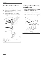
Page 6: ...ng Fig 1 1 4 2 2 5 Figure 1 1 Retaining Ring 2 Thrust Washer 4 3 Carrier Frame Mounting Tube 4 Spacer 5 Castor Wheel Fork Installing the Carrier Frame to the Traction Unit 1 Align the carrier frame holes with the mounting holes in the traction unit frame Fig 2 2 Fasten each side of the carrier frame to the traction unit with three 3 1 2 x 1 25 mm flange screws and locknuts Torque the mounting scre...

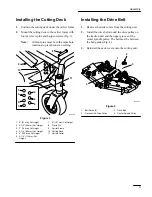
Page 7: ... Cut Height 4 3 1 2 89 mm Cut Height 5 4 102 mm Cut Height 6 4 1 2 114 mm Cut Height 7 5 127 mm Cut Height 8 Clevis Pin 9 Carrier Frame 10 Cutting Deck 11 Hairpin Cotter Installing the Drive Belt 1 Remove the deck covers from the cutting unit 2 Install the drive belt around the drive pulley on the traction unit and the upper groove of the center spindle pulley The belt must be between the belt gui...

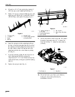
Page 8: ...rt the locknut end of the adjusting shaft into the carrier frame mounting tab Fig 6 7 To tension the belt tighten the front jam nut on each adjusting shaft until the springs are compressed to 5 12 7 cm Measure the spring compression between the spacer and the bushing Fig 6 8 Tighten the rear jam nuts Fig 6 2 1 4 3 5 M 4303 Figure 6 1 5 between the Spacer and Bushing 2 Deck Mounting Bracket 3 Front...

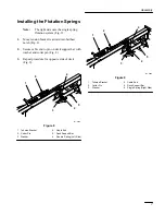
Page 9: ...ure cable end to pin on deck support bar with washer and cotter pin Fig 8 3 Repeat procedure for opposite side of deck Fig 9 1 2 4 3 M 4259 5 6 Figure 8 1 Tehsion Bracket 2 Cotter Pin 3 Washer 4 Cable End 5 Deck Support Bar 6 Double Spring Left Side 1 2 4 3 5 M 4302 2 Figure 9 1 Tehsion Bracket 2 Cotter Pin 3 Washer 4 Cable End 5 Deck Support Bar 6 Single Spring Right Side ...

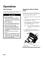
Page 10: ...r blades unless you move the power take off PTO to OFF and rotate the ignition key to OFF Also remove the key and pull the wire s off the spark plug s Engaging the Mower Blades PTO The blade control switch PTO in conjunction with the blade control bail engages and disengages power to the electric clutch and mower blades 1 Pull on the upper control bar to stop the machine Fig 10 2 To engage the bla...

Page 11: ... 5 4 102 mm Cut Height 6 4 1 2 114 mm Cut Height 7 5 127 mm Cut Height 8 Clevis Pin 9 Carrier Frame 10 Cutting Deck 11 Hairpin Cotter Adjusting Gage Wheels The gage wheels must be adjusted in the proper hole location for each height of cut position 1 After adjusting height of cut remove nut and washer while holding stud with wrench Fig 12 Note Do not remove the wheel nut and washer Fig 12 2 Select...

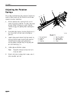
Page 12: ...tension first raise height of cut to 4 in position or block deck in the highest position 3 Adjust spring tension Relieve spring tension by moving tension bracket toward pulley and into forward notch increase spring tension by moving adjustor bracket away from pulley and into rear notch Fig 13 4 Adjust opposite flotation spring Note Opposite side does not need to be in the same notch 5 Check each s...

Page 13: ...mer mow less frequently If you cannot mow for an extended period first mow at a high cutting height then mow again two days later at a lower height setting Cutting Speed To improve cut quality use a slower ground speed Avoid Cutting Too Low If the cutting width of the mower is wider than the mower you previously used raise the cutting height to ensure that uneven turf is not cut too short Long Gra...

Page 14: ...xtra blades on hand POTENTIAL HAZARD A blade that is worn or damaged could break apart and pieces could be thrown at bystanders or at you as you use the mower WHAT CAN HAPPEN Pieces of blade that may be thrown could seriously injure or kill you or bystanders HOW TO AVOID THE HAZARD Periodically inspect the blade for wear and damage Immediately install a new blade if it is worn or damaged Before In...

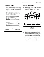
Page 15: ...slot Forming Checking for Bent Blades 1 Rotate the blades until the ends face forward and backward Fig 15 Measure from a level surface to the cutting edge of the blades Fig 16 Note this dimension m 1078 Figure 15 m 2539 Figure 16 2 Rotate the opposite ends of the blades forward Measure from a level surface to the cutting edge of the blades at the same position as in step 1 above The difference bet...

Page 16: ...p and blade from the spindle shaft Fig 17 1 3 4 m 1082 2 5 Figure 17 1 Sail Area of Blade 2 Blade 3 Anti scalp cup 4 Washer 5 Blade Bolt Sharpening the Blades 1 Use a file to sharpen the cutting edge at both ends of the blade Fig 18 Maintain the original angle The blade retains its balance if the same amount of material is removed from both cutting edges 1 m 1854 Figure 18 1 Sharpen at original an...

Page 17: ...n Make sure the clevis pins are resting on the frame cushions 4 Rotate the blades so the tips line up with one another The blade tips must be within 1 8 3 mm of each other If the blade tips are not within 1 8 3 mm of each other add shims Part No 3256 24 between the appropriate spindle housing and the bottom of the cutting unit to align the blades Setting the Front to Rear Pitch 1 Check the tire pr...

Page 18: ...tting the Side to Side Leveling 1 Check the tire pressure 2 Position the blades side to side Fig 23 Measure at A and B locations Fig 23 from a level surface to the cutting edge of blades Fig 24 3 The difference between measurements A and B should be no more than 1 4 6 mm A Front B m 1078 Figure 23 m 2550 Figure 24 4 To change the side to side leveling move the thrust washers on one castor wheel fo...

Page 19: ...e the key and disconnect the spark plug wire s from the spark plug s 2 Grease the fittings on the carrier frame mounting tubes and castor wheels Fig 25 3 Apply a few drops of oil to flotaion cable pulley bushings Fig 26 4 Grease the three spindle bearings on the deck Fig 27 m 2547 1 2 Figure 25 1 Carrier Frame Mounting Tube Grease Fitting 2 Castor Wheel Grease Fitting 1 M 4302 Figure 26 1 Pulley O...

Page 20: ...Plate 5 Idler Pulley 6 Deck Belt Replacing the Deck Belt Squealing when the belt is rotating blades slipping while cutting grass frayed belt edges burn marks and cracks are signs of a worn deck belt Replace the deck belt if any of these conditions are evident 1 Stop the engine remove the key and disconnect the spark plug wire s from the spark plug s 2 Remove all covers over pulleys 3 Remove the dr...

Page 21: ... spark plug s 2 Remove center deck covers 3 Loosen the jam nuts on each adjusting shaft to loosen the tension on the drive belt 1 2 M 4303 Figure 30 1 Jam Nuts 2 Adjusting Shaft 4 Remove the drive belt Fig 31 5 Install the new drive belt onto the traction unit drive pulley and the top groove of the center spindle pulley Fig 31 1 2 3 4 m 4257 Figure 31 1 Belt Guide 2 2 Traction Unit Drive Pulley 3 ...

Page 22: ...re 33 1 Retaining Ring 2 Thrust Washers locate as required 3 Carrier Frame Mounting Tube 4 Spacer 5 Castor Wheel Fork 4 Insert a pin punch into the mounting tube and carefully drive out the bushings Fig 34 Clean the inside of the mounting tube 5 Grease the inside and outside of the new bushings Use a hammer and flat plate to carefully drive the bushings into the mounting tube 6 Inspect the castor ...

Page 23: ...hing from the wheel hub and clean any grease and dirt from the wheel hub Fig 35 4 Inspect the roller bearing bushings spanner bushing and inside of the wheel hub for wear Replace any defective or worn parts Fig 35 5 To assemble place one 1 bushing into the wheel hub Grease the roller bearing and spanner bushing and slide them into the wheel hub Place the second bushing into the wheel hub Fig 35 6 ...

Page 24: ...ackets Fig 36 IMPORTANT The grass deflector must be spring loaded in the down position Lift the deflector up to test that it snaps to the full down position 2 4 7 1 5 6 3 Figure 36 1 Bolt 2 Deflector Mount 3 Spring 4 Cone Locknut 5 Pivot Bracket 6 Carriage Bolt 7 Locknut Storage 1 Clean any dirt and chaff from the top of the mower 2 Scrape any heavy buildup of grass and dirt from the underside of ...

Page 25: ...ot sharp 1 Sharpen blade s g g 2 Cutting blade s is are bent 2 Install new cutting blade s 3 Mower is not level 3 Level mower from side to side and front to rear 4 Underside of mower is dirty 4 Clean the underside of the mower 5 Tire pressure is incorrect 5 Adjust tire pressure 6 Blade spindle bent 6 Contact Authorized Service Dealer Blades do not rotate 1 Drive belt is worn loose or broken 1 Inst...

Page 26: ......

Page 27: ......

Page 28: ......

Reviews: