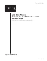
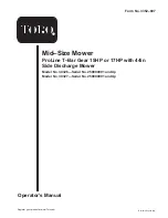
Toro 30321, Operator'S Manual
The Toro 30321 Operator's Manual is available for free download on our website. This comprehensive manual provides detailed instructions on operating and maintaining your Toro 30321. Ensure proper care and usage of your equipment by downloading the manual from 88.208.23.73:8080, your go-to source for user manuals.
Share
Download


Reviews:
No comments
Related manuals for 30321

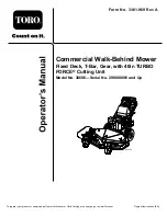
ProLine 30437
Brand: Toro Pages: 48
TC 239T
Brand: Husqvarna Pages: 120
V554
Brand: Husqvarna Pages: 44
967 672601-00
Brand: Husqvarna Pages: 128

Outlaw Stand-On
Brand: Bad Boy Pages: 44
30326
Brand: Toro Pages: 48

30332
Brand: Toro Pages: 48

30178
Brand: Toro Pages: 40
38696
Brand: Toro Pages: 44
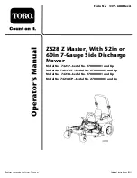
74237
Brand: Toro Pages: 60

ProLine 30259
Brand: Toro Pages: 48
78449
Brand: Toro Pages: 20

ProLine 30334
Brand: Toro Pages: 44
30528
Brand: Toro Pages: 52
78444
Brand: Toro Pages: 28

39696
Brand: Toro Pages: 44
30692
Brand: Toro Pages: 40
30986
Brand: Toro Pages: 52


