background image

Operator’s Manual

FORM NO. 3319–799

CCR

 2400 GTS

CCR

 2500 GTS

Snowthrower

Model No. 38409–8900001 & Up
Model No. 38414–8900001 & Up
Model No. 38422–8900001 & Up
Model No. 38424–8900001 & Up

Summary of Contents for 38409

Page 1: ...Operator s Manual FORM NO 3319 799 CCR 2400 GTS CCR 2500 GTS Snowthrower Model No 38409 8900001 Up Model No 38414 8900001 Up Model No 38422 8900001 Up Model No 38424 8900001 Up ...

Page 2: ...The engine exhaust from this product contains chemicals known to the State of California to cause cancer birth defects or other reproductive harm WARNING ...

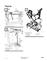
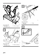
Page 3: ...inted in USA i Figures 637 1 Model and serial number decal 637 1 2 3 Unit shown on right side 1 Short spacer 2 Long spacer 3 Pushnut m 3277 1 4 5 2 3 Models 38409 38414 1 Chute ring 2 Discharge chute 3 Chute handle 4 Carriage bolt 5 Lock nut 1 2 3 ...

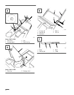
Page 4: ...k 2 Mounting bracket 3 Gear 4 Plastic bushing 1 2 636 Models 38422 38424 1 Chute ring 2 Discharge chute 2 1 4 3 m 2707 5 1 Lower handle 2 Upper handle 3 Handle bolt 4 Eyebolt 5 Lock nut 897 4 3 2 1 1 Spring 2 Cable adjuster 3 Cable 4 Z fitting 4 5 6 7 ...

Page 5: ...2 3 1 16 1 8 m 2709 4 Models 38422 38424 1 Eyebolt 2 Control bar bracket 3 Rear hole 4 Forward hole 111 1 2 3 1 Add oil to small amount of gasoline 2 Install cap and shake can to mix 3 Add remaining amount of gasoline 1 2 3 5 4 6 642 1 Key switch 2 Primer 3 Recoil start 4 Choke 5 Elec start button 6 Cord connection ELEC START MODEL 8 9 10 11 ...

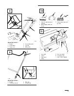
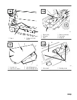
Page 6: ... 2 Chute deflector handle 3 Deflector mounting nuts 2 3 1 629 Models 38422 38424 1 Chute crank 2 Chute deflector handle 3 Deflector mounting nuts 1 2 630 3 Models 38422 38424 1 Spring cover 2 Cable adjuster 3 Z fitting 634 1 16 1 1 Scraper 12 13 14 15 ...

Page 7: ...4 631 1 Cap screw nut 2 Capscrew nut washer 3 Long self tapping screw 4 Short self tapping screws 4 2 1 6 3 5 626 1 Engine pulley 2 Idler pulley 3 Roller 4 Brake arm assembly 5 Rotor pulley 6 Belt guide 643 1 2 1 Control panel 2 Mounting screws 16 17 18 19 ...

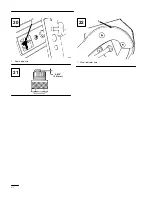
Page 8: ...vi 1 628 1 Spark plug wire 0 032 0 81 mm 110 1 1 Wear indicator hole 20 21 22 ...

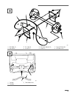
Page 9: ...4 4 5 6 7 8 680 1 Rotor blade 2 2 Rotor half 2 3 Torx screw 8 4 Locknut 13 5 Hex head capscrew 4 6 Spacer 4 7 Auger shaft assembly 8 Hex head screw 1 2 3 681 1 Thin layer 2 Thick layer 3 Wear indicator hole 23 24 ...

Page 10: ...ed Service Dealer or the factory always know the model and serial numbers of your product These numbers will help the Service Dealer or Service Representative provide exact information about your specific product You will find the model and serial number decal located in a unique place on the product Fig 1 For your convenience write the product model and serial numbers in the space below Model No ...

Page 11: ...ow children to operate the snowthrower Adults should operate the snowthrower only after reading this manual 3 Keep everyone especially children and pets away from snowthrower and area of operation 4 Inspect area thoroughly where snowthrower will be used Remove doormats sleds boards sticks wire and any other foreign objects which might be picked up and thrown by the snowthrower 5 Keep all shields a...

Page 12: ...re 20 If a foreign object is hit or snowthrower vibrates abnormally stop engine by turning key to OFF and wait for all moving parts to stop Check snowthrower immediately for possible damage an obstruction or loose parts Vibration is generally a sign of trouble Repair any damage before operating snowthrower again 21 Before adjusting cleaning repairing or inspecting the snowthrower or before unclogg...

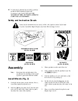
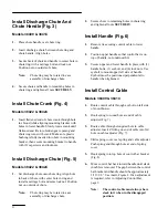
Page 13: ...wer by standing in the normal operator s position behind the handles Install Wheels Fig 2 1 Carefully turn machine onto its left side Place a wood block under the left axle end 2 Slide the short spacer and a wheel onto the right axle end The side of the wheel with six spokes must face the center of the machine 3 Slide a pushnut onto the end of the axle 4 Using a hammer strike the pushnut to seat t...

Page 14: ...f chute Note Chute ring may be rotated to ease assembly of discharge chute 2 Secure chute to remaining holes in chute ring and tighten all nuts SECURELY Install Handle Fig 6 1 Remove tie securing control cable to lower handle 2 Position upper handle so that control bar is on top of handle not underneath it 3 Secure upper and lower handle in place with 3 handle bolts 1 eyebolt and 4 lock nuts Use e...

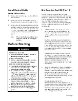
Page 15: ...oxygenated or reformulated gasoline with an octane rating of 85 or higher To ensure freshness purchase only the quantity of gasoline that can be used in 30 days Use of lead free gasoline results in fewer combustion chamber deposits and longer spark plug life Use of premium grade fuel is not necessary or recommended 1 APPROVED OIL For simplicity and best engine performance mix the contents of one 5...

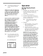
Page 16: ...panel 2 Turn key to ON and pull choke out 3 Cover hole in center of primer with thumb and push twice Additional primes may be necessary in extremely cold temperatures Note Choke and primer are usually not necessary when starting a warm engine 4 STARTING A RECOIL STARTING Hold snowthrower with one hand and pull recoil starter vigorously with other hand B ELECTRIC STARTING Connect extension cord to ...

Page 17: ...owthrower self propels However depth and height of snow affects forward speed Always overlap each swath and discharge downwind whenever possible 3 Keep the area to be cleared free of stones toys or other foreign objects which may be picked up and thrown by the rotor blades Such items could be covered by snowfall and therefore unnoticed until struck by the rotor blades Always be sure to keep childr...

Page 18: ...s gap Reinstall spring cover over cable adjuster and spring Rehook spring into top hole of control bar bracket Fig 8 B Models 38422 38424 Unhook upper cable end from hole in control bar bracket Fig 9 Slide spring cover up cable to expose cable adjuster Fig 14 Unhook Z fitting from cable adjuster and reposition Z fitting in a higher or lower hole on adjuster to obtain proper gap of 1 16 1 8 between...

Page 19: ...ller as shown 5 Reinstall belt cover Tighten fasteners securely but DO NOT OVERTIGHTEN Replacing Spark Plug Before each snow season check the spark plug If electrodes in center of plug are dark or have deteriorated install a new plug Use an NGK BPMR4A spark plug and set gap at 032 81 mm 1 REMOVE CONTROL PANEL Fig 19 Remove 3 capscrews securing control panel to housing Remove ignition key and lift ...

Page 20: ...ecurely Storage 1 FUEL SYSTEM PREPARATION Note A fuel stabilizer conditioner is most effective when mixed with fresh gasoline Add Toro Stabilizer Conditioner to the fuel tank one ounce per gallon of fuel Run engine for five minutes to distribute conditioned fuel through fuel system Stop engine allow it to cool and drain fuel tank or run engine until it stops Restart the engine again and run it unt...

Page 21: ...t Must You Do To Keep The Warranty In Effect You must maintain your TORO GTSĆ5 Engine by following the maintenance schedule detailed in the operator s manual at your expense You must record this work in the maintenance chart provided in your owner s manual and keep your proof of purchase How Do You Get Service If the starting performance of your TORO GTSĆ5 Engine should diminish to the point where...

Page 22: ...heck the operator s manual to ensure you are using the correct starting procedures This can save an unnecessary visit to a Service Dealer All warranty repairs reimbursable under this warranty must be performed by an Authorized TORO Service Dealer using Toro approved replacement parts The above remedy through repair by an Authorized TORO Service Dealer is the purchaser s sole remedy How Does State ...

Page 23: ...wing maintenance after every 25 operating hours more often in dusty and dirty conditions Follow the procedures in this Operator s Manual and record information on this chart Date Hours Used Change Oil Air Cleaner Service Lubricate Wheels Check Spark Plug Storage Doesn t Apply to 2 Cycle Mowers only Mowers only ...

Page 24: ...e part will be repaired or replaced by Toro free of charge Owner s Warranty Responsibilities As the engine owner you are responsible for the performance of the required maintenance listed in your owner s manual Toro recommends that you retain all receipts covering maintenance on your equipment but Toro cannot deny warranty solely for the lack of receipts or for your failure to ensure the performan...

Page 25: ...priming system Fuel pump Air fuel ratio feed back system Carburetor and internal parts Fuel injection system Air Induction System Air cleaner Reed intake system Intake manifold Controlled hot air intake system Ignition System Spark plug s Ignition coils and electronics Advance retard mechanisms Catalytic Converter Thermal Reactor System Catalytic converter Thermal reactor Exhaust manifold Air Inje...

Page 26: ...cidental or consequential damages in connection with the use of the TORO Products covered by this warranty except for damages to other engine components caused by the failure of a warranted part still under warranty Some states do not allow exclusions of incidental or consequential damages so the above exclusion may not apply to you This warranty gives you specific legal rights and you may also ha...

Page 27: ......

Page 28: ...Does Your State Law Relate To This Warranty There is no other express warranty except for special emission system coverage on some products and the TORO Starting Guarantee on GTS Engines This express warranty does not cover Cost of regular maintenance service or parts such as filters fuel lubricants tuneĆup parts blade sharpening brake and clutch adjustments Any product or part which has been alte...

Reviews: