background image

EO2-38080C


Serial Interface Board 


シリアルインターフェースボード


B-EX700-RS-QM-R Installation Manual 


Thank you for purchasing TOSHIBA B-EX700-RS-QM-R Serial Interface Board. 

The B-EX700-RS-QM-R is exclusively for the B-EX4T and B-EX6T series.  

このたびは、シリアルインターフェースボード

 B-EX700-RS-QM-R

をお買い上げ頂き、誠にありがとうございます。


本キットは

B-EX4T

シリーズおよび

B-EX6T

シリーズ用インターフェースボードです。


NOTE:
  This module cannot be used together with the B-EX700-WLAN*-QM-R wireless LAN board.  


このモジュールは、無線 LAN ボード

B-EX700-WLAN*-QM-R

と同時に使用することはできません。 


WARNING!

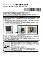
1. Follow all manual instructions.  Failure to do so could create safety hazards such as fire or 

electrocution.  


Manual instructions must be followed when installing option kits or adding cables to avoid system 
failures and to insure proper performance and operation.  


Failure to follow manual instructions or any unauthorized modifications, substitution or change to 
this product will void the limited product warranty. 

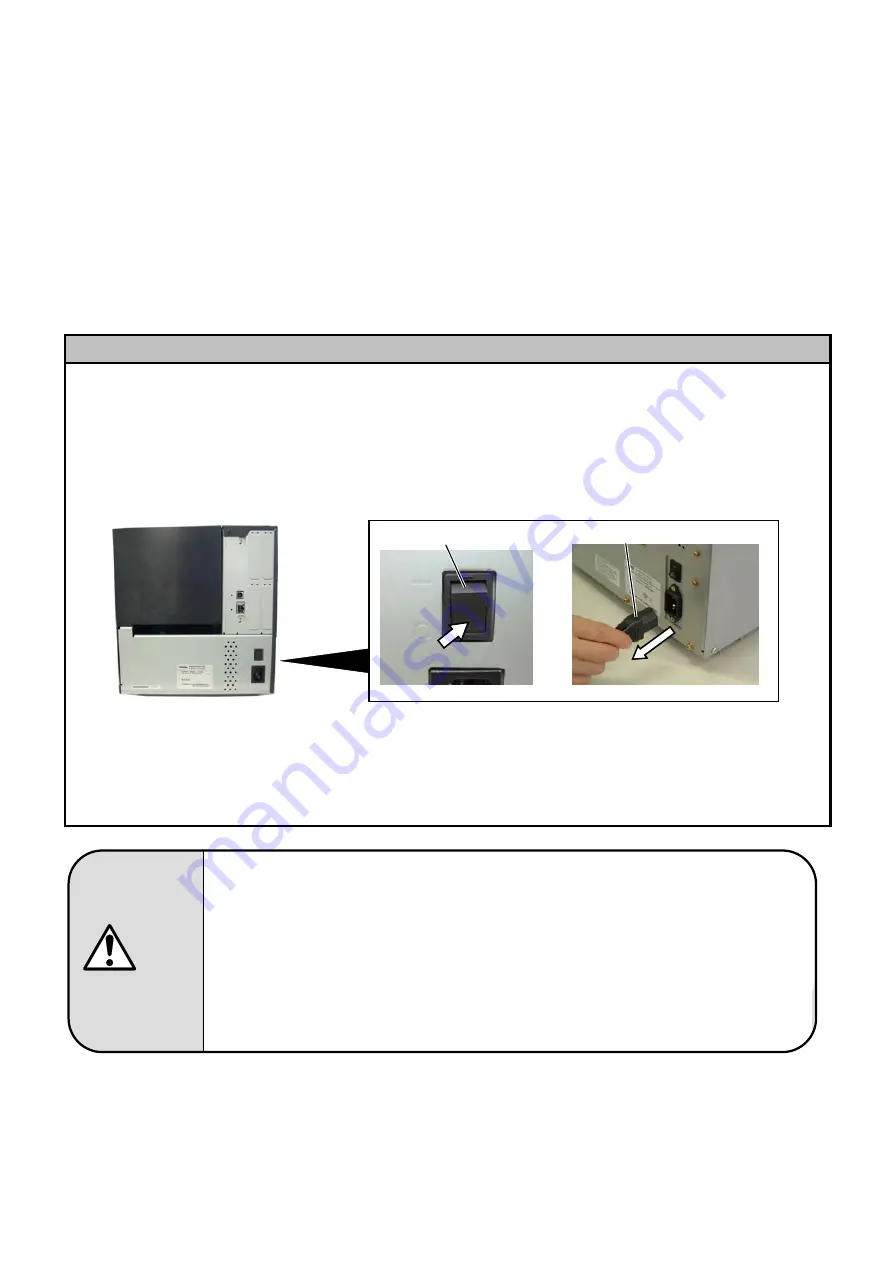
2.  Turn the power off and disconnect the power cord before installing this optional kit.  


3.  Be careful not to pinch your fingers or hands with the covers.  
4.  The print head and stepping motor becomes very hot immediately after printing.  Do not touch the print 

head, stepping motor and around it right after printing, or you may get burned.  

5.  When opening the top cover, it must be fully opened.  Failure to do this may cause the top cover to close 

under its own weight, resulting in an injury.  


Power Switch

Power Cord


! 0 0 T S C C 0 2 1 9 6 0 2 !  

1.  組み込む前にプリンタの電源スイッチを OFF にし、電源プラグをコンセントから抜くこと 
 

電源がONの状態で組み込むと、火災・感電・けがの恐れがあります。また、プリンタ内
部の電気回路保護の為、プリンタの電源 OFF 後1分以上経過してからケーブルの着
脱を行うこと。 

2.  カバーで指や手を挟まないよう注意すること 
3.  トップカバーは左側へ倒すように全開にすること 

中途半端な状態にしておくと勝手に閉まり、けがの原因となることがあります。 

4.  印字直後は、印字ヘッド、ステッピングモーターおよびその周辺部に手を触れないこと 


やけどの原因となることがあります。 

警告


Summary of Contents for B-EX700-RS-QM-R

Page 1: ...Failure to follow manual instructions or any unauthorized modifications substitution or change to this product will void the limited product warranty 2 Turn the power off and disconnect the power cord before installing this optional kit 3 Be careful not to pinch your fingers or hands with the covers 4 The print head and stepping motor becomes very hot immediately after printing Do not touch the pr...

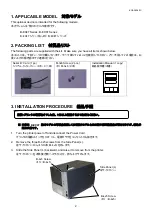
Page 2: ...Card 1 pc シリアルインターフェースボード 1枚 M 3x6 Screw 2 pcs ネジ M 3x6 2本 Installation Manual 1 copy 組込説明書 本書 3 INSTALLATION PROCEDURE 組込手順 本書は B EX4T 海外モデルの写真を使用しており国内モデルとは外観や標準装備品が異なりますが 組込手 順は共通です 1 Turn the printer power off and disconnect the Power Cord プリンタの電源スイッチを OFF にし 電源プラグをコンセントから抜きます 2 Remove the three B 4x5 screws from the Side Panel L 左サイドカバーからネジ3本 B 4x5 を外します 3 Slide the Side Panel L backward and ...

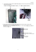
Page 3: ...し プリンタ後部から目隠し板を引き抜きます 5 Fit the Serial Connector of the Serial Interface Board into the slot from the inside and secure it with the two M 3x6 screws from the outside as shown below 目隠し板を外したスロットにプリンタの内側からパラレルインターフェースボードのコネクタを差し込み 外側からネ ジ2本 M 3x6 で固定します Serial Interface Connector シリアルインターフェースボードのコネ クタ M 3x6 Screw ネジ M 3x6 M 3x6 Screw ネジ M 3x6 Blind Plate 目隠し板 Tab ツメ Tab ツメ ...

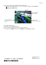
Page 4: ... EX6T series J8 connector for B EX4T series 7 Re install the Side Panel L 左サイドカバーをプリンタに取り付けます 8 Refer to the Service Manual for the interface parameter settings サービスマニュアルを参照してインターフェースに関連するパラメータ設定を行ってください J6 J8 Main PC Board メイン PC 板 Interface Cable インターフェースケーブル Serial Interface Board シリアルインターフェース ボード PRINTED IN INDONESIA EO2 38080C 東芝テック株式会社 2017 ...

Reviews: