background image

Summary of Contents for V-S46

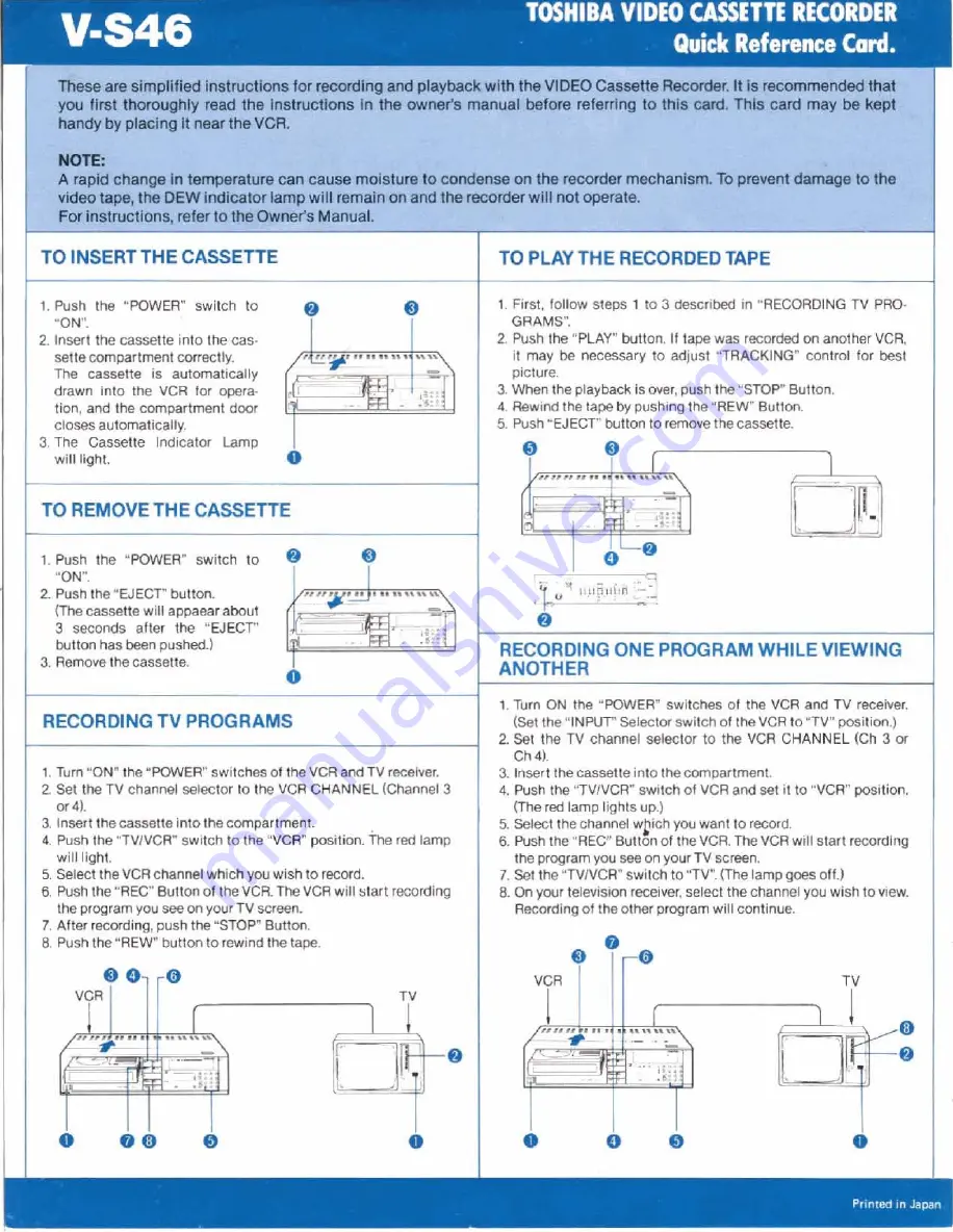
Page 1: ...onhasbeenpushed 3 Removethecassette RECORDINGTV PROGRAMS 1 Turn ON the POWER swltchesof theVCRandTV receiver 2 Set the TV channel selector to the VCR CHANNEL Channel3 M 4 3 InsertthecassetteIntothecompartmml 4 Pushthe TVIVCR switchto the VCR position h e red lamp will light 5 SelecttheVCRchannelwhichyouwishtorecord 6 PushIhe REC Buttonof theVCR TheVCRwill start recording the programyou seeonyourTV...

Page 2: ... minutedigitwill beflashlng 8 Pressthe SET buttonuntil the tens minutedigit reads 1 9 Pressthe ENTER button Then the minutedigit will beflashing 10 Pressthe SET buttonuntilthe minutedlgit reads 5 11 Pressthe ENTER button Then OFF displaywill appearwith PMnand 8 flashing belngready tor the OFF tlme setting 12 Set the OFF tlme to PM 9 OO in the same manneras in the above 6 through 111 Then CH will n...

Page 3: ... Head System 3 20 Function Wireless Remote Control 4 New FashionableDesign 5 Electronic Counter Elapsed Timer Display 6 CableT V Facility 7 Clean Editing System 8 Six Motors 7 SHOULD YOUR UNIT REQUIRESERVICE PLEASEREFER TO TOSHIBA SERVICEPROCEDURE ON BACK COVER ...

Page 4: ...ur video cassette recorder Model No Serial No Retain the information for future reference CAUTION TO REDUCE THE RlSK OF ELECTRIC SHOCK 00 NOT REMOVE CWER OR BACK NO USER SERVICEABE PARTS INSIDE REFER SERVICING TO QUAUFIED SERVICE PERSONNEL The lightning flash with arrowhead symbol within A an equilateral triangle is intended to alert the user to the presence of uninsulated dangerous voltage within...

Page 5: ...NTROLS 9 20 AUDIO DUBBING 2 1 EDITING RECORDING 21 RECORDING ONE PROGRAM WHILE VIEWING ANOTHER 22 VCR TO VCR DUBBING 22 USING ACAMERA WITH THE VCR 23 PROGRAMMABLE TIMER 24 27 CONFlRMlNG THAT PROGRAM S ARE PRESET 27 TO CANCEL PREVIOUSLY TIMED PROGRAM S 27 USING THE PICTURE SEARCH CUE AND REVIEW FEATURES 28 USING THE AUTO FINDHFEATURE 29 USING THE MEMORY FEATURE 29 USING THE TAPE COUNTERIPLAY TIME F...

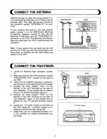
Page 6: ... the VCR ANTENNAS VCR 1 Locate the Antenna Cable accessory number 1 2 Slide one end onto the VCR connector marked TELEVISION OUT ocated on the back of the VCR 3 Locate the U V Splitter accessory number 2 and connect it to the opposite end of the cable 4 Connect the wires marked UHF on the Splitter to the UHF terminals on the back of your television If you already have an adaptor on your TV antenna...

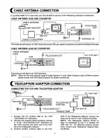
Page 7: ...Cable Company usesa different system pleaseconsult with the Cable Company for proper connections CONNECTING THE VCR AND TELECAPTlON ADAPTOR TO VHF ANT TELECAPTION TELEVISION OUT 1 Connect the TV antenna lead to the VC R OUT on the Telecaption Adaptor Connect the ANTENNA IN Connector other end to the TV VHF Antenna Terminal 2 Connect the Antenna Cable accessory number NOTE The Telecaption Adaptor s...

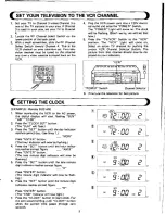
Page 8: ...uld now be dis played on your television 1 VCR I I POW R Switch Channel elector1 6 Fine tune the television for best picture SETTING THE CLOCK EXAMPLE Monday 9 00AM 1 When connecting the VCR to the AC power the digital display will start flashing SUN AM 12 00 CH 2 Press the CLOCK SET bu tton The SUN will flash 3 Press the SET button until the day indicator reaches correct day See Note 1 nn 4 4 u 9...

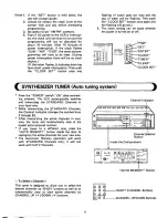
Page 9: ...setting can be made whether the power is turned on or off OPEN Press the POWER switch ON after connect ing antenna The VCR automatically searches and memorizes the STANDARD Channels in your local area while memorizing the STANDARD Channels the Channel lndicator changes the number from 2 through 83 After memorizing the active channels in your area the tuner will automatically stop at the lowest act...

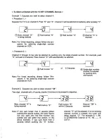
Page 10: ... seconds Single digit number channel is received by pushing only Note For timed recording always follow Pro cedure 1 for selecting single digit number channelson VCR one button Example2 Supposeyou wish to select channel 38 Two digit channels will of course require 2 buttons to be pressed in sequence Now channel 4 is Push button 3 Push button 8 Channel 38 is being received within 2 Seconds received...

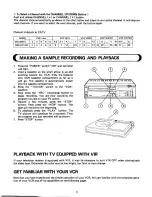
Page 11: ...recording You are now recording the program you see on your TV screen 5 Record a few minutes press the STOP button Then press the REW button The tape will rewind to the beginning 6 To playback press the PLAY button The TV picture will continue for a moment Then the program you just recordedwill be shown P BAND CHANNEL P INDICATOR 7 Press STOP button PLAYBACK WlTH TV EQUIPPED WlTH VIR VHF HIGH If y...

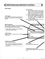
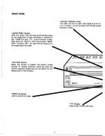
Page 12: ...h is automatically set to cancelled the VCR position Note The red lamp will light when the TVIVCR switch is in VCR positi Cassette Compartment When a cassette is inserted in this compartment the cassette will automatically be ready for opera tion The cassette indicator lamp will light Avoid inserting anything into the cassette compartmentexcept a cassette EJECT Button Used to remove the cassette f...

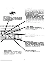
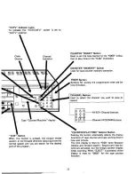
Page 13: ...ack a recorded tape with other VCR The STILL picture may be slightly distorted when the tape is recorded in p l l speed 2 TIMES Indicator To indicate double speed playback operation Two times speed can be controlled only from the Remote Control Seepage 32 Cassette lndicator Lamp When a cassette is correctly set in the cassette com partment and ready for operation this cassette indicator lamp will ...

Page 14: ...ng of each recording is reached in the REWind and F F Fast Forward modes With both the AUTO FIND and counter MEM ORY switches OFF the tape will be rewound to the beginning of the tape REVIEW Button When this button is pressed the picture moves quickly in reverse direction about 8 times the normal playback speed and you can search for the desired part of the program AFM STEREO I 117Cl REWWindButton...

Page 15: ...LAYTIME Selector Button CUE Button Pushing the button alternately selects the display When this button is pressed the picture moves functions of tape counter and tape running time in quickly in the forward direction about8times the hour and minute normal speed and you can search for the desired The time display is reset to 0 00 when Betascan part of the program reverse and forward search Rewind an...

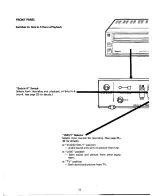
Page 16: ...fi Switch INPUT Selector Selects input sources for recording See page 35 36 for details at AUDIO ONLY position Audio sound only with no picture from line at LINE position Both sound and picture from other equip ment at TV position Both sound and picture from TV ...

Page 17: ...Channel Selector Selects audio outputs of a recorded by Beta hi fi system See page 33 for details at R position Selects right channel of helically scanned Beta hi fi stereo sound at L position Selects left channel of helically scanned Beta hi fi stereo sound at RIL position Selects both RIL channel of helically scanned Beta hi fi stereo sound The above three positions have no bearing for playback ...

Page 18: ...k Allow a second or two for the new settings of this control to take effect Always return this control to its central position after use This posi tion is indicated by a definite notch which can be felt as the control is turned When playing back tapes recorded on this VCR this control should be in the center position MI C a c c Used for connecting a microphone for dubbing sound onto a tape or for ...

Page 19: ...1 9Omin 180min 270min 300min P 11 AUTO MEMORY Switch In case u f l switch has been pressed ON before the antenna connection simply press the button Then memorizing the active channels in your area will be automatically achieved with a rapid successive indication of the channel number display t t is not necessary to operate this button when the POWER switch is pressed after the antenna connection i...

Page 20: ...itched This receptacle supplies AC 120V 60Hz max 400 watts Power is supplied regardless of the power switch mode on or off Power Cord Connect this cord into the AC outlet AC 120V VCR VHF OUTput Channel lector Switch Set this Switch to a locally inactive channel Ch 3 or Ch 4 If channel 3 is in use in your area set this switch to the Channel 4 position When playing back a recorded tape the TV set mu...

Page 21: ...available at these jacks It can be connected to an external audio amplifier The level at these jacks is 0 25 Vrms TELEVISION OUT Connect this terminal to your television ANTEN NA terminals using the accessoriesprovided AMERA REMOTE Jack You can start and stop recording by a trigger switch on the camera when you connect the trigger output of the camera to this jack Note to CATV system installer Thi...

Page 22: ...CHANNEL DOWN r Button TV VCR Button CHANNEL UP A Button AUDIO DUB Button REC Button REW Button FF Button REV EW Button LUE Button YC 36 PLAY Button PAUSE STI LL Button TO8HlBA P These buttons function same as from the VCR ...

Page 23: ...NG UP A Button for SLOW operation AUDIOWB SPEED DOWN 7 button for PICTURE SEARCH and SLOW operation SPEED UP A button for PICTURE SEARCH and SLOW operation The function of these buttons is available only from this unit see Pages 31 and 32 for details ...

Page 24: ...on again to 5 Set the INPUT selector switch to LINE start the dubbing position 11 Pressthe STOP button to stop the dubbing Note Sound is recorded on the conventional horizontal Monaural Track See page 33 EDITING RECORDING 1 Push PLAY button and watch the program 4 When you want to begin recording push the until the exact point is reached where you PAUSE STILLW button again The new want the new rec...

Page 25: ... start recording the program you see on your TV screen 7 Set the TV VCRH switch to TV The lamp goes off 8 On your television receiver select the channel you wish to view Recording of the other program will continue Note Any connectionto VIDEO IN jack should be disconnected Video Equipment amera or another VCR VCR TO VCR DUBBING If you wish to exchange or copy some of your 1 Connect VIDEO OUT AUDlO...

Page 26: ...ur television set to the VCR channel 3 or 4 6 Insert acassette tape into the cassette compart ment 7 Press the TV VCRW switch to the VCR position Your television set will act as a monitor of the picture and sound from the camera and micro phone The microphone is built into the camera 8 Push the REC button to begin recording The REMOTE PAUSE switch on the camera can be used to stop recording betwee...

Page 27: ...flashes it indicates there has been short power interruption Then push the CLOCK SET switch in the VCR ON mode and flashing will stop DESCRIPTION OF DISPLAY AND SETTING BUTTONS The clock display device is used also for program ming and its total display function is as illustrated below E E g E E E ez eE 5SBE E Timer Display 1st 2nd SUN MON TUE WED THU FRI SAT CH Channel Indicator PGM Used to call ...

Page 28: ...gramming The following example illustrate the various ways the timer may be programmed EXAMPLE I Program No 1 Channel 6 on Friday this 1st week from 8 15 pm to 9 00pm After turning the VCR ON by pressing the POWER switch Press the PGM program button Program number 1 will be flashing For other pro gram numbers press tile SET uutton until you reach the desired number Press the ENTER button Then 1st ...

Page 29: ...tant Notes on page 27 E X A M P L E lI Program No 2 Channel 24 on Wednesday next 12ndl week from 6 00am to 6 30 1 am 1 Follow the same steps 1 and 2 a s in the above 3 Follow the same steps 3 through 14 as in the EXAMPLE I above EXAMPLE I 2 Press the SET button until 2nd is flashing 1 EXAMPLE III Program No 3 Channel 8 every day of the week from 11 00prn to 11 15 pm 1 Follow the same steps 1 and 2...

Page 30: ...me day everyweek programswill stay memorized unless cleared by the CLEAR button Other programs will go off after they are executed 7 When the TIMER button is pressed for un attended recording the program display will indicate the program which is to be executed earliest in time for about 5 seconds and then automatically switched back to the clock dis play From Till AM 12 00 PM 115 9 2nd weekJ I 1 ...

Page 31: ...hen operated a t VCR s control panels 2 The speed is 5 20 times adjustable when operated at the Remote Control Unit 4 During picture search operation a few noise bars will appear on the playback picture 5 During picture search operation if the picture flows vertically on the TV screen adjust the V HOLDKnobontheTVset 6 During picture search operation the speed will be increasedupto the same speed a...

Page 32: ... function rn marma c m DEW R A Y T M E 0 0 0 USING THE MEMORY FEATURE The memory feature allows you to return to a specific spot on the tape after recording or play back The memory works together with the count er and is designedto stop when the counter reaches 0000 during rewind REW When the MEMO RY button is pressed M is indicated on the right side of the counter display This feature is especial...

Page 33: ...TIME button to automatically function as a four digit tape shift the display to count the recording play COUNTER back time in hoursand minutes 2 Push the RESET button to reset the display 2 Push the RESET button to reset the display to 0000 to 0 00 I BUT0 FIND n Min T Y C a m m DEW PLAYTIME TIMEITAPE COUNTER CHART The following chart indicates an approximate relation between Record Playback time a...

Page 34: ...fully install batter ies to match the polarity diagrams REMOTE CONTROL OPERATION RANGE The Remote Control must have Line of Sight to the receiver on the front of the VCR It must be within an angle of 30 either side of center The maximum operating distance is 23 feet FRONT END I Point the Front End of the Remote Control at the VCR REVlEW SLOW TRACKING DOWNv TRACKING SPEED DOWN r UPA ...

Page 35: ... visual noise occurs during slow motion adjust the tracking button A or r 5 Push PLAY button to return to normal play But in rare case there hasbeenremainednoisewhen playing back a recordedtape with other VCR Notes 1 The SLOW mode will cease automatically after a lapse of approximately 5 minutes and the VCR will return to normal play back mode 2 During FORWARD SLOW opera tion the sound will be mut...

Page 36: ... stereo sound can be enjoyed for a s long as 5 hours continuous ly Conventional horizontal Monaural Track TAPE Beta hi fi Track Specification Comparison Switches for Beta hi fi See Pages 13 14 35 and 36 for details MFT TRACKING AUDIODUB Conventional pll 2 0cm sec PIll 1 33cm sec P II 50Hz 8KHz Plll 50Hz 7KHz p p Items Relative tape speed Audio Track Frequency Range Dynamic Range Distortion Crossta...

Page 37: ...ECORDlNGlPLAYBACKCONNECTIONS Example I COLOR MONITOR VIDEO AUDIO OUTPUT A AUDIO VIDEO L R MONITOR TV IN A AUDIO VIDEO v 9 VIDEO MONITOR CABLE v 1 AUDIO MONITOR CABLE 1 RF Cable AUDIO OUT L STEREO SET 1 COLOR MONITOR ...

Page 38: ...LY nD OFF DE 1 M I X Records both sound and pic Records sound from audio Records sound only from ture from TV equipment and picture from audio equipment TV with No picture Note When the sound noise will occur in play back adjust the tracking control of the VCR to reducethe noise Notes 1 When the Beta hi fi switch is in ON position the sound is recorded on both Beta hi fi tracks and the conven tion...

Page 39: ...osition 2 at R position Sound Tracks 3 at L position BJ With Beta hi fi MIX switch set to MIX position m Sound Tracks Monauralsound will not be played back 1 at R L position Monaural sound w i l l be played 2 at R position R R back simultaneously 3 a t L position L L 3 Now ready for playback Notes 1 Regardless of the Beta hi fi switch position the sound of the tape recorded on the conventional mon...

Page 40: ... cassette Placethe cassette in its protective sleeve to protect it from dust If you wish to save a recording and preventacci It is not necessary to rewind the tape before dental erasure remove the erase prevention tab removing the cassette but if you do it will be from the cassette This will prevent recording on ready to play or record the next time you use it the cassette Be sure the VCR Channel ...

Page 41: ... the recording mode even when the REC light is not on DEW indicator lamp is on Press the TV VCRH switch to VCR posi tion Set the television to the same channel selected on the RF Channel Selector Switch on bottom rear of VCR Channel 3 or 4 Remove connector from the VIDEO IN jack if it has been connected Adjust Tuning Controls on VCR and televi sion to obtain the best picture When recording off the...

Page 42: ...e tuning knob on television set to obtain the best picture Adjust TRACK1NG control Wait until DEW Light goes out CLOCK AND DEW LIGHT C Symptom I I Check Point Correction Time display is flashing VCR does not start at preset record start time DEW Light remains ON PAUSE STI LL Light remains ON Reset time according to instructions Power has been interrupted Set up recording start and up time accordin...

Page 43: ...75ahm unbalanced sync negative VIDEO LlNE OUT 1V p p Phono typeconnector 75ahm unbalanced sync negative AUDIO LINE IN Phono type50kahms 10dB MIC IN Oin jack more than 600ahms 70dB AUDIO LlNE OUT Phono type less than 10k ohms 7 dB unbalanced 10dB unbalanced Beta hi fi With 3 5 min L 500 Within 3 5 min L 500 16 8 16 x 4 2 16 x 15 6 16 inches W H D 26 9 Ibs ...

Page 44: ...enclose your receipt to a Toshiba Service Center TNHAWAII Toshiba America Inc 19500 South VermontAve 2900 MacArthur Blvd Toshiba Hawaii Inc Sewice Center Torrance Cal 90502 Northbrook 111 60062 Service Department 82 Totowe Road Phone Number Phone Number 327 Kamakee Street Wayne New Jersey 07470 213 538 9960 312 564 1200 Honolulu Hawaii 96814 Phone Number 213 770 3300 Phone Number 201 6288000 808 5...

Reviews: