background image

W7 Adjustable Speed Drive Installation 

and Operation Manual

Document Number: 57442-000

Date: June, 2005

Summary of Contents for W7 Series

Page 1: ...W7 Adjustable Speed Drive Installation and Operation Manual Document Number 57442 000 Date June 2005 ...

Page 2: ... and quick changes when required To maximize the abilities of your new W7 ASD a working familiarity with this manual will be required This manual has been prepared for the W7 ASD installer operator and maintenance personnel The W7 ASD is truly Reliability in motion Important Notice The instructions contained in this manual are not intended to cover all details or variations in equipment types nor ...

Page 3: ...e used Read the manual completely before installing operating performing maintenance or disposing of this equipment This manual and the accompanying drawings should be considered a permanent part of the equipment and should be readily available for reference and review Dimensions shown in the manual are in metric and or the English equivalent Because of our commitment to continuous improvement Tos...

Page 4: ...IBA INTERNATIONAL CORPORATION W7 Adjustable Speed Drive Please complete the Warranty Card supplied with the ASD and return it to Toshiba by prepaid mail This will activate the 12 month warranty from the date of installation but shall not exceed 18 months from the shipping date Complete the following information and retain for your records Model Number ______________________________________________...

Page 5: ...ion 7 System Integration Precautions 8 Personnel Protection 8 System Setup Requirements 9 Operational and Maintenance Precautions 10 Service Life Information 10 Motor Characteristics 11 Pulse Width Modulation Operation 11 Overload Protection Adjustment 11 Power Factor Correction 11 Light Load Conditions 11 Load produced Negative Torque 11 Motor Braking 12 ASD Characteristics 12 Over current Protec...

Page 6: ...eration 30 Operation Local 30 Default Setting Changes 30 System Configuration and Menu Options 32 Root Menus 32 Frequency Command Screen 32 Monitor Screen 33 Program Screen 34 Program Menu Navigation 35 W7 ASD Direct Access Communication Numbers 46 W7 ASD Parameter Descriptions 51 Enclosure Dimensions and Conduit Plate Information 143 Enclosure Dimensions Weight 144 Alarms Trips and Troubleshootin...

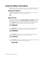
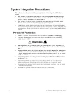
Page 7: ...sed in this manual they will be followed by important safety information that must be carefully adhered to The word DANGER preceded by the safety alert symbol indicates that an imminently hazardous situation exists that if not avoided will result in death or serious injury to personnel The word WARNING preceded by the safety alert symbol indicates that a potentially hazardous situation exists that...

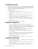
Page 8: ...les of labels that may be found on the equipment CAUTION Excessive Loading of Operating Shaft Can Prevent Contactor From Closing Properly Resulting In Major Damage Do Not Use Contactor Shaft To Drive Accessories Such As Mechanical Interlocks Which Require More Than 5 Kgf cm Of Torque To Operate DANGER DO NOT OPEN THIS DOOR WHILE THE UNIT IS RUNNING THIS DOOR IS INTERLOCKED WITH ASD OPERATION HAZAR...

Page 9: ...ng damage Carefully unpack the equipment and check for parts that may have been damaged during shipping missing parts or concealed damage If any discrepancies are discovered it should be noted with the carrier prior to accepting the shipment if possible File a claim with the carrier if necessary and immediately notify your Toshiba sales representative DO NOT install or energize equipment that has ...

Page 10: ...C Do not store the unit in places that are exposed to outside weather conditions i e wind rain snow etc Store in an upright position Disposal Never dispose of electrical components via incineration Contact your state environmental agency for details on disposal of electrical components and packaging in your area ...

Page 11: ...ctrical noise are present The installation location shall not be exposed to direct sunlight Allow proper clearance spaces for installation Do not obstruct the ventilation openings Refer to the section titled Installation and Connections on pg 13 for further information on ventilation requirements The ambient operating temperature range of the W7 ASD is 14 to 104 F 10 to 40 C See the section titled...

Page 12: ...onnect the output terminals to a motor of the correct voltage and type for the application refer to 2005 NEC Article 300 Wiring Methods and Article 310 Conductors For General Wiring Size the branch circuit conductors in accordance with 2005 NEC Table 310 16 Adhere to the recommended conductor sizes listed in the section titled Cable Terminal Specifications on pg 154 If multiple conductors are used...

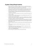
Page 13: ...tor and use V f control External dynamic braking resistors must be thermally protected It is the responsibility of the person installing the ASD or the electrical maintenance personnel to setup the Emergency Off braking system of the ASD The function of the Emergency Off braking function is to remove output power from the drive in the event of an emergency A supplemental braking system may also be...

Page 14: ... performed by Qualified Personnel Only A thorough understanding of the ASD will be required before the installation operation or maintenance of the ASD Rotating machinery and live conductors can be hazardous and shall not come into contact with humans Personnel should be protected from all rotating machinery and electrical hazards at all times Insulators machine guards and electrical safeguards ma...

Page 15: ...se intermittent system operation i e the system may start the motor without warning There may be thermal or physical properties or ancillary devices integrated into the overall system that may allow for the ASD to start the motor without warning Signs to this effect must be posted at the equipment installation site and near the driven equipment If a secondary magnetic contactor MC is used between ...

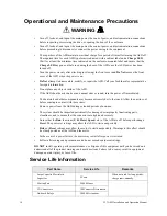
Page 16: ...dor or sound turn the power off immediately The heat sink and other components may become extremely hot to the touch Allow the unit to cool before coming in contact with these items Remove power from the ASD during extended periods of non use The system should be inspected periodically for damaged or improperly functioning parts cleanliness and to ensure that the connectors are tightened securely ...

Page 17: ... factor correction capacitor or surge absorber to the output of the ASD If the ASD is used with a motor that is equipped with a capacitor for power factor correction remove the capacitor from the motor Connecting either of these devices to the output of the ASD may cause the ASD to malfunction and trip or the output device may cause an over current condition resulting in damage to the device or th...

Page 18: ...ASD are DC Injection Braking and Dynamic Braking For further information on braking systems see DC Injection Braking Current on pg 65 and Dynamic Braking Enable on pg 68 ASD Characteristics Over current Protection Each W7 ASD model was designed for a specified operating power range The ASD will incur a trip if the design specifications are exceeded However the ASD may be operated at 100 of the spe...

Page 19: ...netic contactor MC is used between the output of the ASD and the motor it should be interlocked such that the ST CC connection is disconnected before the output contactor is opened Do Not open and then close a secondary magnetic contactor between the ASD and the motor unless the ASD is off and the motor is not rotating Note Re application of power via a secondary contact while the ASD is on or whi...

Page 20: ...light using the mounting holes on the rear of the ASD The ambient temperature rating for the W7 ASD is from 14 to 104 F 10 to 40 C The process of converting AC to DC and then back to AC produces heat During normal ASD operation up to 5 of the input energy to the ASD may be dissipated as heat If installing the ASD in a cabinet ensure that there is adequate ventilation Do Not operate the ASD with th...

Page 21: ...d conductor Power Connections Connect the 3 phase input power to the input terminals of the W7 ASD at L1 R L2 S and L3 T Connect the output terminals T1 U T2 V and T3 W of the W7 ASD to the motor The input and output conductors and terminal lugs used shall be in accordance with the specifications listed in the section titled Cable Terminal Specifications on pg 154 An inductor may be connected acro...

Page 22: ...eeding the peak voltage rating or the allowable thermal rise time of the motor insulation will reduce the life expectancy of the motor For proper operation the carrier frequency must be 2 2 kHz or above except when operating in the Constant Torque or Variable Torque modes Startup and Test Perform the following checks before turning on the unit L1 R L2 S and L3 T are connected to the 3 phase input ...

Page 23: ...put S3 Discrete Input Preset Speed 3 Multifunctional programmable discrete input S4 Discrete Input Emergency Off Multifunctional programmable discrete input RR Analog Input RR Multifunction programmable analog input 0 0 to 10 volt input 0 to 80 Hz output Reference CC Figure 8 on pg 23 RX Analog Input RX Multifunctional programmable analog input 10 to 10 VDC input 80 to 80 Hz output Reference CC Fi...

Page 24: ... page 138 See S1 Terminal on pg 119 for more information on this terminal S2 The default setting for this terminal is S2 The function of this input as S2 is to run the motor at Preset Speed 2 see Preset Speed 2 on pg 100 when it is on This input terminal may be programmed to any 1 of the 69 functions that are listed in Table 6 on page 138 See S2 Terminal on pg 120 for more information on this term...

Page 25: ...on on this terminal FP The default function of this output terminal is to output a series of pulses at a rate that is a function of the output frequency of the ASD As the output frequency of the ASD goes up so does the FP output pulse rate This terminal may be programmed to provide output pulses at a rate that is a function of the output frequency or the magnitude of any 1 of the 31 the functions ...

Page 26: ...terminals See the AM Terminal Assignment and the FM Terminal Assignment descriptions for further information on SW1 and SW2 SW1 TB1 0 1 mA 4 20 mA CN7A SW2 0 1 mA 4 20 mA Shown below are the TB1 input and output terminals of the Control Terminal Strip PCBA For further information on these terminals see pg 17 RR P24 RES F A R S1 S2 S3 S4 C C A II Terminals OUT1 OUT2 ...

Page 27: ...tocol via Program Comm Settings Consult the ASD NANOCOM User s Manual P N 10572 1 000 000 for a complete listing of the setup requirements Half or Full duplex communications is available when using RS232 RS485 communications The jumpers at the JP1 and the JP2 connectors may be moved from one position to the other to facilitate either half or full duplex operation If no jumpers are used the system ...

Page 28: ...n CNU1 Pinout Controller PCBA CNU1A Pinout EOI Pin CNU2 Pinout Controller PCBA CNU2A Pinout EOI 1 P24 P24 1 P24 P24 2 Gnd Gnd 2 Gnd Gnd 3 Tx RXA 3 Rx Tx 4 Rx TXA 4 Gnd Gnd 5 Rx TXB 5 Tx Rx 6 Tx RXB 6 Gnd Gnd 7 RS232 RS485 CNU3 Pin 7 7 Open Open 8 Gnd Gnd 8 Gnd Gnd Pin Number CN3 Pinout Controller PCBA 1 RS232 RS485 Signal 2 RS232 RS485 Signal 3 RS232 RS485 Signal Gnd 4 Shield Pin Number Function P...

Page 29: ...Circuit Configurations Figure 7 Discrete Input Figure 8 RR Input Figure 9 RX Input Figure 10 VI II Input Figure 11 P24 Output Figure 12 PP Output Figure 13 OUT1 OUT2 Output Figure 14 FP Output Figure 15 AM FM Output Figure 16 Fault Relay active fault ...

Page 30: ...d Operation Manual Typical Connection Diagram Figure 17 W7 ASD typical connection diagram Note When connecting multiple wires to the PA PB PC or PO terminals do not connect a solid wire and a stranded wire to the same terminal ...

Page 31: ... enables the Command and Frequency control functions to be carried out via the EOI The Remote mode enables the Command and Frequency control functions to be carried out via any one of the following methods Pulse Input Motorized Pot Communication Card RS232 RS485 Common TTL Binary BCD LED Keypad Option Card RX2 RX RR or VI II The input channel selection may be made via Program Utilities Command and...

Page 32: ...Rotary Encoder The Rotary Encoder will be used in this explanation and throughout this manual for the Up Down and Enter key functions The software used with the W7 ASD is menu driven thus making it a select and click environment The operating parameters of a motor may be selected and viewed or changed using the EOI To change a parameter setting go to the Program mode by pressing the MON PRG key un...

Page 33: ...mmended Remote mounting will also allow for multiple EOI mountings at one location if controlling and monitoring several ASDs from a central location is required The optional dust cover P N ASD BPC may be used to cover the front panel opening of the ASD housing after removing the EOI An EOI extender cable is required for remote mounting EOI extender cables are available in lengths of 7 10 or 15 fe...

Page 34: ...d to flammable chemicals or gasses water solvents or other fluids Turn the power on only after securing the front cover to the ASD EOI Remote Mounting w o the ASD MTG KIT Note See Figure 19 for the dimensions and the item locations referenced in steps 1 through 5 1 At the EOI mounting location identify and mark the location of the 3 80 by 3 29 hole and the 7 32 screw holes 2 Cut the 3 80 by 3 29 r...

Page 35: ...e 10 flat washers 5 Attach and secure the EOI to the front side of the Bezel plate using the four 6 32 x 5 16 pan head screws the 6 flat washers and the 6 split lock washers 6 Connect the RJ 45 extension cable s EOI ASD MTG KIT Dimensions mounting Figure 20 EOI Bezel Plate Mounting Dimensions Figure 21 Screw Length Precaution Front View Side View Back View 4 60 5 38 4 25 5 00 Bezel Plate Bezel Pla...

Page 36: ...menu items Once reaching the lowest level of a parameter group scroll to the parameter to be changed and press the Rotary Encoder The parameter takes on the reverse video format dark background light text Use the Rotary Encoder to scroll to the new value or setting Press the ESC key to exit without saving the parameter change while still in the reverse video mode or press the Rotary Encoder to acc...

Page 37: ...parameters and stops at the next parameter that has been changed Pressing the Rotary Encoder while a changed parameter is displayed accesses the settings of the changed parameter for viewing or changing Pressing ESC while the system is performing a Changed From Default search terminates the search Pressing ESC when done searching or halted at a changed parameter returns the system to the Program m...

Page 38: ...Mapping Frequency Command Screen Frequency Setting While operating in the Local mode Local LED is illuminated on the EOI the running frequency of the motor may be set from the Frequency Command screen Using the Rotary Encoder enter the desired Frequency Command value press the Enter key and then press the Run key The motor will run at the Frequency Command speed and may be changed while running Fi...

Page 39: ...ull range RX Input Displays the RX input as a percentage of its full range VI II Input Displays the VI II input as a percentage of the full range of the VI II value Note The VI II input represents two analog inputs and terminals The VI input terminal is used for a 0 10 VDC analog signal and the II input terminal is used for current loop applications such as with a 4 20 mA signal Either may be used...

Page 40: ...age and Current on pg 133 DC Voltage Shows the instantaneous DC bus voltage as a percentage of the rating of the ASD or as a voltage see Units for Voltage and Current on pg 133 Output Current Shows the instantaneous output current as a percentage of the rating of the ASD or as a current see Units for Voltage and Current on pg 133 Frequency Command Displays the current frequency command Program Scr...

Page 41: ...ward Reverse Run 0311 Upper Limit Frequency 0012 Lower Limit Frequency 0013 V f Pattern 0015 Torque Boost 1 0016 Acceleration Time 1 0009 Deceleration Time 1 0010 Acceleration Deceleration Pattern 1 0502 S Pattern Lower Limit Adjustment 0506 S Pattern Upper Limit Adjustment 0507 Fundamental 2 Base Frequency 2 0170 Maximum Voltage 2 0171 Torque Boost 2 0172 Thermal Protection 2 0173 Acceleration Ti...

Page 42: ...t Level 0732 Low output Disable Delay Time 0733 Low output Disable Boost Level 0734 Low output Disable Boost Time 0735 Low output Disable Feedback Level 0736 Low output Disable Restart Delay 0737 4 20 mA Loss Selection 0962 4 20 mA Speed Reference 0964 Frequency Command Panel N A PID Feedback Value N A Trip History RTC option required Trip Number N A Trip Type Frequency at trip Output current Outp...

Page 43: ...Setup Command N A Frequency Contrast Up Down Arrow Key 716 CHANGED FROM DEFAULT See the section titled Default Setting Changes on pg 30 N A DIRECT ACCESS Parameter Number Input N A Enable Disable Unknown Numbers UTILITIES Version CPU Version N A CPU Revision Level Main Board EEPROM Version ASD Type EOI Version Display Attributes Panel Operation Inhibit Selection 0730 Hz per User defined Unit 0702 ...

Page 44: ...uency Setpoint 2 0204 RR Speed Reference Setpoint 1 0210 RR Speed Frequency Setpoint 1 0211 RR Speed Reference Setpoint 2 0212 RR Speed Frequency Setpoint 2 0213 RX Speed Reference Setpoint 1 0216 RX Speed Frequency Setpoint 1 0217 RX Speed Reference Setpoint 2 0218 RX Speed Frequency Setpoint 2 0219 RX2 Speed Reference Setpoint 1 0222 RX2 Speed Frequency Setpoint 1 0223 RX2 Speed Reference Setpoi...

Page 45: ...hermal Protection 3 0177 Base Frequency 4 0178 Maximum Output Voltage 4 0179 Torque Boost 4 0180 Electronic Thermal Protection 4 0181 Autotune Control Setting 0400 Vector Motor Model Slip Frequency Gain 0401 Motor Constant 1 primary resistance 0402 Motor Constant 2 secondary resistance 0403 Motor Constant 3 exciting inductance 0404 Motor Constant 4 load inertia 0405 Motor Constant 5 leakage induct...

Page 46: ...ve Address 0860 Transmit Address 0861 Speed Reference Station 0862 Speed Reference Address 0863 Torque Reference Station 0865 Torque Reference Address 0866 Fault Detect Station Number 0868 Station Mode 0869 S20 Reset 0899 S20 Error Mode 0850 Error Detect Time 0851 1 Scan Receive 0831 2 Scan Receive 0832 3 Scan Receive 0833 4 Scan Receive 0834 5 Scan Receive 0835 6 Scan Receive 0836 1 Scan Transmit...

Page 47: ...l 0601 Overvoltage Stall 0305 Overvoltage Stall Level 0626 Overvoltage Stall Level fast 0625 Continuing Stall Period 0452 Stall Prevention During Regeneration 0453 DC Injection Start Frequency 0250 DC Injection Current 0251 DC Injection Time 0252 DC Injection On During Direction Change 0253 Motor Shaft Stationary Control 0254 Emergency Off Mode Selection 0603 Emergency Off Mode Time 0604 Number of...

Page 48: ...Circuit Test 0613 Output Short Circuit Test Duration 0614 Overtorque Trip 0615 Overtorque Trip Alarm Level positive torque 0616 Overtorque Trip Alarm Level negative torque 0617 Overtorque Detection Time 0618 Brake Fault Internal Timer 0630 Release After Run Timer brake 0632 Inrush Current Suppression Time ms relay delay 0608 Interlock With ST 0609 Adding Input Selection 0660 Multiplying Input Sele...

Page 49: ...0101 FP N A Terminal Delays Input F 0140 R 0141 ST 0142 RES 0143 S1 S4 0144 S5 S16 0145 Terminal Delays Output OUT1 On Delay 0150 OUT1 Off Delay 0160 OUT2 On Delay 0151 OUT2 Off Delay 0161 FL On Delay 0152 FL Off Delay 0162 OUT4 On Delay 0153 OUT4 Off Delay 0163 OUT5 On Delay 0154 OUT5 Off Delay 0164 OUT6 On Delay 0155 OUT6 Off Delay 0165 OUT7 On Delay 0156 OUT7 Off Delay 0166 Program Menu Navigat...

Page 50: ... Settings 0290 Preset Speed 12 Settings 0291 Preset Speed 13Settings 0292 Preset Speed 14 Settings 0293 Preset Speed 15 Settings 0294 SPECIAL CONTROL Startup Frequency 0240 End Frequency 0243 Run Frequency 0241 Run Frequency Hysteresis 0242 Jump Frequency 1 0270 Jump Frequency 1 Bandwidth 0271 Jump Frequency 2 0272 Jump Frequency 2Bandwidth 0273 Jump Frequency 3 0274 Jump Frequency 3 Bandwidth 027...

Page 51: ...Commercial Power Hold Time 0358 PANEL CONTROL Panel Direction 0008 Ramped PWM 0963 Panel PID Control 0724 Panel Reset Selection 0722 Panel Acceleration Deceleration Selection 0504 Panel V f Group Selection 0720 Panel Stop Pattern 0721 Program Menu Navigation Primary Menu Sub Menu Parameter Name Parameter Number ...

Page 52: ...n Numbers Parameter Name No Parameter Name No Command Mode 0003 Preset Speed 4 0021 Frequency Mode 1 0004 Preset Speed 5 0022 FM Terminal Assignment 0005 Preset Speed 6 0023 FM Terminal Adjustment 0006 Preset Speed 7 0024 Auto Setup for 50 Hz 0007 Low Speed Signal Output Frequency 0100 Auto Setup for 60 Hz Speed Reach Setting Frequency 0101 Restore Factory Defaults Speed Reach Detection Band 0102 ...

Page 53: ...cy Setpoint 1 0223 OUT7 On Delay 0156 RX2 Speed Reference Setpoint 2 0224 OUT1 Off Delay 0160 RX2 Speed Frequency Setpoint 2 0225 OUT2 Off Delay 0161 RX2 Torque Reference Setpoint 1 0226 FL Off Delay 0162 RX2 Torque Reference Setpoint 2 0227 OUT4 Off Delay 0163 BIN Speed Reference Setpoint 1 0228 OUT5 Off Delay 0164 BIN Speed Frequency Setpoint 1 0229 OUT6 Off Delay 0165 BIN Speed Reference Refere...

Page 54: ...0390 Break Make Auto Restart 0301 Preset Speed 11 Direction see Preset Speed 1 0391 Ridethrough Mode 0302 Preset Speed 12 Direction see Preset Speed 1 0392 Number of Retries 0303 Preset Speed 13 Direction see Preset Speed 1 0393 Dynamic Braking Enable 0304 Preset Speed 14 Direction see Preset Speed 1 0394 Overvoltage Stall 0305 Preset Speed 15 Direction see Preset Speed 1 0395 Maximum Output Volta...

Page 55: ...orque Trip Alarm Level positive torque 0616 Low Output Disable Boost Time 0735 Overtorque Trip Alarm Level negative torque 0617 Low Output Disable Feedback Level 0736 Overtorque Detection Time 0618 Low Output Disable Restart Delay Time 0737 Cooling Fan Control 0620 TTL Baud Rate 0800 Cumulative Run timer Alarm Setting 0621 Parity RS232 RS485 TTL 0801 Abnormal Speed Detection Filter Time 0622 ASD N...

Page 56: ...43 Switch on the Fly 0961 4 Scan Transmit 0844 4 20 mA Loss Selection 0962 5 Scan Transmit 0845 Ramped PWM Enable 0963 6 Scan Transmit 0846 4 20 mA Speed Reference 0964 S20 Error Mode 0850 User Unit 1 0965 Error Detect Time 0851 User defined Unit Character 2 see User Unit 1 0966 Receive Address 0860 User defined Unit Character 3 see User Unit 1 0967 Transmit Address 0861 User defined Unit Characte...

Page 57: ...eed Hold Last 0 Hz RS232 RS485 Control Common Serial Control Panel Control Fault Disable Parameter Type Selection List Factory Default Disable Changeable During Run No 4 20 mA Speed Reference Program Feedback Settings 4 20 mA Speed Ref This setting provides a value to be used in the event that Setting is chosen for the 4 20 mA Loss selection Parameter Type Numerical Factory Default 0 0 Changeable ...

Page 58: ...itions as the output frequency of the ASD goes up so does the output voltage linear acceleration The ASD has the ability to modify the relationship between frequency and voltage automatically to produce smoother operation or increased starting torque Parameter Type Numerical Factory Default ASD dependent Changeable During Run Yes Minimum 0 1 Maximum 6000 Units Seconds Accel 2 Time Program Fundamen...

Page 59: ...of the available accel decel patterns Parameter Type Selection List Factory Default Linear Changeable During Run No Changeable During Run Yes Linear acceleration and deceleration is the default pattern and is used on most applications S pattern 1 is used for applications that require quick acceleration and deceleration This setting is also popular for applications that require shock absorption at ...

Page 60: ...rn 2 S Pattern 1 Linear Parameter Type Numerical Factory Default Linear Changeable During Run No Accel Decel Special Display Resolution Program Utilities Display Attributes Acc Dec Special Display Resolution This parameter sets the number of decimal places to be displayed for Accel Decel functions Parameter Type Numerical Factory Default 0 1 Changeable During Run Yes Minimum 0 01 Maximum 1 Adding ...

Page 61: ...erminal Settings AM FM AM AM Terminal Adjustment This function is used to calibrate the AM analog output terminal To calibrate the AM analog output connect a meter current or voltage as described at the AM Terminal Assignment parameter With the ASD running at a known frequency adjust this parameter until the running frequency produces the desired DC level output at the AM terminal Parameter Type N...

Page 62: ...ettings Autotune Disabled Reset Motor Defaults Enable Autotune on Run Command Parameter Type Selection List Factory Default Disabled Changeable During Run No Autotune Enable Program Motor Settings Autotune Enable This parameter Enables Disables the Autotune function Parameter Type Selection List Factory Default Enabled Changeable During Run No Base Frequency 1 Program Motor Settings Base Frequency...

Page 63: ... Maximum Output Voltage 3 parameter There are four Base Frequency profile settings 1 4 This parameter is used only when the parameters for motor set 3 are configured and selected Motor set 3 may be activated via a properly configured discrete input terminal For proper motor operation the Base Frequency should be set for the name plated frequency of the motor Parameter Type Numerical Factory Defaul...

Page 64: ... BIN Speed Frequency 1 Set BIN Speed Frequency 2 and Set the binary input value of 255D BIN Speed Ref 2 that represents the BIN Speed Frequency 2 Note 255D is the decimal equivalent of the 8 bit BIN word with all input terminals set to one 255 decimal 11111111 binary Once set as the BIN input word changes the directional information and the output frequency of the ASD will vary in accordance with ...

Page 65: ...umerical Factory Default 0 00 Changeable During Run Yes Minimum 0 00 Maximum 100 00 Units BIN Speed Reference Reference 2 Program Frequency Settings Speed Reference Setpoints BIN BIN Speed Reference Setpoint 2 This parameter is used to set the direction gain and bias of the discrete input terminals when using the discrete input terminals as the control input while operating in the Speed Control or...

Page 66: ...alue of 255D BIN Speed Ref 2 that represents BIN Torque Reference 2 This is accomplished by establishing an associated V f output pattern for a given BIN binary input This parameter sets BIN Torque Reference 1 and is the output torque value that is associated with the setting of BIN Speed Reference 1 when operating in the Torque control mode This value is entered as 250 to 250 of the output torque...

Page 67: ... momentary power failure Settings Off Power Failure Make Break ST Both Parameter Type Selection List Factory Default Off Changeable During Run No Command Mode Program Utilities Command and Frequency Settings Command Mode Select The Command Mode Selection establishes the source of the command input for the ASD Command inputs include Run Stop Forward etc Settings Use Control Terminal Strip Terminal ...

Page 68: ...ication error during a transmission the command that was transmitted may be cleared or held Changes made to this parameter require that the power be cycled Off then On for the changes to take effect Settings 0 Command Request Cleared 1 Command Request Held Parameter Type Selection List Factory Default 0 Changeable During Run No Communication Interval TTL Program Communication Settings TTL Res Time...

Page 69: ... range Changes made to this parameter require that the power be cycled Off then On for the changes to take effect Parameter Type Numerical Factory Default 0 00 Changeable During Run Yes Minimum 0 00 Maximum 100 0 Units Frequency Settings Communications Reference Setpoint 2 Program Communications Settings Comm Reference Setpoint 2 This parameter is used to set the gain and bias of the Communication...

Page 70: ...r sets the Communications Speed 2 Changes made to this parameter require that the power be cycled Off then On for the changes to take effect Parameter Type Numerical Factory Default 80 0 Changeable During Run Yes Minimum 0 0 Maximum Max Freq Units Hz Cooling Fan Control Program Protection Settings Cooling Fan Control This parameter sets the cooling fan run time command Settings Automatic Always On...

Page 71: ... entered in DC Injection Braking Time times out The intensity of the DC current used while braking determines how fast the motor will come to a stop and may be set at the DC Injection Braking Current parameter The intensity setting is entered as a percentage of the full load current of the ASD Note DC Injection Braking is also used to preheat the motor or to keep the rotor from spinning freely whe...

Page 72: ...parameter specifies the time in seconds for the ASD output to go from the Maximum Frequency to 0 0 Hz for the 2 Deceleration profile The accel decel pattern may be set using Accel Decel 2 Pattern This setting is also used to determine the deceleration rate of the Motorized Pot function Note A deceleration time shorter than the load will allow may cause nuisance tripping and mechanical stress to lo...

Page 73: ...hen both the F and R control terminals are activated Parameter Type Selection List Factory Default Reverse Changeable During Run No Disable Forward Run Disable Reverse Run Program Fundamental Parameters Fundamental 1 Disable Forward Reverse Run This parameter Enables Disables the Forward Run or Reverse Run mode If either direction is disabled commands received for the disabled direction will not b...

Page 74: ...roviding the proper information at the DBR parameters Dynamic Braking Resistor DBR Capacity Dynamic Braking Resistance and DC Injection Braking Current For additional information on selecting the proper resistance value for a given application contact Toshiba s Marketing Department Parameter Type Selection List Factory Default Disabled Changeable During Run No Dynamic Braking Resistance Program Pr...

Page 75: ...ype Numerical Factory Default 1 00 Changeable During Run Yes Minimum 0 00 Maximum 2 50 Units Seconds Earth Fault Trip Delay Program Protection Settings EF Trip Delay In the event that the Earth Fault Trip activation criteria is met a timer begins to count down to zero Upon reaching zero the Earth Fault Trip is activated This parameter sets the start time of the count down timer Parameter Type Nume...

Page 76: ...Numerical Factory Default 100 0 Changeable During Run Yes Minimum 10 0 Maximum 100 0 Units Electronic Thermal Protection 3 Program Motor Settings Electronic Thermal Protection 3 This parameter specifies the motor overload current level for motor set 3 This value is entered as either a percentage of the full load rating of the ASD or as the FLA of the motor The unit of measurement for this paramete...

Page 77: ...ime Program Protection Settings Emergency Off Mode Time When DC Injection is used as a function of receiving an Emergency Off command this parameter determines the time that the DC Injection braking is applied to the motor Parameter Type Numerical Factory Default 0 10 Changeable During Run Yes Minimum 0 00 Maximum 10 00 Units Seconds End Frequency Program Special Control End Frequency This paramet...

Page 78: ...tput terminals by the programmed value The on and off delay times of the FL terminals may be adjusted to provide more response time to the device that is connected to the output terminals Parameter Type Numerical Factory Default 2 0 Changeable During Run No Minimum 2 0 Maximum 200 0 Units mS FL On Delay Program Terminal Settings Terminal Delays Output Terminal Delays FL FL On Delay This parameter ...

Page 79: ...d in Table 8 on page 142 The FM analog output has a maximum resolution of 1 1024 SW 2 may be switched to allow for the full range output to be either 0 1 mA or 4 20 mA when providing an output current or either 0 1 or 1 7 5 volts when providing an output voltage at this terminal Parameter Type Selection List Factory Default Output Frequency Changeable During Run Yes FM Terminal Adjustment Program ...

Page 80: ...nt Program Terminal Settings Output Terminals FP FP Terminal Adjustment This parameter sets the full scale reading of the FP terminal The full scale reading of the monitored variable selected in FP Terminal Setting may be set here Parameter Type Numerical Factory Default 3 840 Changeable During Run Yes Minimum 1 000 Maximum 43 200 Units kHz Frequency Command Panel Program System Information and Se...

Page 81: ...de 2 is set up as the primary control parameter See the Reference Priority Selection parameter for additional information on this setting The Frequency Mode setting establishes the source of the frequency control input for the ASD Settings Use VI II Use RR Use RX Use Option Card RX2 Use LED Keypad Option Use Binary BCD Input Use Common Serial TTL Use RS232 RS485 Use Communication Card Use Motorize...

Page 82: ...t This parameter allows the user to input a quantity to be displayed on the EOI that is proportional to the output frequency of the drive This feature is useful when the output of a process is moved along at a rate that is proportional to the output frequency of the drive Parameter Type Numerical Factory Default 0 00 Changeable During Run Yes Minimum 0 00 Maximum 200 0 Units Hz UDU Input Feedback ...

Page 83: ...startup inrush current may be suppressed for up to 2 5 seconds This parameter determines the length of the inrush current suppression Parameter Type Numerical Factory Default 0 30 Changeable During Run No Minimum 0 30 Maximum 2 50 Units Seconds Integral I Gain Program Feedback Settings Integral Gain This parameter determines the degree that the Integral function affects the output signal when usin...

Page 84: ...og mode Settings Deceleration Stop Coast Stop DC Injection Braking Stop Parameter Type Selection List Factory Default Coast Stop Changeable During Run Yes Jump Frequency 1 Program Special Control Jump Frequency 1 This parameter sets a frequency that during acceleration deceleration or while running will not be output from the ASD This parameter operates in conjunction with the bandwidth setting of...

Page 85: ...ial Control Jump Frequency 1 Bandwidth This parameter establishes a plus or minus value for Jump Frequency 1 See the Jump Frequency 1 parameter for further information on this setting Parameter Type Numerical Factory Default 0 0 Changeable During Run Yes Minimum 0 0 Maximum 30 00 Units Hz Jump Frequency 2 Bandwidth Program Special Control Jump Frequency 2 Bandwidth This parameter establishes a plu...

Page 86: ...List Factory Default 0 00 Changeable During Run No Minimum 100 00 Maximum 100 00 Lock on Rate Program Protection Settings Lock on Rate After a momentary power outage the ASD may have to startup into a spinning motor The Lock on Rate is the difference between the time that the RPM of the motor is determined by the ASD and the time that the ASD outputs a drive signal to the motor The Speed Search pa...

Page 87: ...ay decrease the output signal Parameter Type Numerical Factory Default 50 00 Changeable During Run Yes Minimum 0 00 Maximum 50 00 Units Lower Limit Frequency Program Fundamental Parameters Fundamental 1 Lower Limit Frequency This parameter sets the lowest frequency that the ASD will accept as a frequency command or frequency setpoint The ASD will output frequencies lower than the Lower Limit Frequ...

Page 88: ...le Feedback Level The Low Output Disable Feedback Level sets a frequency level that until the output of the ASD drops below this setting the Restart Delay Timer does not start Parameter Type Numerical Factory Default 0 0 Changeable During Run Yes Minimum 0 0 Maximum Max Freq Units Hz Low Output Disable Restart Delay Time Program PID Setup Low output Disable Restart Delay The Low Output Disable Res...

Page 89: ...am Fundamental Parameters Fundamental 1 Maximum Output Frequency This setting determines the absolute maximum frequency that the ASD can output This setting is also referred to as FH Accel decel times are calculated based on the Maximum Frequency setting Note This setting may not be lower than the Upper Limit setting Parameter Type Numerical Factory Default 80 0 Changeable During Run No Minimum 30...

Page 90: ...lue of the output voltage of the ASD for the 4 Motor Set Regardless of the programmed value the output voltage cannot be higher than the input voltage The actual output voltage will be influenced by the input voltage of the ASD and the Supply Voltage Compensation parameter setting Parameter Type Numerical Factory Default ASD dependent Changeable During Run Yes Minimum 0 0 Maximum ASD dependent Uni...

Page 91: ...onstants to tune the motor This setting motor tuning is required to use the Vector Control Automatic Torque Boost or Automatic Energy saving functions Parameter Type Numerical Factory Default ASD dependent Changeable During Run No Minimum 0 00 Maximum Open Units Ω Motor Constant 3 Program Motor Settings Motor Constant 3 Exciting Inductance This parameter is used to input the excitation inductance ...

Page 92: ...half of the amperage setting of the DC Injection Braking Current parameter into a stopped motor This feature is useful in preheating the motor or to keep a stopped motor from spinning freely Motor Shaft Stationary Control starts after the DC injection brake stops the motor and continues until ST to CC is opened power is turned off receiving an Emergency Off command or this parameter is changed To ...

Page 93: ...Option Override Multiplication Gain parameter is used as the multiplier Settings PID Control Disabled VI II RR RX RX2 option Setting LED Keypad Option Only Proportional Integral Derivative PID A closed loop control technique that seeks error minimization by reacting to three values One that is proportional to the error one that is representative of the error and one that is representative of the r...

Page 94: ...ON control terminal exists only in memory and is considered to always be in its True or connected to CC state It is often practical to assign this terminal to a function that the user desires to be maintained regardless of external conditions or operations This parameter sets the programmable ON terminal to 1 of the 69 possible functions that are listed in Table 6 on page 138 In addition the input...

Page 95: ...ge the state of the OUT2 A C output contacts this parameter delays the response of the contacts by the programmed value see waveforms at FL Off Delay The on and off delay times of the OUT2 contacts may be adjusted to provide more response time to the device that is connected to the output terminals Parameter Type Numerical Factory Default 2 0 Changeable During Run No Minimum 2 0 Maximum 200 0 Unit...

Page 96: ...8 possible functions that are listed in Table 7 on page 141 The on and off delay times of the OUT4 contacts may be adjusted to provide more response time to the device that is connected to the output terminals In addition the output contacts must be specified as Normally Open or Normally Closed Parameter Type Selection List Factory Default Lower Limit Changeable During Run No OUT5 Off Delay Progra...

Page 97: ...lays OUT6 On Delay This parameter delays the response of the OUT6 output contacts by the programmed value see waveforms at FL On Delay The delay may be increased to prevent relay chatter Parameter Type Numerical Factory Default 2 0 Changeable During Run No Minimum 2 0 Maximum 200 0 Units mS OUT6 Terminal Program Terminal Settings Output Terminals OUT6 Terminal Assignment This parameter sets the fu...

Page 98: ...y Default OC Alarm Changeable During Run No Output Phase Loss Detection Program Protection Settings Output Phase Loss Detection This parameter Enables Disables the monitoring of each phase of the 3 phase output signal U V or W of the ASD If either line is missing inactive or not of the specified level the ASD incurs a trip Parameter Type Selection List Factory Default Disabled Changeable During Ru...

Page 99: ...cy Range This parameter sets the upper level of the Base Frequency range that once exceeded will cause an Overspeed Detected alert Parameter Type Numerical Factory Default 0 0 Changeable During Run Yes Minimum 0 0 Maximum 30 0 Units Hz Overtorque Detection Time Program Protection Settings Overtorque Detection Time This parameter sets the amount of time that the overtorque condition may exceed the ...

Page 100: ...lt Stall This parameter Enables Disables the Overvoltage Stall function When enabled this function causes the ASD to extend the decel time when the DC bus voltage increases due to transient voltage spikes regeneration supply voltage out of specification etc in an attempt to reduce the bus voltage Settings Enabled Disabled Enabled Forced Shorted Deceleration Parameter Type Selection List Factory De...

Page 101: ...leration 1 Acceleration Deceleration 2 Acceleration Deceleration 3 Acceleration Deceleration 4 Parameter Type Selection List Factory Default Acceleration Deceleration 1 Changeable During Run Yes Panel Direction Program Panel Control Panel Direction This parameter sets the motor direction while operating from the keypad Parameter Type Selection List Factory Default Forward Changeable During Run Yes...

Page 102: ...5 TTL This parameter plays a role in the setup of the communications network by establishing the Parity setting of the communications link The communications network includes other ASDs and Host Control computers that monitor the status of the ASD s transfers commands and loads or modifies the parameter settings of the ASD Changes made to this parameter require that the power be cycled Off then On...

Page 103: ...ogram Utilitites Command and Frequency Settings Frequency Mode 1 Select Use Pulse Input Program Utilitites Command and Frequency Settings Command Mode Select any setting Provide a Run command F and or R Speed Direction Control Perform the following setup to allow the system to perform PG Speed Direction control Set PG Speed Frequency 1 Set the PG input pulse count that represents PG Speed Frequenc...

Page 104: ...d as a percentage of the full range The range of values for this parameter is 100 to 100 of the PG input pulse count range See PG Speed Frequency Setpoint 1 for further information on this setting Parameter Type Numerical Factory Default 0 00 Changeable During Run Yes Minimum 100 0 Maximum 100 0 Units PG Speed Reference Setpoint 2 Program Frequency Settings Speed Reference Setpoints PG PG Speed Re...

Page 105: ... Disabled On Trip At Frequency Trip or At Frequency Parameter Type Selection List Factory Default Disabled Changeable During Run No Power Line Switching Frequency Program Special Control Power Line Switching Frequency With the Power Switching parameter enabled this parameter sets the frequency at which the At Frequency selection of the Power Switching parameter is activated If the Power Switching ...

Page 106: ...Preset Speed is used 5 From the Frequency Command screen only place the system in the Remote mode Local Remote LED Off 6 Provide a Run command connect F and or R to CC Connect S1 to CC to run Preset Speed 1 S1 to CC 0001 binary With S1 S4 configured to output Preset Speeds 0001B 1111B may be applied to S1 S4 of the Control Terminal Strip to run the associated Preset Speed of the truth table If bid...

Page 107: ...0101 and is identified as Preset Speed 5 The binary number is applied to S1 S4 of the Control Terminal Strip to output the Preset Speed see Preset Speed 1 for further information on this parameter Parameter Type Numerical Factory Default 0 0 Changeable During Run Yes Minimum Lower Limit Maximum Upper Limit Units Hz Preset Speed 6 Program Preset Speeds 6 This parameter assigns an output frequency t...

Page 108: ... and is identified as Preset Speed 10 The binary number is applied to S1 S4 of the Control Terminal Strip to output the Preset Speed see Preset Speed 1 for further information on this parameter Parameter Type Numerical Factory Default 0 00 Changeable During Run Yes Minimum Lower Limit Maximum Upper Limit Units Hz Preset Speed 11 Program Preset Speeds 11 This parameter assigns an output frequency t...

Page 109: ...1 and is identified as Preset Speed 15 The binary number is applied to S1 S4 of the Control Terminal Strip to output the Preset Speed see Preset Speed 1 for further information on this parameter Parameter Type Numerical Factory Default 0 00 Changeable During Run Yes Minimum Lower Limit Maximum Upper Limit Units Hz Preset Speed Mode Control Program Preset Speeds Mode Enables Disables the use of the...

Page 110: ...quency as listed below for a given ASD will reduce the capability of the ASD Parameter Type Numerical Factory Default 2 200 Changeable During Run No Minimum 0 500 Maximum ASD dependent Units kHz Ramped PWM Enable Program Special Control Ramped PWM Enable Enables Disables the variable PWM frequency Parameter Type Selection List Factory Default Disabled Changeable During Run No Receive Address Progr...

Page 111: ...en determining when to toggle the output control between the Frequency Mode 1 selection and the Frequency Mode 2 selection If Freq 1 Priority is selected here and the commanded frequency exceeds the Mode 1 2 SW Switching Freq setting then the Freq Mode 1 selection has priority over the Freq Mode 2 selection If Freq 2 Priority is selected here and the commanded frequency exceeds the Mode 1 2 SW Swi...

Page 112: ...Numerical Factory Default 8 0 Changeable During Run No Minimum 2 0 Maximum 200 0 Units mS Ridethrough Mode Program Protection Settings Ridethrough Mode Enables Disables the Ridethrough function In the event of a momentary power outage or a make break at ST to CC when enabled the Ridethrough function uses regenerative energy to maintain the control circuitry settings Regenerated energy is not used ...

Page 113: ...R Speed Ref 2 that represents RR Speed Frequency 2 Once set as the RR input voltage changes the output frequency of the ASD will vary in accordance with the above settings This parameter sets RR Speed Frequency 1 and is the frequency that is associated with the setting of RR Speed Reference 1 when operating in the Speed Control mode Parameter Type Numerical Factory Default 0 0 Changeable During Ru...

Page 114: ...Type Numerical Factory Default 0 00 Changeable During Run Yes Minimum 0 0 Maximum 100 0 Units RR Speed Reference Setpoint 2 Program Frequency Settings RR RR Speed Reference Setpoint 2 This parameter is used to set the gain and bias of the RR input terminal when the RR terminal is used as the control input while operating in the Speed Control or the Torque Control mode See RR Speed Frequency 1 for ...

Page 115: ...d V f output pattern for a given RR input level This parameter sets RR Torque Reference 1 and is the output torque value that is associated with the setting of RR Speed Reference 1 when operating in the Torque control mode This value is entered as 0 0 to 250 of the output torque range Parameter Type Numerical Factory Default 0 00 Changeable During Run Yes Minimum 0 0 Maximum 250 0 Units Torque Set...

Page 116: ... Off then On for the changes to take effect Settings None RS232 RS485 Alarm TTL None RS232 RS485 Trip TTL None RS232 RS485 None TTL Alarm RS232 RS485 Alarm TTL Alarm RS232 RS485 Trip TTL Alarm RS232 RS485 None TTL Trip RS232 RS485 Alarm TTL Trip RS232 RS485 Trip TTL Trip Parameter Type Selection List Factory Default 485 Alarm TTL None Changeable During Run Yes RS232 RS485 Communication Time Out Ti...

Page 117: ...es made to this parameter require that the power be cycled Off then On for the changes to take effect Parameter Type Numerical Factory Default 0 00 Changeable During Run Yes Minimum 0 00 Maximum 2 00 Units Seconds RS232 RS485 Wire Count Program Communication Settings RS232 RS485 Wire Count This parameter sets the communications protocol to the 2 or 4 wire method Changes made to this parameter requ...

Page 118: ...he Run Frequency Hysteresis parameter provides a plus or minus value for the Run Frequency thus establishing a frequency band During acceleration the ASD will not output a signal to the motor until the lower level of the band is reached During deceleration the ASD will continue to output the programmed deceleration output signal to the motor until the lower level of the band is reached at which ti...

Page 119: ... input signal level RX2 Speed Ref 2 that represents RX2 Speed Frequency Setpoint 2 Once set as the RX2 input voltage changes the directional information and the output frequency of the ASD will vary in accordance with the above settings This parameter sets RX2 Speed Frequency 1 and is the frequency that is associated with the setting of RX2 Speed Reference 1 when operating in the Speed Control mod...

Page 120: ...e Numerical Factory Default 0 00 Changeable During Run Yes Minimum 100 0 Maximum 100 0 Units RX2 Speed Reference Setpoint 2 Program Frequency Settings Speed Reference Setpoints RX2 RX2 Speed Reference Setpoint 2 This parameter is used to set the direction gain and bias of the RX2 input terminal when the RX2 terminal is used as the control input while operating in the Speed Control or the Torque Co...

Page 121: ...ated V f output pattern for a given RX2 input level This parameter sets RX2 Torque Reference 1 and is the output torque value that is associated with the setting of RX2 Speed Reference Setpoint 1 when operating in the Torque control mode This value is entered as 250 to 250 of the rated torque Parameter Type Numerical Factory Default 0 00 Changeable During Run Yes Minimum 250 0 Maximum 250 0 Units ...

Page 122: ... Speed Frequency Setpoint 2 Once set as the RX input voltage changes the directional information and the output frequency of the ASD will vary in accordance with the above settings This parameter sets RX Speed Frequency 1 and is the frequency that is associated with the setting of RX Speed Reference Setpoint 1 when operating in the Speed Control mode Parameter Type Numerical Factory Default 0 0 Ch...

Page 123: ...e Numerical Factory Default 0 00 Changeable During Run Yes Minimum 100 0 Maximum 100 0 Units RX Speed Reference Setpoint 2 Program Frequency Settings Speed Reference Setpoints RX Speed Frequency Setpoint 2 This parameter is used to set the direction gain and bias of the RX input terminal when the RX terminal is used as the control input while operating in the Speed Control or the Torque Control mo...

Page 124: ... associated V f output pattern for a given RX input level This parameter sets RX Torque Reference 1 and is the output torque value that is associated with the setting of RX Speed Reference 1 when operating in the Torque control mode This value is entered as 250 to 250 of the rated torque Parameter Type Numerical Factory Default 0 00 Changeable During Run Yes Minimum 250 0 Maximum 250 0 Units Torqu...

Page 125: ...st if the system is powered down or reset In addition the input terminal must be specified as Normally Open or Normally Closed This parameter sets the programmable S10 terminal to 1 of the 69 possible functions that are listed in Table 6 on page 138 Parameter Type Selection List Factory Default Unassigned Changeable During Run No S11 Terminal Program Terminal Settings Input Terminals S11 Terminal ...

Page 126: ... FL Off Delay The delay may be increased to provide additional electrical noise immunity or to prevent the ASD from responding to contact bounce or chatter Parameter Type Numerical Factory Default 8 0 Changeable During Run No Minimum 2 0 Maximum 200 0 Units mS S2 Terminal Program Terminal Settings Input Terminals S2 Terminal Assignment This parameter selects the functionality of the S2 discrete in...

Page 127: ...n or reset In addition the input terminal must be specified as Normally Open or Normally Closed This parameter sets the programmable S5 terminal to 1 of the 69 possible functions that are listed in Table 6 on page 138 Parameter Type Selection List Factory Default Unassigned Changeable During Run No S5 S16 Terminal Delay Program Terminal Settings Terminal Delays Input Terminal Delays S5 S16 Delays ...

Page 128: ...out the ASD Multicom option board the S7 terminal settings will be stored in volatile memory The terminal settings will be lost if the system is powered down or reset In addition the input terminal must be specified as Normally Open or Normally Closed This parameter sets the programmable S7 terminal to 1 of the 69 possible functions that are listed in Table 6 on page 138 Parameter Type Selection L...

Page 129: ...entary power outage the output signal of the ASD will cease Upon restoration of power the ASD will output a low level signal that will be used to determine the rotation speed of the rotor The low level signal will start scanning the motor at FH and decrease until it reaches 0 0 Hz or it matches the signal produced by the turning rotor Once the rate of rotation is determined the ASD will provide th...

Page 130: ...r Type Selection List Factory Default 1 0 Changeable During Run No Units Seconds Search Method Program Protection Settings Search Method In the event of a momentary power outage this parameter may be used to set the starting point frequency of the scanning signal that is used to determine the rotor speed or depending on the selection this parameter may be used to select the method used to search f...

Page 131: ...ard motor Note The Soft Stall setting may affect acceleration times and patterns Settings V f Motor Soft Stall Only V f Motor Disable Trip Disable Stall V f Motor Enable Trip Enable Stall V f Motor Trip Only Standard Motor Soft Stall Only Standard Motor Disable Trip Disable Stall Standard Motor Enable Trip Enable Stall Standard Motor Trip Only Parameter Type Selection List Factory Default Trip Onl...

Page 132: ...width will provide a signal at an output terminal that can close an appropriately configured output contact Parameter Type Numerical Factory Default 2 5 Changeable During Run Yes Minimum 0 0 Maximum Max Freq Units Hz Speed Reference Address Program Communication Settings S20 Settings The S20 system is Toshiba s high speed fiber optic communication system This function is unavailable at the time of...

Page 133: ...uring startup the output frequency of the ASD will accelerate to the programmed setting Output frequencies below the Startup Frequency will not be output from the ASD during startup However once reaching the Startup Frequency speed values below the Startup Frequency may be output from the ASD Parameter Type Numerical Factory Default 0 10 Changeable During Run Yes Minimum 0 0 Maximum 10 0 Units Hz ...

Page 134: ...s the F Forward and R Reverse control terminals for the secondary function of Standby Closing a set of contacts to either F or R will cause the ASD to accelerate the motor to the programmed setpoint of F or R Opening the F and R contact will disable the ASD and the motor will coast to a stop The control terminal ST may be configured for other functions Parameter Type Selection List Factory Default...

Page 135: ...torque for high inertia loads by increasing the output voltage at frequencies below of the 1 Base Frequency setting The value programmed as a boost percentage establishes an output voltage vs output frequency relationship to be used to start the motor or to provide smoother operation Note Setting an excessive Torque Boost level may cause nuisance tripping and mechanical stress to loads Parameter T...

Page 136: ...D dependent Changeable During Run Yes Minimum 0 0 Maximum 30 0 Units Torque Reference Address Program Communication Settings Torque Reference Address The S20 system is Toshiba s high speed fiber optic communication system This function is unavailable at the time of this release Parameter Type Selection List Factory Default 0 Torque Reference Station Program Communication Settings Torque Reference ...

Page 137: ... 19200 38400 Parameter Type Selection List Factory Default 9600 Changeable During Run Yes TTL Master Output Program Communication Settings TTL Master Output In a master follower configuration this setting determines the output parameter of the master ASD that will be used to control the applicable follower ASDs Note Select Normal if RS485 Master Output is configured as a Master Output controller O...

Page 138: ...No Minimum 0 00 Maximum 10 00 Units Seconds Undervoltage Stall Level Program Protection Settings Undervoltage Stall Level This parameter sets the low end of the DC bus voltage threshold that once it drops below this setting will activate the Ridethrough feature Activation may be the result of a momentary power loss or an excessive load on the bus voltage Once activated the system will attempt to m...

Page 139: ... output frequencies higher than the Upper Limit Frequency but lower than the Maximum Frequency when operating in the PID Control mode Torque Control mode or the Vector Control modes sensorless or feedback Note This setting may not be higher than the Maximum Frequency setting Parameter Type Numerical Factory Default 60 0 Changeable During Run Yes Minimum 0 0 Maximum Max Freq Units Hz User Unit 1 Pr...

Page 140: ...I II terminal VI II Input Speed Control Setup Perform the following setup to allow the system to receive Speed control input at the VI II input terminal Program Utilities Command and Frequency Settings Command Mode Select Terminal Block Program Utilities Command and Frequency Settings Frequency 1 Mode Select VI II Provide a Run command F and or R Speed Control Perform the following setup to allow ...

Page 141: ...d control mode or is associated with the VI II Torque Reference Setpoint 1 when operating in the Torque control mode This value is entered as 0 0 to 100 of the 0 0 to 10 VDC VI II input signal range The default value for this parameter is 20 The II input is commonly used for the 4 20 mA current loop signal where 4 mA equals 20 of a 20 mA signal If the VI input is used 0 10 VDC input this parameter...

Page 142: ...ciated V f output pattern for a given VI II input level This parameter sets VI II Torque Reference 1 and is the output torque value that is associated with the setting of VI II Speed Reference Setpoint 1 when operating in the Torque control mode This value is entered as 0 to 250 of the rated torque Parameter Type Numerical Factory Default 0 00 Changeable During Run Yes Minimum 0 0 Maximum 250 0 Un...

Page 143: ...he degree of voltage compensation during dead time by increasing or decreasing the on time of the programmed PWM just prior to the start of the dead time Settings Disabled On Off Vout Limit On Vout Limit Parameter Type Selection List Factory Default On Changeable During Run Yes Supply Voltage Compensation Supply Voltage Compensation ...

Page 144: ...e if using a multiple motor profile configuration Motor 3 4 Motor 3 to 4 Switching Motor control may be switched between the Motor 3 profile and the Motor 4 profile if using a multiple motor profile configuration Torque Lim 1 2 Torque Limit 1 to 2 Switching Torque control may be switched between the Torque Limit 1 profile and the Torque Limit 2 profile if using a multiple profile configuration Tor...

Page 145: ...of the connection until the Lower Limit is reached The Frequency Mode setting must be set to Motorized Pot Simulation The MOP deceleration rate is determined by the Decel 2 Time setting Motorized Pot Clear Activating this terminal will establish a frequency setpoint of 0 0 Hz after a power down or a system reset regardless of the Motorized Pot Frequency at Power Down setting The Motorized Pot Clea...

Page 146: ...ite Motor Activating this terminal applies an excitation current to the motor holds shaft stationary for the duration of the activation Brake Command TBD Brake Release Activating this terminal initiates the brake release command This setting requires that another discrete input terminal be set to System Consistent Sequence BA braking answer to complete the brake release command and to convey the s...

Page 147: ... OT Overtorque Alarm Designated Data Output 2 7 bit transmission output DBR OL Dynamic Braking Resistor Overload Alarm Designated Data Output 3 7 bit transmission output In E Off Emergency Off Designated Data Output 4 7 bit transmission output Retrying Designated Data Output 5 7 bit transmission output Damper Cmd Designated Data Output 6 7 bit transmission output PID Deviate Deviation Limit Design...

Page 148: ...t the EOI Output Frequency Maximum Frequency Frequency Reference Output Current 150 DC Bus Voltage Output Voltage Post compensation Frequency Maximum Frequency Speed Feedback realtime Speed Feedback 1 sec filter Torque 150 Torque Command Internal Torque Base Torque Current Excitation Current PID Feedback Value Maximum Frequency Motor Overload Ratio Motor Overload Trip Point Setting ASD Overload Ra...

Page 149: ...Information W7 ASD Part Numbering Convention Note The Type 1 enclosed versions of the W7 ASD meet or exceed the specification UL 1995 the Standard for Heating and Cooling Equipment and complies with the applicable requirements for installation in a compartment handling conditioned air ...

Page 150: ...Installation and Operation Manual Enclosure Dimensions Weight Table 9 W7 ASD 60 HP 200 HP Enclosure Dimensions Model Shipping Weight lbs max W74600 1100 W74750 1200 W7410K 1300 W7412K 1400 W7415K 1500 W7420K 1600 ...

Page 151: ...W7 ASD Installation and Operation Manual 145 Table 10 W7 ASD 250 HP 800 HP Enclosure Dimensions Model Shipping Weight lbs max W7425K 2100 W7430K W7440K ...

Page 152: ...arm does not return to its normal operating level within a specified time the ASD Faults and a Trip is incurred Fault and Trip are sometimes used interchangeably A Trip is a safety feature and is the result of a Fault that disables the ASD system in the event that a subsystem of the ASD is malfunctioning or one or more of the variables listed below exceeds its normal range time and or magnitude Cu...

Page 153: ...d and a brake may be applied if so configured Stop Reset pressed twice at the EOI EOFF command received remotely ASD reset required MOFF Main Undervoltage Undervoltage condition at the 3 phase AC input to the ASD Low 3 phase utility voltage OC Over Current ASD output current greater than the parameter 0601 setting Defective IGBT U V or W ASD output to the motor is connected incorrectly Disconnect ...

Page 154: ...ange Decel time is too short Voltage spikes at the 3 phase input install inductive filter DBR required DBR resistance value is too high DBR function is turned off Overvoltage Stall feature is turned off System is regenerating Load instability Disable the Ridethrough function 0302 OT Overtorque Torque requirement in excess of the setting of parameter 0616 or 0617 for a time longer than the setting ...

Page 155: ... automatic retry is initiated if Other Motor is selected at parameter 0413 db or dbOn DC Braking Active This code conveys that the DC Injection function being carried out The display shows db when braking and dbOn when the Shaft Stationary function is active Fault Screen Display Possible Causes Inverter ASD OL Acceleration time is too short DC Injection current is too high V f setting needs to be ...

Page 156: ...ult Ground fault at the motor Ground fault at the output of the ASD Current leakage to Earth Ground Ctrl EEPROM Err Internal EEPROM malfunction EEPROM Write Err EEPROM write malfunction E Off Emergency Off command received via EOI or remotely Encoder Loss Encoder signal missing while running during closed loop operation Flash Error Flash memory malfunction Gate Array Error Defective Gate Array or ...

Page 157: ...celeration Overcurrent Dec Phase to phase short U V or W Deceleration time is too short Motor machine jammed Mechanical brake engaged while the ASD is running ASD current exceeds 340 of the rated FLA on ASDs that are 100 HP or less during deceleration On ASDs that are greater than 100 HP it occurs when the ASD current exceeds 320 of the rated FLA during deceleration Overcurrent Run Load fluctuatio...

Page 158: ...he resulting position exceeds the limits of the Position Control setting RAM Err Internal RAM malfunction ROM Err Internal ROM malfunction Sink Source Error Improperly positioned Sink Source jumper on the control board or on an option device Sink Source configuration of an option device is incorrect Type form Error Firmware information typeform loaded into the Gate Driver board is inconsistent wit...

Page 159: ...ote An improper ASD setup may cause some trips reset the ASD to the factory default settings before pursuing a systemic malfunction Program Utilities Type Resets Restore Factory Defaults The at trip frequency of the last incurred trip may be viewed at the Monitor screen see pg 45 The Monitor screen at trip record is erased when the ASD is reset and may be viewed without the use of the RTC option T...

Page 160: ...e to be used with the W7 ASD Note Cable Terminal specifications are based on the rated current of the ASD Note Use only 75 C copper wire cable for motor and power connections Note Input and Output power wires require shielding for CE compliance Note Indicates that the item is one of a set of two parallel cables Note Indicates that the item is one of a set of three parallel cables Model MCCB Rating...

Page 161: ...iable Frequency Output Current 100 Continuous Overload Current 120 for 60 Secs W74600 60 0 60 0 45 0 380 480 VAC 10 Input Voltage Level Max 77 0 A 92 4 A W74750 75 0 75 0 55 0 96 0 A 115 2 A W7410K 100 100 75 0 124 0 A 148 8 A W7412K 125 125 90 0 156 0 A 187 2 A W7415K 150 150 110 190 0 A 228 0 A W7420K 200 200 150 240 0 A 288 0 A W7425K 250 250 185 302 0 A 362 4 A W7430K 300 300 220 370 0 A 444 0...

Page 162: ...26130P019 42769 54140 MFG N A SQD JJL36225 CRF6 9 URD30TTF0100 SQD 9070TF300D1 CRF ATQR 2 1 2 CRF TRM 3 GRN B782 ETR 4RRE45 315X101R W 7 4 1 2 K T1 MCCB 1 3 FU CPT1 12 13 FU 14 FU DCL FAN1 TIC 56269 56275 42372 PC33400P300 PC26143P250 PC26130P019 41442 54140 MFG N A SQD JJL36225 CRF6 9 URD30TTF0125 SQD 9070TF300D1 CRF ATQR 2 1 2 CRF TRM 3 GRN B501 ETR 4RRE45 315X101R W 7 4 1 5 K T1 MCCB 1 3 FU CPT...

Page 163: ... 4 3 0 K T1 MCCB 1 3 FU CPT1 12 13 FU 14 FU DCL FAN1 TIC 56261 57528 46112 PC33400P500 PC26143P450 PC26130P024 41443 55383 MFG N A SQD MHL36600 CRF6 9 URD31TTF0315 SQD 9070TF500D1 CRF ATQR 4 1 2 CRF TRM 5 GRN B502ROS EKHR 310 W 7 4 4 0 K T1 MCCB 1 3 FU CPT1 12 13 FU 14 FU DCL FAN1 TIC 56257 57529 43855 PC33400P500 PC26143P450 PC26130P024 41444 55383 MFG N A SQD MHL36800 CRF6 9 URD31TTF0400 SQD 907...

Page 164: ...3 Communications Reference Setpoint 2 63 concerns about this publication 1 Conduit Plate Information 143 Connecting the ASD 15 Control Board 21 Control Terminal Strip 17 CPU Error 150 Ctrl EEPROM Err 150 Ctrl Undervolts 150 Current Voltage Specifications 155 D DBR Overcurrent 150 DBR Overload 150 DC Voltage 34 Default Setting Changes 30 Default Term Setting 17 Direction 33 Discrete Input 17 Discre...

Page 165: ...s 34 Inrush Current Time 77 Installation and Connections 13 Installation Notes 13 Installation Precautions 5 Interlock with ST 77 Inverter ASD OL 149 J Jump Frequency 1 78 Jump Frequency 1 Bandwidth 78 79 Jump Frequency 3 79 K Kilowatt Hours 33 L LCD Display 25 Lead Length Specifications 16 Light Load Conditions 11 Load Drooping 150 Load End OC 150 Load produced Negative Torque 11 Local and Remote...

Page 166: ...nel V f Group Selection 96 Past Trip 1 33 Past Trip 2 33 Past Trip 3 33 Past Trip 4 33 Peak Current 33 PG Speed Frequency Setpoint 1 97 PG Speed Frequency Setpoint 2 98 PG Speed Reference 2 98 PG Speed Reference Setpoint 1 98 PID 87 PID Feedback 34 PID feedback 76 PO 15 POFF 148 Positional Err 152 Post Compensation Frequency 34 Power Connections 15 Power Factor Correction 11 PP 17 19 Proportional ...

Page 167: ...0 T Terminal Descriptions 18 Trip Code 33 Trip History 153 Trip Hold Frequency 33 Trip Record at Monitor Screen 153 Trip Save at Power Down Enable 130 Trips 146 Trouble Shooting 146 Type form Error 152 U U Phase OC 152 UC 148 Under Curr ent Trip 150 Up Key 26 User Notification codes 146 V V Phase OC 152 Vector Motor Model Slip Frequency Gain 134 VI 17 19 VI II Input 33 VI II Speed Frequency Setpoi...

Reviews: