background image

LOW NOISE 
HORIZONTAL FLUSH 
MOUNT POWER 
VENT KIT

(FOR MAXIMUM 6’ HORIZONTAL RUNS) 

TCVT.FMPV3
INSTALLATION AND
OPERATING
INSTRUCTIONS

111011-16  


                   TCVT.FMPV3         


5056.4265C3

Flush Mount Power 
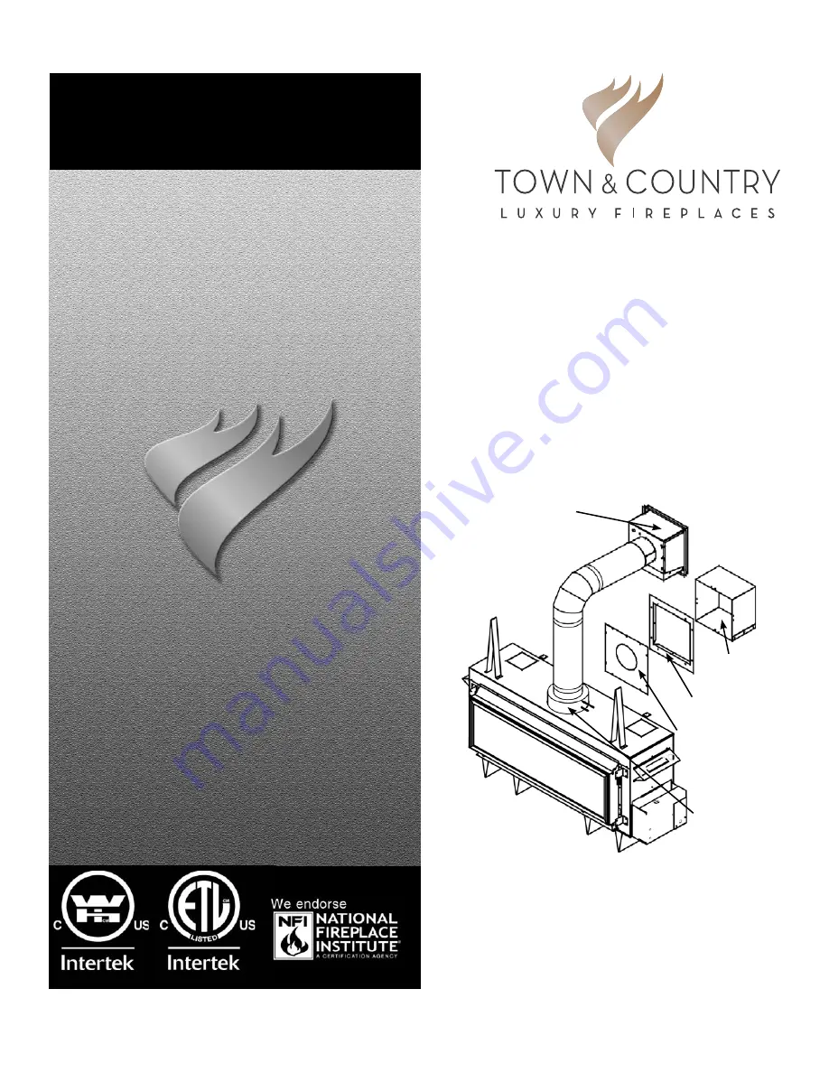
Vent Assy. 

Vent Adaptor

Wall Sleeve 
Assembly

Wall Pipe Cover

Inner Wall Plate

For use with 
any TC  Series 
“C” unit, 
except TC54.

IMPORTANT:
THESE INSTRUCTIONS ARE TO REMAIN 
WITH THE  HOMEOWNER

These instructions are supplementary to the Installation 

and Operating Instructions supplied with the fi replace 

and should be kept together. Refer to the  Installation 

and Operating Instructions for proper gas supply, safety 

requirements and operating instructions.

Summary of Contents for TCVT.FMPV3

Page 1: ...ve Assembly Wall Pipe Cover Inner Wall Plate For use with any TC Series C unit except TC54 IMPORTANT THESE INSTRUCTIONS ARE TO REMAIN WITH THE HOMEOWNER These instructions are supplementary to the Installation and Operating Instructions supplied with the fireplace and should be kept together Refer to the Installation and Operating Instructions for proper gas supply safety requirements and operatin...

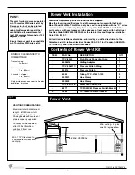
Page 2: ... 2 7 5093 02 Hose Clamp 2 8 TCVT 507156C Power Vent Switch Wire 1 9 8271 TCWS 54CE2 Pressure Switch Bracket 1 10 9280 TC Pressure Switch Bracket 1 MINIMUM CLEARANCES TO COMBUSTIBLE Terminal casing 0in 0mm Vertical vent pipe 1 5 in 38mm Horizontal vent pipe 1 5 in 38mm All other clearances are as per the fireplace installation instructions VENTING CONFIGURATIONS Maximum total horizontal vent length...

Page 3: ...nce to inside corner 3 inches 7 5 cm minimum H not to be installed above a meter regulator assembly within 3 feet 90 cm horizontally from the center line of the regula tor I clearance to service regulator vent outlet 6 feet 1 8 m minimum J clearance to nonmechanical air supply inlet to building or the combustion air inlet to any other appliance 12 inches 30 cm minimum K clearance to a mechanical a...

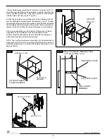
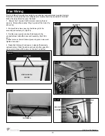
Page 4: ...te the power vent termination following the clearance to combustible table Page 2 venting configuration diagram Fig 1 2 and terminal location diagram Fig 3 4 Cut and frame a 14 1 2 wide by 14 3 4 high opening For standard up and out installations the opening should be 3 4 lower than the minimum specified in Fig 2 Height of the opening will vary with each installation See Fig 5 5 Attach the power v...

Page 5: ...onandthe number of elbows must not exceed specifications in Fig 1 and Fig 2 Fig 5 Fig 7 Fig 6 5 TERMINAL SECURING FLANGE WALL FINISH NO DEEPER THAN 1 1 4 EXHAUST 14 3 4 14 1 2 INNER WALL PLATE SEAL WITH SILICONE ON ALL FOUR SIDES 7 7 8 NOTCH AT THE TOP ...

Page 6: ...pe and attach pipe to the fireplace Fig 11 Connect the vent pipe to the vent terminal and then secure the inner wall plate and wall pipe cover to the framing This ensures that any insulation is retained in the wall and that the correct clearances are maintained 9 Run the required Simpson Duravent GS Secure Vent Selkirk Direct temp or ICC Exceldirect pipe from the adaptor to the terminal assembly A...

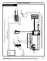
Page 7: ... module and in the orange wire running from the module to the socket labelled pilot on the valve Fig 13 and 14 4 Using the jumper wires provided connect the 120V hot supplywiretooneoftheblackwiresfromthecontrolmodule Then connect the hot wire from the power vent blower to the other black wire on the control module Fig 15 The module acts as a switch to turn on the power vent blower Also see wiring ...

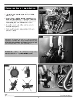
Page 8: ...Fig 17 3 Secure the pressure switch in the control box using the screw provided Fig 18 4 Continue with installation and reassemble all of the parts previously removed WARNING Thisswitchmustbeinstalledinaverticalposition and will not function if installed otherwise Fig 16 This power vent system can only run on 115 V AC Before operating the unit the battery backup located behind the wall switch rece...

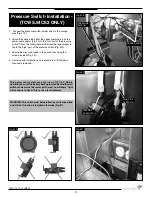
Page 9: ...he screw provided Fig 21 4 Continue with installation and reassemble all of the parts previously removed PRESSURE SWITCH LOW SIDE OF SWITCH HIGH SIDE OF SWITCH WARNING Thisswitchmustbeinstalledinaverticalposition and will not function if installed otherwise Fig 21 ORANGE WIRE Fig 19 Fig 20 Fig 21 Fig 22 This power vent system can only run on 115 V AC Before operating the unit the battery backup lo...

Page 10: ...ews securing the blower grill to the assembly and remove grill Fig 25 3 Run the power supply wire from the fireplace to the connector block inside the power vent assembly Fig 26 27 Connect wires as shwon Connect ground to ground screw and tightne strain relief 4 Reposition blower grill and secure in place with previously removed screws Place the end cover back onto the upper tabs and secure in pla...

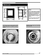
Page 11: ... withstand temperatures of at least 250 degrees fahrenheit or 120 degrees Celcius Ensure the your paint is compatible with Thurmalox 230 Series paint NOTE If this powervent is to be installed in a TC30 then it should use the full restrictor as shown in Fig 28 NOTE For all other units use the restrictor shown in Fig 29 Fig 28 Fig 29 16 1 8 16 11 16 8 3 4 7 7 8 6 11 16 14 11 16 1 5 16 11 Dimensions ...

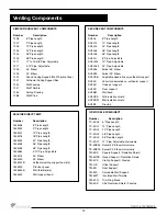
Page 12: ...sal support SV5SD Floor support SV5BM Wall band SV5RSA Attic radiation shield SV5RSM Wall radiation shield SV5BF Firestop SELKIRK DIRECT TEMP Number Description 1605006 6 Pipe Length 1605009 9 Pipe Length 1605012 12 Pipe Length 1605018 18 Pipe Length 1605024 24 Pipe Length 1605036 36 Pipe Length 1605048 48 Pipe Length 1605082 4 10 Pipe Adjustable 1605215 45 Elbow 1605230 90 Elbow 1605424B Cathedra...

Page 13: ...tor 1 4 Female Connector 1 4 Female Connector 1 4 Female Connector 1 4 Female Connector Wiring the Optional Power Vent Kit provided by Town Country Communication wires Main Pilot Low pressure side Orange Orange Pressure switch wire Supplied Power Vent switch wire Supplied Black Black STANDARD AWG 14 2 WIRE OR EQUIVALENT NOT SUPPLIED 111011 16 TCVT FMPV3 All electrical installations should be perfo...

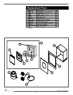
Page 14: ...5 8020 5 INNER WALL PLATE 1 6 5096 816 VENTING ADAPTER 1 7 TCVT 9280 PRESSURE SWITCH ASSEMBLY 1 8 TCVT 507156C POWER VENT SWITCH WIRE 1 9 5068 8065 1 4 LDF PAPER GASKET 1 10 TCVT 8035 TCVT FMPV OUTER CASING ASSEMBLY 1 11 5024 63 BLOWER POWERVENT 1 12 TCVT 80285WLD WALL SLEEVE ASSEMBLY 1 13 8029 WALL PIPE COVER 1 NOT SHOWN 6 8 3 1 13 5 12 10 9 11 2 4 14 Replacement Parts ...

Page 15: ...111011 16 TCVT FMPV3 15 ...

Page 16: ...TECHNICAL SUPPORT 250 748 1184 www townandcountryfireplaces net 2975 Allenby Rd Duncan BC V9L 6V8 Printed in Canada ...

Reviews: