background image


SERVICE MANUAL 


Embroidery Machine 

ESP9000   

(15    needles)   


Summary of Contents for ESP9000

Page 1: ...SERVICE MANUAL Embroidery Machine ESP9000 15 needles...

Page 2: ......

Page 3: ...ery machine in reference to this Service Manual refer to TROUBLESHOOTING first Then refer to ADJUSTMENT or REPLACEMENT as suggested 3 Only the critical instructions are given When a component must be...

Page 4: ...ed to be replaced use only parts certified by Aishin Seiki Co Ltd to ensure machine performance 2 To prevent any accident from occurring be sure to turn the power OFF before repair CONTENTS SPECIFICAT...

Page 5: ...n error message is displayed Check X MOTOR 4 2 4 An error message is displayed Check Y MOTOR 5 2 5 An error message is displayed NEEDLE CASE ERROR 6 2 6 Holder does not return to stroke center after h...

Page 6: ...s 1 3 2 12 Thread wiper hook does not operate 14 2 13 Thread trimming fails 15 2 14 Puckering 16 2 15 Improper tension 17 2 16 Jump function does not work 18 2 17 An error message is displayed THREAD...

Page 7: ...ook 21 3 2 Position of the hook support 23 3 3 Standby position of thread catcher 24 3 4 Blade pressure 25 3 5 Picker position 2 7 3 6 Position of the thread wiper hook 28 3 7 Adjustment of the jump m...

Page 8: ...C 30 3 9 Tension of deceleration belts B D E 31 3 10 Limit sensor 32 3 11 Thread sensor 3 4 3 12 Power box 35 36 4 1 Rotary hook 36 4 2 Thread...

Page 9: ...cutter 3 7 4 3 Thread catcher 3 8 4 4 Needle bar 39 4 5 Needle bar reciprocator 41 4 6 Thread change motor 43 4 7 Power supply board 44 4 8 Power circuit board 45 4 9 Jump motor 46 4 10 Main circuit...

Page 10: ...4 11 Operation box assembly 48 4 12 Upper shaft sensor 49 4 13 Sewing machine motor 50 4 14 X motor 51 4 15 Y motor 52 4 16 Thread wiper motor 53 4 17 Thread sensor 54 4 18 Operation control circuit...

Page 11: ...p lever return spring on the jump lever holder and pull down the spring as low as possible so that the spring will not be located on the jump positioning collar Fig 4 3 Tighten the setting screw c and...

Page 12: ...case cover upper upwards disconnect the connector CN2 and remove the case cover upper Fig 2 4 Disconnect all the connectors Fig 3 5 Remove two setting screws e and remove the main circuit board by hol...

Page 13: ...FIG 3 48...

Page 14: ...n box cover Fig 1 3 Remove four retaining screws d Unplug the cord and remove the operation box Fig 2 Installation 1 Plug in the cord 2 Secure the operation box to the bracket with four retaining scre...

Page 15: ...g screws d Fig 3 2 Insert the connector of the upper shaft sensor in CN3 on the main circuit board Fig 5 3 Fix the upper shaft sensor set with two setting screws c in the position where the center of...

Page 16: ...et surfaces of the sewing machine motor shaft and two setting screws c of the lower shaft joint are aligned and insert the sewing machine motor 2 Fix the sewing machine motor with four setting screws...

Page 17: ...d Lower shat joint 1 Mount the X motor to the motor base with four setting screws d Fig 2 Sewing machine motor c 2 Set the X motor gear to the belt and temporarily secure the motor base to the X base...

Page 18: ...e four set screws a and the base cover rear R Fig 1 2 Remove two setting screws b and the fan set Fig 2 3 Remove the Y pulley box adjusting screw c and nut d and loosen setting screw e and nut f Fig 2...

Page 19: ...rarily secure them with two setting screws g Fig 3 3 Adjust the belt tension with setting screw e and then firmly tighten with two setting screws g and nut f Fig 3 Note Check the tension after tightin...

Page 20: ...hat is contained in each setting screws of 3 and 4 sections Y motor bracket h Installation Y motor 1 Attached in the reverse procedure of removal Note Set the vertical position of the upper thread hoo...

Page 21: ...FIG 1 FIG 2 Motor base Upper thread hook lever f d e Thread wiper motor base c FIG 3 b Thread wiper hook base Connecting rod plate 56...

Page 22: ...the setting screw c Fig 4 2 Put the code of thread sensor base upwards into the thread sensor rail Fig 3 3 Putting a sensor arm into the slot of the thread sensor base and secure it with two setting s...

Page 23: ...ng screws c and disconnect connectors CN12 and CN7 then remove the case cover upper Fig 2 3 3 Remove the two setting screws d and the resin spacers then remove the console board Fig 4 Installation Att...

Page 24: ...FIG 4 59...

Page 25: ...motor drive 10 Thread wiper Motor drive sliding type with thread retaining mechanism 11 Picker method Picking at start end of sewing and cutting thread 12 Stitch speed 1 200spm maximum 800spm standard...

Page 26: ...22 Power supply and consumption 100 120 200 240VAC 50 60Hz 220W 23 Dimensions 835 H x 745 W x 740 D 2...

Page 27: ...power supply does not turn on Preliminary inspection Power cord may be unplugged AC power cord Cable from the power box to the embroidery machine may be disconnected DC power cord Power box Main circu...

Page 28: ...e P 44 Connection of connector CN 12 Must be connecte d correctly Connect the cable correctly or replace the main circuit board See 47 P Connection of connector CN 7 Must be connecte d correctly Conne...

Page 29: ...ust be connecte d correctly Connect correctly Resistance Check connector visually Disconnect the power connector and check the resistance between and and and with a circuit tester 0 2 to 0 6 Replace S...

Page 30: ...Connection of connector CN 3 Must be connecte d correctly Connect the cable correctly or replace the main the circuit board See P 47 CN3 5...

Page 31: ...f power and sensor connectors Must be connecte d correctly Connect correctly Resistance Disconnect the power connector and check the resistance between and and and with a circuit tester 0 4 to 0 8 Rep...

Page 32: ...Take out the fuse and check it visually 125V 20 A Must be in good condition Replace the fuse Connection of connectors CN 1 CN7 Must be connecte d correctly Connect correctly or replace See P 47 CN1 C...

Page 33: ...ion of power and sensor connectors Must be connecte d correctly Connect correctly Resistance Disconnect the power connector and check the resistance between and and and with a circuit tester 0 2 to 0...

Page 34: ...Take out the fuse and check it visually 125V 20 A Must be in good condition Replace the fuse Connection of connectors CN 4 CN 6 Must be connecte d correctly Connect correctly or replace See P 47 CN4 C...

Page 35: ...to 6 0 Replace See P 43 Connection ofconnectors CN3 CN4 Remove the cover of the joint circuit board and check visually Must be connected correctly Connect correctly or replace Connection ofconnector...

Page 36: ...Connection of connector CN 10 Must be connected correctly Replace See P 47 CN10 11...

Page 37: ...istances Y set the X holder to its forefrontpositionbypressingtheemergency stop button and check the distances from thesurfaceofthedetectingplatetothecenter ofthephoto sensor X 65 7 1mm Y 213 5 1mm Po...

Page 38: ...th a circuit ester t X motor Across GND red and black and U yellow U yellow and black V V white white and black W brown W brownand black A orange A orange and black k B pink and black B pin y motor o...

Page 39: ...p damage Pushtheguidepin downasfarasit willgointhe directionofthe arrowand checkthe returning movementof thepin No damage is identified on the hook tip Repair Clearance between the picker and the bobb...

Page 40: ...Picker height C 7 9 mm when piker solenoid is ON Adjust See P 27 15...

Page 41: ...ncorrect Cloth tension may be too weak Needle size may be incorrect for the thread Needles and rotary hook Item Method Standard Action Needle and rotary hook timing A 201 3 Standar d 1 8 to 3 1mm Adju...

Page 42: ...ndard Action Rouge edges or burrs on thread path Free of rough edges or burrs Smooth edges with emery paper 800 or replace tough parts Rouge edges in needle plate hole Free of rouge edges Repair or re...

Page 43: ...P 21 Rouge edges on hook support Free of rouge edges Repair or replace See 23 P Clearance under the rotary hook support A 0 5 to 0 8mm Adjust See P 23 Relative positions of the center of the protrusi...

Page 44: ...andard Action Burred edges on hold in the needle plate Free of burrs Repair or replace the needle plate Burred edges on the rotary hook Free of burrs Repair or replace the rotary hook See P 36 Burred...

Page 45: ...n may be incorrect Item Method Standard Action Needle to rotary hook clearance A 0 1 to 0 3mm Adjust See P 21 Needle bat height B 201 3 Standar d 1 8to 1mm 3 Adjust See P 21 Needle lift D C 8 0 0 1mm...

Page 46: ...hook return Push the guide pin down as far as it will go in the direction of the arrow and check the returning movement of the pin Must return smoothly Adjustme nt is performe d by loosenin g a guide...

Page 47: ...st See P 28 Connection of power connector Must be connecte d correctly Connect correctly Resistance Disconnect the power connector and check the resistance between and and and and with a circuit teste...

Page 48: ...lever and stopper At this point LED must be turned on A 0 5m m Adjust See P 24 Flaw on the thread catcher Free of flaws Repair or replace Fitted position of the thread catcher Check the position of t...

Page 49: ...he needle plate may be burred The needle thread may be stuck around the threading tube holder and the thread take up lever Item Method Standard Action Thread take up spring stroke A Hold the thread be...

Page 50: ...ions of the center of the protrusion on the hook support and the center of the needle Check protrusion on hook support visually B 0 0 2mm Adjust See P 23 2 TROUBLESHOOTING The thread tension may be to...

Page 51: ...imately 1mm B 5 1g The screw of the retracting lever aligned with the ratchet mark Clearance under the rotary hook support A 0 5 to 0 8mm Relative positions of the center of the protrusion on the hook...

Page 52: ...5 0 1mm Must be connecte d correctly 4 8 6 0 Adjust See P 29 Connect correctly Replace See P 47 Wrong movement or damage of needle bar reciprocato r Free of burrs Replace See P 41 Connection of connec...

Page 53: ...Standard Action Torque of rotary tension disk Must turn smoothly Check position of sensor A less than 0 8mm Adjust See P 34 Connection of connector CN 1 Remove the cover of joint circuit board and che...

Page 54: ...Connection of connector CN 7 Check the connector visually Must be connecte d correctly Replace See P 45 CN7 22...

Page 55: ...able The embroidery frame may be interfering The embroidery frame screws may be loose Item Method Standard Action Belt A F 0 46 G 10 8 2 16mm Belt B F 0 46 G 0 9 0 18mm Belt C F 0 95 G 7 4 1 48mm Belt...

Page 56: ...gency stop button and check the voltage of the sections below with a circuit tester X motor Across 5V red and GND red and black Y motor Across 5V red and GND red and black 5V when turned on Replace Se...

Page 57: ...loosen the rotary hook set screw a closest to the hook tip and loosen the other two set screws Fig 2 2 Rotate the hand wheel anti clockwise to move the needle bar to the bottom dead center 180 Rotate...

Page 58: ...FIG 2 FIG 3 201 3 0 1 0 3 mm 22...

Page 59: ...ove the lower cover Fig 2 2 Loosen the set screw of the needle bar connecting stud set the needle bar height gauge adjust the height and tighten the screw Figs 3 4 Note Change the needle to check the...

Page 60: ...FIG 2 FIG 3 FIG 4 Needle bar Stopper Needle bar Connecting stud Needle bar Needle bar height gauge Needle plate bracket 24...

Page 61: ...must not exceed 0 2mm Fig 1 Adjustment 1 Loosen the two set screws a 2 Move the hook support in direction C or D to adjust the clearance between the hook support to the rotary hook Fig 2 3 Move the h...

Page 62: ...4 4 If the LED is not turned on loosen the set screw d of the thread trimming drive lever and adjust the clearance between the lever and stopper to 0 5mm Fig 2 Then perform the thread trimming to che...

Page 63: ...FIG 4 e Drive arm FIG 5 27...

Page 64: ...thread trimming lever and smear the thread catcher with a felt pen Fig 2 5 Perform trimming manually and check that the felt pen marking on the thread catcher is scraped evenly even contact 6 Perform...

Page 65: ...set screws a Fig 5 2 While steadying the thread cutter by hand turn adjusting screw b in direction C just so the screw tip barely touches the thread cutter Fig 5 3 While steadying the thread cutter by...

Page 66: ...oosen two set screws c and the set screws a adjust the position of the picker by sliding the picker solenoid base back and forth After adjusting tighten the set screw a then move the picker base to th...

Page 67: ...screws a to move the thread presser base in the direction of the arrow Position the base where the guide pin moves smoothly and tighten four set screws a Fig 3 2 If distance A from the needle center t...

Page 68: ...IG 1 FIG 2 FIG 3 3 7 Adjustment of the Jump motor position Inspection 1 Remove the needle case Refer to 4 5 Replacement of needle bar reciprocator 3 ADJUSTMENT Guide pin B b Thread wiper motor base 32...

Page 69: ...5mm Fig 2 Adjustment 1 Loose the two set screws c and adjust the jump motor position by moving the jump motor right left Fig 3 refer to 4 Replacement of needle bar reciprocator 2 After adjusting locat...

Page 70: ...FIG 3 34...

Page 71: ...loosen the rotary hook set screw a closest to the hook tip and loosen the other two set screws Fig 2 2 Rotate the hand wheel anti clockwise to move the needle bar to the bottom dead center 180 Rotate...

Page 72: ...FIG 2 FIG 3 201 3 0 1 0 3 mm 22...

Page 73: ...cover Fig 2 2 Bring the needle bar to the bottom dead center loosen the set screw of the needle bar connecting stud and set the needle bar height then tighten the screw Figs 1 3 Note Change the needle...

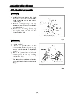
Page 74: ...FIG 2 FIG 3 Needle bar Stopper Needle bar Connecting stud 24...

Page 75: ...not exceed 0 2mm Fig 1 Adjustment 1 Loosen the two setting screws a 2 Move the hook support in direction C or D to adjust the clearance between the hook support to the rotary hook Fig 2 3 Move the hoo...

Page 76: ...If the LED is not turned on loosen the set screw d of the thread trimming drive lever and adjust the clearance between the lever and stopper to 0 5mm Fig 2 Then perform the thread trimming to check th...

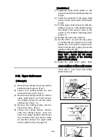
Page 77: ...FIG 4 e Drive arm FIG 5 27...

Page 78: ...thread trimming lever and smear the thread catcher with a felt pen Fig 2 5 Perform trimming manually and check that the felt pen marking on the thread catcher is scraped evenly even contact 6 Perform...

Page 79: ...o setting screws a Fig 5 2 While steadying the thread cutter by hand turn adjusting screw b in direction C just so the screw tip barely touches the thread cutter Fig 5 3 While steadying the thread cut...

Page 80: ...Note Incase the picker solenoid is exchanged Loosen two set screws c and the set screws a adjust the position of the picker by sliding the picker solenoid base back and forth After adjusting tighten t...

Page 81: ...ing screws a to move the thread presser base in the direction of the arrow Position the base where the guide pin moves smoothly and tighten four setting screws a Fig 3 2 If distance A from the needle...

Page 82: ...e case Refer to 4 5 Needle bar reciprocator on page 41 2 Remove three setting screws a two set screws b and remove the arm front cover L Fig 1 3 In this state the clearance between the jump lever and...

Page 83: ...jump motor right left Fig 3 refer to 4 5 Needle bar reciprocator on page 41 2 After adjusting locate the jump motor at its highest position and tighten two setting screws 3 Install the arm front cove...

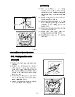
Page 84: ...FIG 3 34...

Page 85: ...8 2 16mm Fig 2 6 When applying a force of 0 95kg to drive belt C amount of deflection G must be 7 4 1 48mm Fig 2 Adjustment 1 If amount of deflection G of drive belt A differs from that specified loo...

Page 86: ...FIG 4 31...

Page 87: ...lection of deceleration belt B differs from that specified loosen the nut and two set screws d and turn setting screw e in the direction of the arrow After adjustment tighten two set screws d and the...

Page 88: ...FIG 4 33...

Page 89: ...t home position return Note Press the SET key 7 Check the distance X from the right most surface of the detecting plate to the center of left side X limit sensor shown in Fig 2 8 Move the X axis drive...

Page 90: ...FIG 2 35...

Page 91: ...t Fig 2 Note The slit is placed in the center of the sensor slot Fig 2 3 If the Y distance differs from that specified loosen two setting screws c and move the limit sensor to the specified position t...

Page 92: ...ate should be located at the position where the distance A between the center of the disk and the center of the sensor is less than 0 8mm Fig 2 Adjustment 1 If the distance differs from that specified...

Page 93: ...2 a Sensor arm 3 38...

Page 94: ...and check that the voltage across and is 24 0 24 5V Fig 2 Adjustment 1 Remove eight setting screws a and then the case cover Fig 3 2 Turn power on 3 If the 24V power supply differs from that specifie...

Page 95: ...FIG 3 FIG 4 VR6 Power supply board 40...

Page 96: ...ottom dead center Rotate the hand wheel further until LCD display shows the needle position at 201 3 Fig 2 5 Rotate the rotary hook manually to align the hook tip with the needle center Secure a clear...

Page 97: ...FIG 3 FIG 4 0 5 to 0 8mm 0 2mm or less Hook support hook support 37...

Page 98: ...n parallel with the needle plate bracket A B and fix it in that position with two setting screws b Fig 2 Inspection After setting the thread cutter check again that the thread catcher makes an initial...

Page 99: ...ng screw b Fig 2 Inspection 1 When the thread catcher is in the standby position the dimension between the shoulder and the thread cutter must be 0 0 5mm Fig 3 Please refer to 3 3 standby position of...

Page 100: ...FIG 4 40...

Page 101: ...d remove two setting screws d and the sensor arm Fig 3 7 Remove two setting screws e and the tension base set Fig 3 8 Loosen the set screw f and remove the needle needle clamp and cushion ring A Fig 4...

Page 102: ...3 mm then tighten the setting screw d in the right direction Figs 1 2 g Needle bar holder spring Washer 7 Adjust the distance from the lower end of the top dead center stopper to the upper end of the...

Page 103: ...FIG 2 Needle bar c Top dead center stopper needle bar connecting stud FIG 3 43...

Page 104: ...ey in the test mode of LCD locate the cursor at No 2 and press SET key 10 Select the No 15 of a needle number by color change key 11 Turn the hand wheel until the angle of LCD displays 107 5 12 Remove...

Page 105: ...FIG 5 45...

Page 106: ...ide rail set the needle case to the right most stopper of the case linear and fix by pushing from the top Fig 4 6 Check the needle position at the needle No 15 Note No play with the needle case Note I...

Page 107: ...tting screws g and the thread change motor Fig 4 Installation 1 Install the thread change motor and the hand wheel B with setting screws 2 Install the thread change motor base with two each set screws...

Page 108: ...it board Fig 2 3 Remove four setting screws b and remove the power supply board Fig 2 Installation 1 Install the power supply board with four setting screws b Fig 2 2 Connects the connector and connec...

Page 109: ...each four set screws c and the base cover rear R Fig 1 4 Loosen two setting screws d remove other two setting screws e and move the case cover upper Fig 3 5 Remove the connector CN9 of the computer b...

Page 110: ...FIG 1 FIG 2 FIG 3 c Base cover rear R Table set a FIG 4 Rear cover b b e d Case cover upper Power circuit board f 50...

Page 111: ...Printed in Japan 2002 8...

Reviews: