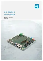
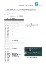
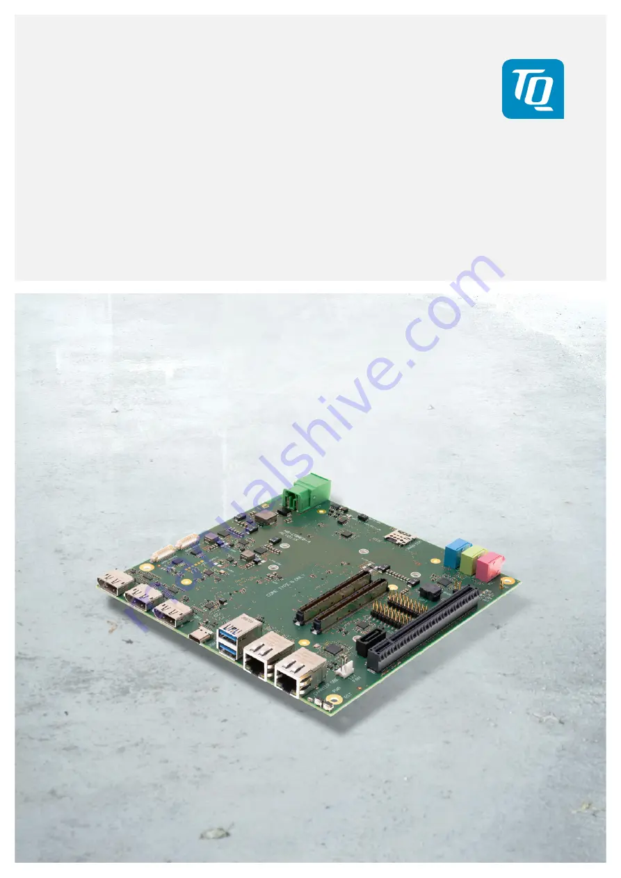
background image


User's Manual  l  MB-COME6-4 UM 0100  l  © 2022, TQ-Systems GmbH 


Page  i 


MB-COME6-4 
User's Manual 

 
MB-COME6-4 UM 0100 
15.03.2022 

Summary of Contents for MB-COME6-4

Page 1: ...User s Manual l MB COME6 4 UM 0100 l 2022 TQ Systems GmbH Page i MB COME6 4 User s Manual MB COME6 4 UM 0100 15 03 2022 ...

Page 2: ...ces 8 3 5 1 Power Supply 10 3 5 2 DisplayPort 10 3 5 3 USB Host Interfaces 11 3 5 4 Gigabit Ethernet 11 3 5 5 Serial Interface RS 232 12 3 5 6 Embedded Display Port 13 3 5 7 LVDS 14 3 5 8 M 2 socket with M Key for PCIe SSD devices 15 3 5 9 M 2 socket with M Key for PCIe SSD devices 15 3 5 10 M 2 socket with B Key for WWAN modules or SATA SSD devices 15 3 5 11 M 2 socket with E Key for I O devices ...

Page 3: ...nector X20 17 Table 12 I2 C and COME Signal Connector X21 17 Table 13 Debug LEDs 18 Table 14 Labels on MB COME6 4 20 Table 15 I2 C Address Mapping 21 Table 16 Acronyms 24 Table 17 Further Applicable Documents and Links 26 FIGURE DIRECTORY Figure 1 MB COME6 4 Block Diagram 6 Figure 2 MB COME6 4 Top view 8 Figure 3 MB COME6 4 Bottom view 9 Figure 4 RJ45 Connectors 11 Figure 5 10 pin RS232 Connector ...

Page 4: ...brand and trademarks are rightly protected by a third party 1 3 Disclaimer TQ Systems GmbH does not guarantee that the information in this User s Manual is up to date correct complete or of good quality Nor does TQ Systems GmbH assume guarantee for further usage of the information Liability claims against TQ Systems GmbH referring to material or non material related damages caused due to usage or ...

Page 5: ...sed This symbol represents important details or aspects for working with TQ products Command A font with fixed width denotes commands contents file names or menu items 1 8 Handling and ESD Tips General handling of your TQ products The TQ product may only be used and serviced by certified personnel who have taken note of the information the safety regulations in this document and all related rules ...

Page 6: ...ents used for example CompactFlash cards are to be taken note of They contain if applicable additional information that must be taken note of for safe and reliable operation These documents are stored at TQ Systems GmbH Chip errata It is the user s responsibility to make sure all errata published by the manufacturer of each component are taken note of The manufacturer s advice should be followed S...

Page 7: ...durability and long term availability 2 1 Functional Overview The following key functions are implemented on the MB COME6 4 Supported Modules COM Express Compact Basic Modules with Type 6 pinout COM 0 R3 0 External Interfaces 2 x 2 5 Gigabit Ethernet 2 x USB 3 2 Gen 2 Type A connector with USB 3 0 compatibility 1 x USB 3 2 Gen 2 Type C connector with USB 3 0 compatibility 3 x DisplayPort DP connec...

Page 8: ...Express Type 6 pinout Carrier full featured Other configurations are available on request 2 4 Accessories DK USB TYPA MOL5 Adapter cable from internal USB connector to A Type receptacle 150 mm long DK RS232 9POL DSUB PICOBLADE Adapter cable from internal connector to 9 pin D Sub male connector 150 mm long Battery CR2032 lithium coin cell Meanwell 180W 12V Power Supply GST220A12 R7B Please contact ...

Page 9: ...User s Manual l MB COME6 4 UM 0100 l 2022 TQ Systems GmbH Page 6 3 FUNCTION 3 1 Block Diagram The following illustration shows the block diagram of the MB COME6 4 Figure 1 MB COME6 4 Block Diagram ...

Page 10: ...se no mass storage device no Ethernet cable etc connected Note Power requirement The MB COME6 4 input current is not fused The user has to ensure that the input current does not exceed the maximum current of 25 A 300 W Additionally the power supply must be configured with enough reserve It should be calculated with the maximum power consumption of all connected components 3 3 Environmental Specifi...

Page 11: ...Switch for LVDS eDP or ESPI LPC X3 X4 X5 Display Port X7 2 USB 3 0 X26 12 V Fan X18 SPI flash socket X22 SATA socket X1 COM Express connector Row A B Debug LEDs X23 X24 RS232 connector X2 COM Express connector Row C D X12 blue Line in X13 green Headphone out X14 pink Mic in S1 Reset Button X20 X21 Debug socket X19 PCIe Card slot PEG port X6 USB Type C X11 SIM Card socket for WWAN cards on M 2 B Ke...

Page 12: ... GmbH Page 9 Figure 3 MB COME6 4 Bottom view X45 X46 X47 USB 2 0 X42 M 2 socket E Key X44 M 2 socket M Key for SSDs X40 M 2 socket B Key for WWAN or SSD X38 Embedded DisplayPort X27 LVDS X39 Display Backlight X43 RTC battery X41 M 2 socket M Key for SSDs ...

Page 13: ... supported from power supply 2 GND Note Power requirement The MB COME6 4 input current is not fused The user has to ensure that the input current does not exceed the maximum current of 25 A 300 W Additionally the cable diameter has to be selected in correlation to the maximum current The mainboard power design is optimized for the new high performance TQMx110EB COM Express module This module can d...

Page 14: ... Molex 53398 0571 Mating connector Molex 51021 0500 crimp housing Table 3 USB 2 0 Host Extension Connectors Pin Signal Cable Colour 1 5 V Red 2 D White 3 D Green 4 GND Black 5 GND 3 5 4 Gigabit Ethernet The MB COME6 4 supports two 2 5 Gigabit Ethernet ports The Ethernet signals of the COM Express connector are routed to the X8 left connector The MB COME6 4 provides an Intel i225 Ethernet controlle...

Page 15: ...TS 3 3 V output not available The four COM Express serial signals RX TX are specified to provide a protection and level shifter circuit The implementation of this circuit would result in a lower transfer speed on the two serial ports of the COM Express module On the MB COME6 4 the protection circuit is removed and the serial ports provide a transfer rate of up to 115 kbaud The MB COME6 4 can only ...

Page 16: ...or type JAE HD1S040HA1 Mating connector JAE HD1P040MA1 Table 7 eDP Connector Figure 6 eDP Connector Figure 7 Config Switch eDP LVDS Pin Signal Remark 1 NC 2 GND 3 TX3 Lane 3 differential pair 4 TX3 5 GND 6 TX2 Lane 2 differential pair 7 TX2 8 GND 9 TX1 Lane 1 differential pair 10 TX1 11 GND 12 TX0 Lane 0 differential pair 13 TX0 14 GND 15 AUX AUX channel 16 AUX 17 GND 18 3V3 3 3 V supply voltage 1...

Page 17: ...er If the programmer supports 3 3 V output voltage the MB COME6 4 can be programmed without any additional power supply In this case no COM Express module should be connected to the carrier board X27 LVDS connector Connector type Hirose DF19G 30P 1H Mating connector Hirose DF19 30S 1C Table 8 LVDS Connector Figure 8 LVDS Connector Pin Signal Remark 1 A0 Odd bus 2 A0 Odd bus 3 A1 Odd bus 4 A1 Odd b...

Page 18: ... Express module and the connected device Please contact support tq group com for further information about suitable M 2 SSDs 3 5 10 M 2 socket with B Key for WWAN modules or SATA SSD devices The MB COME6 4 provides a socket to support SATA based M 2 SSDs with 22 mm width and 80 mm length or modules with 22 mm width and 42 mm length 1x USB 2 0 and SATA signals are routed to this socket For mounting...

Page 19: ... for 12 V fans X26 12 V fan connector Connector type Tyco 640456 3 Mating connector 3 pin fan connector 2 54 mm pitch Table 10 Fan Connector Figure 11 Fan Connector 3 5 15 PCI Express Connector The MB COME6 4 provides a standard PCI Express x16 slot connector The PCI Express port can be used for PCI Express graphics devices or high speed non graphic PCI Express devices e g quad Gigabit Ethernet or...

Page 20: ...put 8 GPO1 Output 9 GPI2 Input 10 GPO2 Output 11 GPI3 Input 12 GPO3 Output 13 SMB_CK SM bus clock 14 SUS_S3 Suspend to RAM 15 SMB_DAT SM bus data 16 SUS_S4 Suspend to disk 17 SMB_ALERT SM bus alert 18 SUS_S5 Soft off 19 BATLOW Battery low signal 20 COME_WDT Come Watchdog Timer Pin Signal Remark 1 V_5V_STBY 5 V supply 2 GND 3 V_5V_STBY 5 V supply 4 GND 5 PWR_BTN Power Button 6 GND 7 RST_BTN Power B...

Page 21: ...purposes SPI Flashes with SO8W package can be inserted If the BIOS_DIS1 jumper is set the BIOS from the SPI flash in the socket is active Figure 13 SPI socket and BIOS_DIS1 Jumper 3 5 19 COM Express Connector The EPT 401 55103 51 or equivalent is used as COM Express connector The stack height board to board distance between carrier board and module is 8 mm 3 6 Buttons 3 6 1 Reset Button The MB COM...

Page 22: ... 170 mm The following illustration shows the dimensions of the MB COME6 4 Figure 14 MB COME6 4 Dimensions Please contact support tq group com for more details about 2D 3D Step models 4 2 Protection Against External Effects The MB COME6 4 is not protected against dust external impact and contact IP00 Adequate protection has to be guaranteed by the surrounding system ...

Page 23: ...mbH Page 20 4 3 Labeling Figure 15 Position of labels The labels on the MB COME6 4 show the following information Table 14 Labels on MB COME6 4 Label Content AK1 Serial number AK2 MB COME6 4 version and revision tests performed AK3 MAC address AK1 AK3 AK2 ...

Page 24: ...ME6 4 is routed to the PCIe card optional and to the feature connector On this bus no device is connected 5 2 Driver Download The MB COME6 4 module is well supported by the standard operating systems which already include most of the drivers required It is recommended to use the latest drivers for optimal performance and the full feature set of the module Drivers for the Intel i225 Gigabit Etherne...

Page 25: ...he soldering processes are RoHS compliant 6 5 WEEE The final distributor is responsible for compliance with the WEEE regulation Within the scope of the technical possibilities the MB COME6 4 was designed to be recyclable and easy to repair 6 6 REACH The EU chemical regulation 1907 2006 REACH regulation stands for registration evaluation certification and restriction of substances SVHC Substances o...

Page 26: ...ing PCB polychlorinated biphenyls are not used These points are an essential part of the following laws The law to encourage the circular flow economy and assurance of the environmentally acceptable removal of waste as at 27 9 94 source of information BGBl I 1994 2705 Regulation with respect to the utilization and proof of removal as at 1 9 96 source of information BGBl I 1996 1382 1997 2860 Regul...

Page 27: ...ad Only Memory EMC Electromagnetic Compatibility eSATA external Serial ATA ESD Electrostatic Discharge FAE Field Application Engineer FIFO First In First Out flexiCFG Flexible Configuration FPGA Field Programmable Gate Array FR 4 Flame Retardant 4 GND Ground GPIO General Purpose Input Output HD High Definition HD High Definition Audio HDA High Definition Audio HDD Hard Disk Drive HDMI High Definit...

Page 28: ...Restriction of the use of certain Hazardous Substances RS 232 Recommended Standard serial interface RTC Real Time Clock SATA Serial ATA SCU System Control Unit SD Secure Digital SD MMC Secure Digital Multimedia Card SDRAM Synchronous Dynamic Random Access Memory SIM Subscriber Identity Module SMB System Management Bus SO DIMM Small Outline Dual In Line Memory Module SPD Serial Presence Detect SPI ...

Page 29: ...able Documents and Links No Name Rev Date Company 1 PICMG COM0 COM Express Module Base Specification Rev 3 0 March 31 20217 PICMG 2 PICMG COM Express Carrier Design Guide available for public download https www picmg org wp content uploads PICMG_COMDG_2 0 RELEASED 2013 12 061 pdf Rev 2 0 Dec 6 2013 PICMG ...

Page 30: ...TQ Systems GmbH Mühlstraße 2 l Gut Delling l 82229 Seefeld info tq group com l www tq group com ...

Reviews: