
1
© 2013 Tractel Ltd. All Rights Reserved.
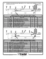
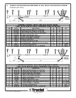
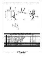
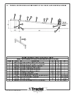
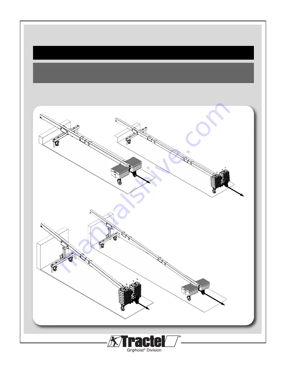
4’ reach light skybeam
®
1,000 lb. (454kg) capacity
United States:
Boston: 1 800 421-0246 • Los Angeles: 1 800 675-6727 • griphoist.usa@tractel.com
Canada:
Montreal: 1 800 561-3229 • Toronto: 1 800 561-3229 • griphoist.canada@tractel.com
temporary outrigger beam for suspended platforms
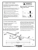
assembly manual for
Tractel, Griphoist
®
Division
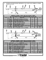
4’ Horizontal Beam
4’ Inclined Beam
Tieback
Required
Tieback
Required
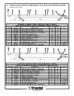
Tieback
Required
Tieback
Required


