background image

S

SA

AF

FE

ET

TY

Y W

WA

AR

RN

NIIN

NG

G

Only qualified personnel should install and service the equipment. The installation, starting up,
and servicing of heating, ventilating, and air-conditioning equipment can be hazardous and
requires specific knowledge and training. Improperly installed, adjusted or altered equipment
by an unqualified person could result in death or serious injury. When working on the
equipment, observe all precautions in the literature and on the tags, stickers, and labels that
are attached to the equipment.

June 2020

A

AC

CC

C--S

SV

VN

N2

22

22

2B

B--E

EN

N

Installation Guide

Duct Flange Kit

Odyssey Split System Air Handlers
5 to 25 Tons

B

BA

AY

YD

DU

UC

CT

T0

01

10

0A

A:

TWE051, TWE060,
TWE072, TWE076,
TWE090, TWE120
and TWE101
B

BA

AY

YD

DU

UC

CT

T0

01

11

1A

A:

TWE126, TWE150,
TWE156, TWE180,
TWE201, TWE240,
TWE251 and
TWE300

Summary of Contents for BAYDUCT010A

Page 1: ...y an unqualified person could result in death or serious injury When working on the equipment observe all precautions in the literature and on the tags stickers and labels that are attached to the equ...

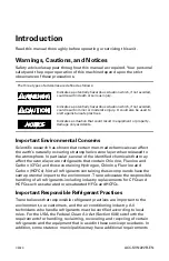
Page 2: ...g stratospheric ozone layer when released to the atmosphere In particular several of the identified chemicals that may affect the ozone layer are refrigerants that contain Chlorine Fluorine and Carbon...

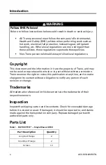
Page 3: ...T follow precautions in this manual and on the tags stickers and labels as well as the instructions below Before installing servicing this unit technicians MUST put on all PPE required for the work be...

Page 4: ...re the property of Trane and may not be used or reproduced in whole or in part without written permission Trane reserves the right to revise this publication at any time and to make changes to its con...

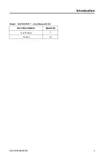
Page 5: ...ACC SVN222B EN 5 Table 2 BAYDUCT011 Dual Blower AH Kit Part Description Quantity Duct Flange 2 Screws 20 I In nt tr ro od du uc ct ti io on n...

Page 6: ...ews provided in the kit to secure the duct flanges to the air handler See drawing that follows Figure 1 TWE051 and TWE060 Single Blower Air Handler 16 1 4 412 8 24 1 16 611 2 DUCT FLANGE 1 25 4 HEIGHT...

Page 7: ...s provided in the kit to secure the duct flanges to the air handler See drawing that follows Figure 4 TWE126 TWE150 TWE156 and TWE180 Dual Blower Air Handler 16 5 16 414 3 54 15 16 1395 4 DUCT FLANGE...

Page 8: ...t trane com or americanstandardair com Trane and American Standard have a policy of continuous product and product data improvement and reserve the right to change design and specifications without no...

Reviews: