background image


AI1401 Reader User Guide

TransCore, Inc.

19111 Dallas Parkway, Suite 300

Dallas, Texas  75287-3106

October 2004

P/N 411064-002

Summary of Contents for AI1401

Page 1: ...AI1401 Reader User Guide TransCore Inc 19111 Dallas Parkway Suite 300 Dallas Texas 75287 3106 October 2004 P N 411064 002...

Page 2: ......

Page 3: ...are protected by one or more of the following U S patents 4 739 328 4 864 158 4 999 636 and foreign equivalent patents Other patents pending For further information contact TransCore 19111 Dallas Par...

Page 4: ...on manual Operating this equipment in a residential area is likely to cause harmful interference in which case depending on the laws in effect the users may be required to correct the interference at...

Page 5: ...Contents...

Page 6: ......

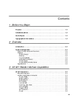
Page 7: ...obust Design 2 5 Memory 2 6 Tag Compatibility 2 6 Appended Information 2 6 Power Supply 2 6 Power Saving Standby Mode 2 6 Specifications 2 6 3 AI1401 Reader Interface Capabilities AI1401 Connectors 3...

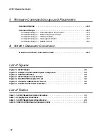
Page 8: ...onversion Table B 3 List of Figures Figure 2 1 AI1401 Reader 2 3 Figure 2 2 Example of AI1401 Reader System Configuration 2 4 Figure 2 3 ASCII RS 232C Port 2 4 Figure 3 1 AI1401 Reader Connector Panel...

Page 9: ...1 Before You Begin...

Page 10: ......

Page 11: ...ation found in this user guide Table 1 1 AI1401 Reader User Guide Information Chapter 1 Before You Begin Describes the purpose intended audience guide topics related documentation and document convent...

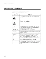
Page 12: ...s it appears on screen Function Start with the characters G4 and are in mixed case with no underscores and include parentheses after the name as in G4FunctionName Menu Item Appears on a menu Capitaliz...

Page 13: ...2 Overview...

Page 14: ......

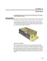
Page 15: ...e component of any portable reader system Figure 2 1 AI1401 Reader When interfaced with the antenna and power source the AI1401 Reader uses RF energy to read data from an electronic tag a field distur...

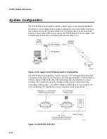
Page 16: ...ware for example RF modems Figure 2 2 Figure 2 2 Example of AI1401 Reader System Configuration The AI1401 Reader is designed to operate using a 13 2V rechargeable NiCad battery or equivalent DC power...

Page 17: ...second startup option When interfaced with the user s antenna and power source and depending upon how the reader is programmed the AI1401 Reader provides the following functions Transmits carrier freq...

Page 18: ...r uses a 13 2V rechargeable nickel cadmium NiCad battery not included or equivalent DC power source Power Saving Standby Mode When not in active use the AI1401 Reader turns off power to all circuitry...

Page 19: ...battery backed Data buffer capacity 1 000 tag reads of 128 bits with appended data Communications port RS 232C 110 to 19 200 Baud Other features Real time calendar clock Power saving algorithm 40 ms s...

Page 20: ...AI1401 Reader User Guide 2 8...

Page 21: ...3 AI1401 Reader Interface Capabilities...

Page 22: ......

Page 23: ...the location of the connectors Figure 3 1 identifies the connectors and their purposes Figure 3 1 AI1401 Reader Connector Panel RS 232C Interface The RS 232C interface connector is a standard DB9 sock...

Page 24: ...handheld computer via an RS 232C cable connection Figure 3 2 defines the pin positions of the RS 232C connector Figure 3 2 RS 232C DB9 Connector Pin out Auxiliary Input Output Connector The user s inp...

Page 25: ...inactivity from either the actuator switch or the RS 232C port The 10 second power off time out is a factory default value The user can change the time out to one minute using the 751 command Battery...

Page 26: ...or signal that turns on RF power RF Connector The user s I O interface actuator contains an antenna that broadcasts the RF signal generated by the RF module and retrieves the amplitude modulated retur...

Page 27: ...A Firmware Command Groups and Parameters...

Page 28: ......

Page 29: ...characters are sent to the AI1401 Reader they are automatically echoed back to the host As soon as the command is terminated with Enter or CR the AI1401 Reader responds to the command with one of the...

Page 30: ...bits parity and end of line delay using Command Group 1 commands Baud Rate Select 100x where x 0 to 6 0 110 baud 1 300 baud 2 1200 baud 3 2400 baud 4 4800 baud 5 9600 baud factory setting 6 19 2 K bau...

Page 31: ...communications will be at the new parity setting Command Group 2 Real Time Clock Control Group 2 commands control the real time clock which maintains the time and date The user can set or display the...

Page 32: ...shown with no spaces between characters Use for ward slashes as delimiters All entries use decimal characters 0 through 9 Response Done or Error Display Time and Date 22 Response hh mm ss dd MM DD YY...

Page 33: ...splayed data is som 20 chrs eom where som start of message character 20 chrs 20 data characters eom end of message character Response Done or Error Appends Time and Date to Data 302 The format of the...

Page 34: ...and not cleared from the data buffer Response Done or Error Disables Uniqueness Mode 306 The reader acquires and stores or sends to the RS 232C port the same tag ID when the user provided RF actuator...

Page 35: ...rdware Flow Control Enabled 6141 The reader controls the data terminal ready line and monitors the readiness of the modem or similar external RS 232C device via the clear to send CTS line When the CTS...

Page 36: ...rased and continues to be available for dis play Response Up to 1 000 lines of data depending on the present position of the data pointer and the total number of data entries or Error if there is no m...

Page 37: ...tinues operation Activity on the RS 232C port or activating the trigger signal restarts the timer Response Done or Error Set Reader Power off Time out to One Minute 751 This time out is the amount of...

Page 38: ...r Guide A 12 0 feature disabled operates continuous RF mode 1 50 ms 2 100 ms 3 200 ms 4 300 ms 5 400 ms 6 500 ms 7 600 ms 8 700 ms 9 800 ms A 900 ms B 1 s factory setting C 2 s D 3 s E 4 s F 5 s Respo...

Page 39: ...B AI1401 Character Conversion...

Page 40: ......

Page 41: ...0 L 101100 000001 7 010111 M 101101 000010 8 011000 N 101110 000011 9 011001 O 101111 000100 011010 P 110000 000101 011011 Q 110001 000110 011100 R 110010 000111 011101 S 110011 001000 011110 T 110100...

Page 42: ...AI1401 Reader User Guide B 4...

Reviews: