background image

CPSMP-210

48VDC Power Supply

&

CPSMP-220

24VDC Power Supply

PointSystem™ Chassis:

CPSMC18xx-xxx accessory

CPSMC19xx-100 accessory

User’s Manual

33187.C

Summary of Contents for CPSMP-210

Page 1: ...CPSMP 210 48VDC Power Supply CPSMP 220 24VDC Power Supply PointSystem Chassis CPSMC18xx xxx accessory CPSMC19xx 100 accessory User s Manual 33187 C ...

Page 2: ...trostatic discharge precautions Failure to observe this caution could result in damage to or failure of the power supply WARNING Do not connect the power supply to an external power source before installing it into the chassis Failure to observe this warning could result in an electrical shock even death WARNING The power supply has a provision for grounding Equipment grounding is vital to ensure ...

Page 3: ...on IMPORTANT All installation and service must be performed by qualified personnel only Read and follow all CAUTION and WARNING notices instructions marked on the product including this manual The CPSMP 210 and CPSMP 220 power supply can replace an existing DC power supply Either can be installed as the redundant power supply in an AC or DC powered PointSystem chassis CAUTION While installing or s...

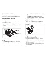
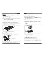
Page 4: ...has been disconnected from its external power source To install the power supply in either the CPSMC18xx xxx or the CPSMC19xx 100 PointSystem chassis 1 Slide the power supply ON OFF switch to OFF as shown in Figure 4 Master Slave Management Manual Figure 3 Configuration Switch Positions OFF ON Power Supply ON OFF Switch Power ON LED Terminal Block Figure 4 Power Supply Power ON LED Terminal Block ...

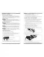
Page 5: ...F disconnect device open 3 First onnect the power source ground lead to chassis ground See Figure 8 4 Connect the positive DC lead to the terminal block 5 Connect the negative DC lead to the terminal block External Power Cables Power Supply Terminal Block Figure 8 Power Supply Terminal Block and External Power Cable Connections techsupport transition com Click the Transition Now link for live Web ...

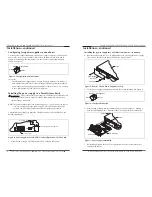
Page 6: ...upply Removal and Installation Management Master Slave Manual Four Position Configuration Switch Instant Failover IFO Board Figure 12 Power Supply configuration Switch techsupport transition com Click the Transition Now link for live Web chat 11 Maintenance continued Configuring the power supply continued 3 Ensure that the module is firmly seated inside the chassis 4 Re install the two 2 6 32 phil...

Page 7: ...If the power supply module fails or is not working properly isolate and correct the problem by determining the answers to the following questions and then taking the indicated action 1 Is the Power ON LED lit YES Note In a dual power supply chassis make sure that one power supply s configuration switch is set to Master and the second set to Slave See Configuring two power supplies in one chassis p...

Page 8: ...eclare that the equipment specified above conforms to the above Directive s and Standard s Aug 5 2005_____ Stephen Anderson Vice President of Engineering Date techsupport transition com Click the Transition Now link for live Web chat 15 Compliance Information CISPR22 EN55022 Class A B CE Mark1 FCC regulations This equipment has been tested and found to comply with the limits for a Class A B digita...

Page 9: ...ht restrictions 2000 2004 2005 Transition Networks All rights reserved No part of this work may be reproduced or used in any form or by any means graphic electronic or mechanical without written permission from Transition Networks Printed in the U S A 33187 C CPSMP 210 48VDC and CPSMP 220 24VDC Power Supplies ...

Reviews: