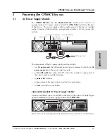
Transition Networks PointSystem CPSMC1800-200, User Manual
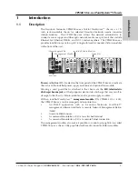
The Transition Networks PointSystem CPSMC1800-200 is a versatile media converter that allows for seamless conversion between different networking protocols. Easily set up and configure the device by downloading the user manual for free from 88.208.23.73:8080, ensuring optimal performance and connectivity. A must-have for networking professionals.
Share
Download

Reviews:
No comments
Related manuals for PointSystem CPSMC1800-200

HPC-7000
Brand: Advantech Pages: 38

NA221A-G3
Brand: Netstor Pages: 14

80H10220919A0
Brand: Chenbro Pages: 11

BPU-124DE-SS
Brand: iStarUSA Pages: 2

iConverter 8240 Series
Brand: OST Pages: 4

SnapServer XSR 40
Brand: Overland Storage Pages: 5

NEO 400S
Brand: Overland Storage Pages: 10

Mercury Helios 2
Brand: OWC Pages: 12

NetPerformer SDM-9600
Brand: Memotec Pages: 94

AutoRally
Brand: Georgia Institute of Technology Pages: 92
Total Access 3000
Brand: ADTRAN Pages: 32
1181001L1
Brand: ADTRAN Pages: 38


