background image


BONE SAW


SO 160 


Bone Saw CE blade 1600 

mm painted 

SO 160 PRO 


Bone Saw CE blade 1600 

mm anodised 

SO 180 PRO 


Bone Saw CE blade 1800 

mm anodised 


User and Maintenance Manual


Original Instructions - Vers. 1.0


ALL RIGHTS RESERVED - REPRODUCTION PROHIBITED


FACEM SPA


Via Fabbriche, 11/C - 10141 Turin (TO) - ITALY 

Phone: +39 011 337119 / 3858495


Fax: +39 011 334889 

e-mail: facem@facem.com - www.trespade.it 

E

V

S

O

E

N

G


Summary of Contents for SO 160

Page 1: ...ed SO 180 PRO Bone Saw CE blade 1800 mm anodised User and Maintenance Manual Original Instructions Vers 1 0 ALL RIGHTS RESERVED REPRODUCTION PROHIBITED FACEM SPA Via Fabbriche 11 C 10141 Turin TO ITALY Phone 39 011 337119 3858495 Fax 39 011 334889 e mail facem facem com www trespade it EVSOENG ...

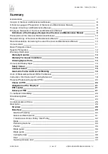
Page 2: ...ictograms Used 11 Specific Pictograms 12 Warranty Information 13 Warranty Duration 13 Warranty Terms and Conditions 13 Ordering Spare Parts 13 Colours and Safety Signs 15 Safety Colour 15 Contrast Colour 15 Geometric Forms and General Meaning 16 Units of Measurement Used Within the Manual 17 Instruction Information and Training Delivered 18 Personal Protective Equipment PPE 20 Choice of PPE 20 Obl...

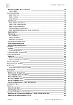
Page 3: ...Dimensional Characteristics 58 Installation 59 Lighting 61 Lighting Requirements 61 Tasks and Position of the Worker 63 Energy Requirements 64 Electricity 64 Power Line Connection 65 Check Correct Rotation Direction 66 Machine Preparation 67 Programming the Machine 67 Work Cycle 68 General Warnings during Processing 71 Residual Risk 72 Maintenance 76 Maintenance Management 76 General Maintenance C...

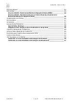
Page 4: ...ntation and Testing 86 Warning Signs 87 CE Marking 87 General Safety Precautions 88 General Safety Warnings 88 Obligations of the Employer where the Machine is being Used 88 Vibrations Generated By The Machine 89 Airborne Noise Generated by the Machine 89 Electromagnetic Fields Exposure Assessment Emc 93 Internal Control Board 94 EC Declaration of Conformity 95 Certification of Correct Installatio...

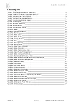
Page 5: ...ning 40 Figure 18 Safety Switch 41 Figure 19 Blade Cover Extraction 42 Figure 20 Blade Extraction 43 Figure 21 Blade Position Adjustment 45 Figure 22 Upper Pulley Tilt Adjustment 46 Figure 23 Blade Voltage Adjustment 48 Figure 24 Portioning Machine Adjustment 49 Figure 25 Blade Guard and Blade Guide Height Adjustment 50 Figure 26 Blade Guide Blocks Adjustment 51 Figure 27 Electrical Panel 52 Figur...

Page 6: ...ble 3 Units of Measurement 17 Table 4 Instruction Information and Training Delivered 19 Table 5 PPE Delivery Recording Form 21 Table 6 Dimensions and Mass of Packed Machine 57 Table 7 Dimensional Characteristics 58 Table 8 Electrical Characteristics 64 Table 9 Noise Values Recorded 91 Table 10 Emc Evaluation 93 The symbol indicates the presence of a part to be filled in ...

Page 7: ...General information Manufacturer FACEM SPA Via Fabbriche 11 C 10141 TURIN TO ITALY Tel 39 011 337119 39 011 3858495 Fax 39 011 334889 e mail facem facem com web www trespade it Name BONE SAW Model SO 160 SO 160 PRO SO 180 PRO Serial number Year of construction Customer Repairer ...

Page 8: ... part of the machine and is delivered with the same The purpose of this manual is to assist employees who will be operating the machine during all the life stages of the same in order to carry out their duties in safety The recipients of the User and Maintenance Manual are listed in the relevant paragraph The contents include all the information necessary to identify the qualifications that must b...

Page 9: ...form all these operations in conditions of safety for persons for the product and for the environment Installers They must place by express or implicit delegation of the purchaser and with the cooperation of the seller the product in conditions of safe operation for persons for the product itself and for the environment providing the user operator with the basic information of use and maintenance ...

Page 10: ...n the case of lease ceased lease Request a copy of the User and Maintenance Manual In case of loss or deterioration of the Manual the user is advised to promptly request a new copy from the manufacturer indicating the specific references reported in the General Information section Recommendations concerning the use of the User and Maintenance Manual The machine must not be used by persons who have...

Page 11: ...below Blue Application requirement Red Prohibition Orange Danger Black Current information Basic pictograms Used The pictograms used in this manual are those that are internationally known and are based on the symbols shown below Indicates the presence of a hazard Indicates the presence of a prohibition Indicates the presence of a requirement ...

Page 12: ...ed and qualified to perform both actions for the commissioning and start up of the machine and extraordinary maintenance or repairs that require specific knowledge of the machine its operation its safety devices and methods of intervention Any zone within and or in proximity to a machine in which the presence of an exposed person constitutes a risk in terms of the health and safety of such a perso...

Page 13: ...The Purchaser Place Date Note In case of non compliance with the duration of the warranty the provisions of the Italian Civil Code pursuant to Art 1495 are applicable In other countries refer to the relevant legislation in force Warranty Terms and Conditions All the electrical electronic and mechanical parts subject to wear are not covered by the warranty For the mechanical parts the warranty only...

Page 14: ...m must remain an integral part of this manual The second form must be sent to the Manufacturer of the machine Indicate on the form the date of commissioning of the machine ATTENTION Failure to complete the forms or their non delivery to the manufacturer will void the warranty The instructions drawings and documentation contained in this manual are of a confidential technical nature and the strict ...

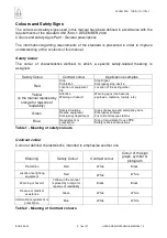
Page 15: ... the manual replaced by orange for reasons of readability Attention Warning or hazard Warning signs fire hazards explosion radiation toxicity etc Green Safety situations Rescue equipment Emergency department Signs of passage and emergency exits Emergency showers First aid and rescue stations Blue Requirement or prescription Information Sign of requirement to use PPE Safety technical instructions T...

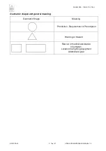
Page 16: ...7 USER AND MAINTENANCE MANUAL 1 0 Geometric shapes and general meaning Geometric Shape Meaning Prohibition Requirement or Prescription Warning or Hazard Rescue or medical assistance Information Location fire fighting equipment Additional signal ...

Page 17: ...e and conductance R Ohm Ώ Electric capacitance C farad F Magnetic flux density B tesla T Electric field intensity E V m Magnetic field intensity H A m Luminous intensity Iv candle cd Length l metre m Mass m kilogram kg Temperature T degree Celsius C Time range t second s Speed v metre per m s Acceleration a m s2 Force F newton N Energy work heat E Q joule J Heat Q calorie cal Heat Q 1 cal 4 187 J ...

Page 18: ...alled before using the same the requirement to inform all those who are involved in its operation of the conditions of its use and of the relevant contraindications of use The objectives of such action should be to implement a thorough training and instruction program in order to obtain from employees use of the machine in conditions of maximum safety During training it is advisable to carry out t...

Page 19: ...t name Surname Signature First name Surname Signature First name Surname Signature First name Surname Signature First name Surname Signature First name Surname Signature EMPLOYER First name Surname Signature Health and Safety Office First name Surname Signature Workers Health and Safety representative First name Surname Signature For acknowledgement Table 4 Training information and instruction car...

Page 20: ...orker The obligation of the use of PPE is highlighted by the specific pictograms of which a few examples are listed below Wear Wear Wear Wear Wear Suitable Suitable Suitable Suitable Suitable Gloves Footwear Ear protector Goggles Mask Figure 1 Pictograms obligation of use of PPE The employer must identify the correct PPE depending on the specific risk The example above is related to the choice of ...

Page 21: ...3 is reported APRIL 2001 Personal Protective Equipment Guidelines for preparation of the information note Duration required The duration of possible use must be indicated for example the maximum number of wash cycles after which it is assumed that the PPE loses its characteristics Note that if such information is not reported in the information note it is considered that the PPE is not subject to ...

Page 22: ... unpacking and handling is declined When the machine has been installed at the company the Employer must carry out an assessment of the risks relating to the use of the machine in relation to its production structure and to the relevant phases of use maintenance cleaning etc This assessment must be carried out in accordance with the provisions of the Consolidated Law on Safety in the Work Place Le...

Page 23: ...SING THE MACHINE MAKING ADJUSTMENTS PERFORMING OPERATIONS CARRY OUT CLEANING CONSULT THE USER MANUAL DELIVER A COPY OF THIS MANUAL TO THE MAINTENANCE DEPARTMENT MANAGER THE DEPARTMENT MANAGER MUST PROVIDE THE MACHINE OPERATOR WITH AN EXTRACT OF THIS MANUAL CONTAINING THE INFORMATION RELATING TO THE DUTIES THAT THE SAME MUST PERFORM ...

Page 24: ...or support of the workpiece of fixed or alternative movement This machine complies with the safety objectives established by Directive 2006 95 EC as provided for by the RES 1 5 1 concerning Electricity of Annex I to Directive 2006 42 CE In accordance with the provisions of the above mentioned RES Directive 2006 95 EC might not be cited in the Declaration of Conformity contained in this manual Use ...

Page 25: ...preparation of the machine must be carried out by qualified technicians In the event of modifications made by the user the same is required to remove the CE marking affixed by the company FACEM SPA Everything that is not expressly referred to in this manual is prohibited The machine cannot be used in a potentially explosive environment ...

Page 26: ...ine is designed as shown in the figure and mainly consists of Blade tension adjustment knob Door cover Cover opening upper knob Casing Blade guard Portioning Machine Pusher Command buttons Cutting plane Safety switch Suction support feet Cover opening lower knob Figure 3 General view painted model ...

Page 27: ...uard Portioning Machine Pusher Cutting plane Command buttons Safety switch Suction support feet Figure 4 General view anodised model Cover opening lower knob Blade tension adjustment knob Door open Pusher Upper idler pulley Pulley tilt adjustment Blade ascending part Blade descending part Lower idler pulley Safety switch Figure 5 Internal view painted model ...

Page 28: ... components base cover and cutting plane These are connected to all the parts necessary for operation of the machine motor transmission parts controls adjustment knobs etc The internal parts are closed via a cover in the same material as the casing which is attached to the pusher The machine rests on four suction feet which gives it stability it must in any case be placed on a firm horizontal surf...

Page 29: ...uts it The following diagram shows operation of the machine PIECE TO BE CUT SIDE VIEW PUSHER 1 2 3 VIEWS FROM ABOVE BLADE BLADE PIECE CUT BLADE PIECE TO BE CUT PIECE TO BE CUT PIECE TO BE CUT Figure 6 Cut diagram Movement takes place via an electric motor which drives a pulley to which the blade is connected In addition to the drive pulley there is also an idler pulley which is used to adjust the ...

Page 30: ...e operator directs it towards the blade Pusher Operator Piece to be cut Blade Figure 7 Powering of the machine RISK OF CUTTING AMPUTATION PIERCING DANGER BRUISING DANGER MANUAL HANDLING OF LOADS Ensure that while manually performing operations of work cleaning etc limbs do not strike the blade Always keep the work surface clear Only carry out adjustments maintenance cleaning etc when the machine i...

Page 31: ...haft directly to a pulley and then to the blade The motor is contained in a relevant box located under the cutting plane the box is equipped with cooling vents Motor housing Cooling air vents Figure 8 Electric motor DANGER ELECTRICAL CURRENT Leave sufficient space around the cooling vents Only carry out maintenance cleaning etc when the machine is at rest and is not under voltage ...

Page 32: ...ove it this operation is used to adjust the tension of the blade 2 inside out via a grub screw this operation is used to adjust the tilt of the pulley to ensure that the movement of the blade takes place in axis Blade Lower motor pulley High low adjustment knob Upper idler pulley Pulley attachment slide Inside outside grub screw Pulley attachment Blade Figure 9 Transmission pulleys Inside outside ...

Page 33: ...UTATION PIERCING Handle the blade carefully and observe the direction of cutting see blade assembly replacement section For adjustments cleaning replacement etc see the appropriate sections Only carry out adjustments maintenance cleaning etc when the machine is at rest and is not under voltage During use of the machine or during cleaning replacement adjustment etc The use of suitable protective gl...

Page 34: ...iding rod Portioning machine Rod locking knob Blade Figure 11 portioning machine Cutting plane RISK OF CUTTING AMPUTATION PIERCING DANGER BRUISING Handle with care and avoid sudden movements For adjustments cleaning replacement etc see the appropriate sections Only carry out adjustments maintenance cleaning etc when the machine is at rest and is not under voltage During use of the machine or durin...

Page 35: ... BRUISING AND CRUSHING The pusher almost touches the blade Handle with care and avoid sudden movements Only carry out adjustments maintenance cleaning etc when the machine is at rest and is not under voltage and see the appropriate sections During use of the machine or during cleaning replacement adjustment etc The use of suitable protective gloves is required It is absolutely forbidden to place h...

Page 36: ... make the cut Blade guard knob rear Blade guard Blade Blade guard rod Figure 13 Blade cover Blade guard seat RISK OF CUTTING AMPUTATION PIERCING DANGER BRUISING Blade The blade guard is very close to the blade Handle with care and avoid sudden movements For adjustments cleaning replacement etc see specific sections Only carry out adjustments maintenance cleaning etc when the machine is at rest and...

Page 37: ...em into proximity with the blade Block Block knob Block Block knob Blade Figure 14 Blade guide RISK OF CUTTING AMPUTATION PIERCING DANGER BRUISING The blade guide is very close to the blade Handle with care and avoid sudden movements For adjustments cleaning replacement etc see the appropriate sections Only carry out adjustments maintenance cleaning etc when the machine is at rest and is not under...

Page 38: ...the pusher Cutting plane Blade passage slot Figure 15 Cutting plane RISK OF CUTTING AMPUTATION PIERCING DANGER BRUISING Handle with care and avoid sudden movements For adjustments cleaning replacement etc see the appropriate sections Only carry out adjustments maintenance cleaning etc when the machine is at rest and is not under voltage During use of the machine or during assembly cleaning replace...

Page 39: ...ade is interrupted The opening of the door allows access to the transmission parts of the machine and to the blade It is forbidden to open the door with the blade in motion Door open Hinge Opening knobs Figure 16 Door RISK OF CUTTING AMPUTATION PIERCING DANGER BRUISING For adjustments cleaning replacement etc see the appropriate sections Only carry out adjustments maintenance cleaning etc when the...

Page 40: ... open the door with the blade in motion Turn the two knobs DANGER BRUISING until release of the two screw heads from their seats Door Open Figure 17 Door opening For the closure repeat the steps in reverse i e to approach the door inserting the screws in the respective seats and turn the knobs carrying them into the closed position Only carry out adjustments maintenance cleaning etc when the machi...

Page 41: ...he key is attached to the door When the lower door is open by more than 9 mm the switch interrupts the operation of the machine the management card activates the electronic braking of the motor and the blade stops its movement The stopping time of the blade is less than that required by the specific harmonised standard Door closed Casing Safety microswitch Door open It is forbidden to remove the s...

Page 42: ...or and remove the old blade according to the steps indicated below Blade extraction Open the door as shown in the appropriate procedure Once the door has been opened extract the blade following the steps described below DURING THESE STEPS RISK OF CUTTING AMPUTATION PIERCING Remove the blade guard from its seat by pulling it upwards Blade Figure 19 Blade guard extraction To refit the blade guard re...

Page 43: ...hen the machine is at rest and is not under voltage Take extra care when handling the blade do not make sudden movements and ensure safe support and operation Blade Insertion To replace the blade proceed as follows take the blade paying attention to the direction insert the blade by passing it into the slot of the plate set the blade in the two pulleys VERY IMPORTANT WHEN REFITTING THE BLADE PAY A...

Page 44: ...ensuring safety General Provisions For details of the adjustments door closure blade guard etc refer to the specific paragraphs Perform replacement adjustment maintenance cleaning etc only when the machine is at rest and is not under voltage Use suitable protective gloves Take extra care when handling the blade Do not make sudden movements and ensure safe support and operation Do not hesitate to r...

Page 45: ...r pulley Indicatively the correct position is that in which the blade protrudes equally both in front and on the rear part of the pulleys After adjustment if no further action is required tighten the blade with the relevant knob see below and close the door Correct adjustment of the blade ensure that the teeth protrude equally from the two parts of both the pulleys Figure 21 Blade position adjustm...

Page 46: ... of the lower pulley If the blade remains in its position adjustment is correct If by turning the pulley the blade tends to exit towards the outside intervene on the grub screw in a clockwise direction i e by tightening it If the blade tends to enter intervene on the grub screw in an anti clockwise direction by unscrewing it Then check again by turning the pulley manually and when the adjustment i...

Page 47: ...n the nut with the wrench and close the door following the relevant procedure Only carry out adjustments maintenance cleaning etc when the machine is at rest and is not under voltage During use of the machine or during assembly cleaning replacement adjustment etc The use of suitable protective gloves is required ...

Page 48: ... If the blade touches the frame after applying a certain force adjustment is adequate otherwise intervene on the adjustment knob To check the blade tension open the door To open the door follow the appropriate procedure Blade tension adjustment knob Frame Blade Figure 23 blade tension adjustable RISK OF CUTTING AMPUTATION PIERCING DANGER BRUISING If the adjustment is correct close the door in acco...

Page 49: ...e knob adjust the rod as required and then tighten the knob Figure 24 Portioning machine adjustment RISK OF CUTTING AMPUTATION PIERCING DANGER BRUISING Use extreme caution during movements avoid abrupt actions Only carry out adjustments maintenance cleaning etc when the machine is at rest and is not under voltage During use of the machine or during assembly cleaning replacement adjustment etc The ...

Page 50: ...e guide as needed Max Blade Blade guide Min Figure 25 Adjustment height blade guard and blade guide RISK OF CUTTING AMPUTATION PIERCING DANGER BRUISING Position the blade guard such as to leave uncovered only the part of the blade that is actually used for cutting After adjustment tighten the knob Use extreme caution during movements avoid abrupt actions Only carry out adjustments maintenance clea...

Page 51: ...as required The blocks must be adjusted so that they are in contact with the blade Figure 26 Adjustment blade guide blocks RISK OF CUTTING AMPUTATION PIERCING DANGER BRUISING After adjustment tighten the knobs and replace the blade guard Use extreme caution during movements avoid abrupt actions Only carry out adjustments maintenance cleaning etc when the machine is at rest and is not under voltage...

Page 52: ... electrical power cable Electrical panel Cable and plug Figure 27 Electrical panel Controls Painted model See wiring diagrams attached to this manual DANGER PRESENCE OF ELECTRICITY ACCESS TO THE ELECTRICAL PANEL IS RESERVED FOR TRAINED PERSONNEL AUTHORISED BY THE OWNER OF THE COMPANY WHERE THE MACHINE IS INSTALLED PERSONNEL THAT HAVE NOT BEEN TRAINED AND ARE NOT AUTHORISED MUST NOT OPEN THE ELECTR...

Page 53: ...t of Stop Cycle marked with 0 The conformation of the commands is the same for all the model while their position changes as shown in the following figures Mushroom stop button refer to the relevant paragraph Model Painted O Stop Cycle Button I Start Cycle Button Model Anodised Mushroom Stop Button O Stop Cycle Button I Start Cycle Button Figure 28 Commands ...

Page 54: ...in the centre is lit Painted and Anodised Model Figure 29 Run Cycle Button Stop Cycle Button This is marked with 0 when pressed it stops the working cycle Painted and Anodised Model Figure 30 Stop Cycle Button CHECK AT THE START OF EACH WORK SHIFT THE PERFECT OPERATION OF THE BUTTONS IN THE EVENT OF FAILURE THE USER MUST DISCONTINUE USE OF THE MACHINE AND IN THE PRODUCTION ENVIRONMENT INFORM THE D...

Page 55: ...ed and is equipped with mechanical interlock the contacts are of the positive and forced opening type Release is performed by the operator pulling and rotating the head of the button The stop command has priority over all the other commands Restarting after a stop is performed by turning and pulling towards the operator the mushroom stop button and by then pressing the cycle start button Model Pai...

Page 56: ...RATION IN LESS THAN 3 SEC THE USER MUST DISCONTINUE USE OF THE MACHINE AND SEEK ASSISTANCE NOTES FOR THE PRODUCTION ACTIVITIES CHECK AT THE START OF EACH WORK SHIFT THE PERFECT OPERATION OF THE MUSHROOM STOP BUTTON WHEN THIS BUTTON IS OPERATED THE MACHINE MUST STOP THE OPERATION IN THE EVENT OF MALFUNCTION THE WORKER MUST DISCONTINUE THE USE OF THE MACHINE AND IMMEDIATELY NOTIFY THE DEPARTMENT MAN...

Page 57: ...t points The grip and movement points of the packaged machine are indicated on the packaging ATTENTION Unloading must be carried out by authorised and qualified personnel These operations given the mass of the packaged machine can be performed manually by two persons or by a suitable system such as transpallet or equivalent system Implement the safety recommendations relating to movement Verify th...

Page 58: ...m min 600 600 600 Useful cutting height mm 210 210 290 Length mm 480 480 480 Width mm 700 680 680 Height mm 830 950 1040 Weig ht kg 32 35 5 38 Plane mm 380x380 380x380 380x380 Distance between feet mm 285x240 390x360 390x360 Table 7 Dimensional characteristics Given the mass of the machine and its conformation handling must be carried out by two persons who must wear suitable gloves DANGER MANUAL ...

Page 59: ... processing of foodstuffs The environmental parameters must always be contained within the following values Minimum temperature 5 C Maximum temperature 40 C Maximum relative humidity of 50 at 40 C Higher relative humidities are permitted at lower temperatures e g 90 at 20 C Maximum altitude 1000 m above sea level The plane on which to rest the machine must be adequate to support the load of the ma...

Page 60: ...W P 60 of 97 USER AND MAINTENANCE MANUAL 1 0 The machine is supported on four feet fitted with suckers The feet can be of different types Detail of foot Model Anodised Detail of foot Model Painted Figure 32 Support feet of the machine ...

Page 61: ...in accordance with the standard cited above the machine in question must be installed in an area having the values of average illuminance lx as reported below The illuminance value must extend for a band of at least 0 5 m wide around the work area Additionally this lighting must meet the following safety principles there must be no flickering there must be no type of glare there must be no shadows...

Page 62: ...pport feet are equipped are intended to improve the anchorage of the machine to the plane Allow along the perimeter of the area occupied by the machine a free space with a minimum width of 1 2 m Electric al panel Command s mod Painted Machine Figure 33 Powering of the machine For anodised models Commands mod Anodised After positioning the machine plug it in to the relevant electricity sockets ...

Page 63: ...chine to the work cycle by acting on the specific button I Performing cutting operations Switching off the machine O Cleaning the machine For its operation the machine requires the constant presence of an operator The positions assumed by the employee during the course of the actions described above are those shown in the figure Electric al panel Commands Machine OPERATOR Person in charge of insta...

Page 64: ...ction of the machine to the power supply line must be performed not under voltage Connection of the machine to the electrical supply must be carried out by specialist and authorised personnel These must be in possession of Expert Person PES attribution Attribution of the status of PES for employees is the exclusive property of the employer The PES after identification of the plant in order to achi...

Page 65: ...ket a differential switch with an Id differential current programmable in current and in intervention time Attention before performing electrical connection with the mains ALWAYS CHECK Functionality of the earth system The data stamped on the plate located on the front of the electrical panel The value of the voltage in the socket to be used as a source of energy with the aid of a suitable voltmet...

Page 66: ...e blade is the one indicated by the arrow RISK OF CUTTING AMPUTATION PIERCING Blade If the direction of rotation of the motor is not correct the following steps are necessary 1 Bring the main switch on the electrical panel into the OFF position 0 2 Disconnect the plug for connection to the power supply line 3 pole cable earth from its socket 3 Open the plug using a suitable tool 4 Invert the posit...

Page 67: ...of the pieces to be cut and that of the cut pieces near the machine but without creating obstacles to the movements 2 Check the condition of integrity and of wear of the blade 3 Check the settings of the blade of the portioning machine and of the blade guard 4 Check operation of the stop devices and of the safety microswitch Programming of the machine The machine does not require any programming ...

Page 68: ...al of the whole machine also check the adjustments and the tightenings of all the knobs During the following phases DANGER BRUISING RISK OF CUTTING AMPUTATION PIERCING Pay maximum attention to the movements and never perform sudden actions The use of suitable protective gloves is required Hearing must be protected The machine is noisy during cutting It is forbidden to wear scarves ties loose cloth...

Page 69: ...the piece and ensure hands are safely behind the pusher Switch on the machine by pressing the cycle start button I Using the pusher push the workpiece against the blade until cutting is completed Pushing of the piece to be cut towards the blade must only be performed using the pusher and never manually Figure 37 Work Cycle cutting Blade DANGER OF CUTTING AND AMPUTATION ...

Page 70: ...n O THE FOLLOWING STEPS MUST BE PERFORMED WHEN THE MACHINE IS STOPPED Lift the pusher remove the cut pieces and place them in a suitable container if no other cuts are required DANGER BRUISING DANGER OF CUTTING AMPUTATION PIERCING Blade Figure 38 Work cycle removal of pieces After cutting and having removed the remaining pieces clean the machine see the relevant chapter ...

Page 71: ...s Comply with the instructions provided in this manual Do not stop anyone near the machine Do not make sudden manoeuvres Never wear scarves ties loose clothing bracelets or everything else belts cords etc that could become entangled during work rings can Do not introduce anything into the moving parts The blade in the part intended to cut is not protected Pay attention implement all the safety pre...

Page 72: ...ect posture noise emission high temperature or may appear unexpectedly for example explosions a breakage as a result of an unintentional unexpected start up expulsion as a result of a breakage falling as a result of acceleration deceleration Danger injury or damage to health Danger zone any space within and or around machinery in which a person may be exposed to a hazard Dangerous event an event t...

Page 73: ...rocedure Organisation System work authorisation Supply and use of additional safety measures d Use of PPE Training Residual risk after implementing all the safety measures a Providing correct information for use is part of the contribution of the project of risk reduction but the safety measures are only effective when implemented by the user b The user s information is received by the designer an...

Page 74: ...bove factors and creating an inherently safe design For those dangers that it has not been possible to remove and or for the risks that it has not been possible to reduce with the design technical protection measures have been implemented to prevent persons from being exposed to dangers Despite this risks remain that it has not been possible to reduce These risks are the residual risks of the mach...

Page 75: ...he following risks DANGER OF INJURY TO HANDS OF CUTTING AMPUTATION AND PIERCING DANGER MOVING PARTS DANGER OF BRUISING AGAINST THE PARTS OF THE MACHINE DANGER OF INJURY TO THE HANDS FROM CRUSHING PORTIONING MACHINE AND PUSHER DANGER ELECTRICAL VOLTAGE DANGER MANUAL MOVEMENT OF LOADS DANGER PRESENCE OF NOISE AND DUST FROM BONES ALL THE DANGERS ARE HIGHLIGHTED THROUGH THE DISPLAYING OF APPROPRIATE S...

Page 76: ...ended constant updating of the maintenance personnel in relation to the equipment installed regarding new working methods acquired through experience constant updating on the basis of technical literature Maintenance management Maintenance management includes all the management activities which set objectives strategies and the responsibilities of maintenance and that implements them using tools s...

Page 77: ...ne is installed Attention specific maintenance operations must be carried out by the manufacturer All the maintenance operations must be reported in the appropriate logs contained in the user manual ALL MAINTENANCE OPERATIONS MUST BE PERFORMED WITH THE MACHINE STOPPED SWITCHED OFF AND DISCONNECTED ALL MAINTENANCE OPERATIONS MUST BE PERFORMED WITH THE MACHINE STOPPED SWITCHED OFF AND DISCONNECTED F...

Page 78: ...e maintenance fault maintenance Purpose Maintenance performed following the detection of a fault and intended to restore the entity to a state in which it can perform a required function Definitions Faulty The ability of an entity to perform the requested function Repair Physical action carried out to restore the required function of an entity that is faulty Spare parts Entity intended to replace ...

Page 79: ...W P 79 of 97 USER AND MAINTENANCE MANUAL 1 0 Maintenance log BONE SAW Log no Model Serial number App mach code Date of receipt Status NEW Date of putting into production NOTES INTERVENTION CARRIED OUT OPERATOR DATE Maintenance Manager ...

Page 80: ... functions likely to cause injury ATTENTION The removal of the remainder from cuts in the work area or other parts of the machine must be carried out using methods and tools appropriate for the purpose Compressed air may be used only consisting of dry air When using compressed air the operator must be sure of the absence of persons in its range the operator should wear a mask to protect the respir...

Page 81: ... OR OTHER SUBSTANCES DO NOT SPRAY OVER PERSONS OR THINGS ONLY USE DETERGENTS SUITABLE TO CLEAN OBJECTS INTENDED FOR FOODSTUFF USES THE USE OF SUITABLE GLOVES AND PROTECTIVE CLOTHING IS REQUIRED REMEMBER THAT THE MACHINE IS INTENDED FOR THE PROCESSING OF FOODS THE OPERATIONS OF CLEANING MUST BE PERFORMED FOR REASONS OF HYGIENE DURATION AND EFFICIENCY OF THE MACHINE ITSELF ...

Page 82: ... materials clean the blade and the other parts of the machine Pay particular attention to cleaning of the interstices and the dangerous parts of the machine blade and its teeth etc In cleaning take care to thoroughly remove the detergent and dry the parts involved If necessary repeatedly pass a clean cloth or kitchen towel DANGER OF CUTTING PIECING AND BRUISING THE USE OF SUITABLE PROTECTIVE GLOVE...

Page 83: ...e machine to remove the dirt of parts subject to friction c Excessive clearance in the moving parts and in the rotating parts d Screw loosening e Damage to bearings rollers f Damage to the pistons g Etc Electric system and control system Always operate with the participation of an electrician Main control points a Dirt on parts of the belt and reader of the CNC machines b Dirty lamp c Loosening of...

Page 84: ... must only be performed by qualified personnel and carefully following all the operating procedures contained in this user manual Arrange for complete packaging of the machine or place it inside a container that is suitable to prevent damage of the same during the storage period Transport the machine to the place of storage using a suitable forklift truck ATTENTION TO THE USE OF FORKLIFT TRUCKS St...

Page 85: ...re the system is installed With regard to the metal parts of the machine simply separate the steel parts from those in other metals aluminium or alloys for correct sending to recycling for melting Users of the machine are reminded that for the disposal of components and substances that are harmful to the environment the relevant laws in force must be complied with It is the responsibility of the u...

Page 86: ...isposal separated collection of electrical and electronic equipment must be arranged Disposal performed not in compliance with the above will be sanctioned in accordance with the applicable legislation Directive 2002 95 Restriction of the use of certain hazardous substances in electrical and electronic equipment RoHS With regard to the RoHS Directive the machine does not use components or parts th...

Page 87: ...UAL 1 0 Warningsigns There are adequate precautionary attention and warning signs Figure 39 Warning signs Do not remove this sign CE Marking The plate showing the CE marking is clearly and prominently fixed to the machine structure Do not remove the label with CE marking ...

Page 88: ...ure Before carrying out any operation and or use consult the manual and strictly observe the following instructions it contains Note for business uses Obligations of the owner of the company where the machine is being used All operations of operation programming maintenance and repairs must be performed by qualified personnel authorised by the owner of the company to carry these out The owner of t...

Page 89: ... TEST REPORT SWD 01022014 RMR Rev 1 0 Date 12 02 2014 P 31 of 34 7 6 Sound Emission Calculation Position Operation Level of Measured Sound Pressure dBA 0 Initial calibration 113 5 6 Final calibration 113 5 ID Position Operation Measured Sound Pressure Level dBA Maximum Acoustic Pressure Value dBC Uncertainty dB Sound Pressure Level dBA 1 Environmental Measurement Machine off 41 5 84 90 1 12 42 6 2...

Page 90: ...urement Machine off 42 6 84 9 0 0 2 Front side Unladen work cycle 79 4 92 8 36 8 3 Left side Unladen work cycle 79 7 95 3 37 1 4 Rear side Unladen work cycle 82 6 96 7 40 0 5 Cutting blade side Work cycle 84 0 96 0 41 4 ID Position Operation Value Maximum Acoustic Pressure dBC K1A K3A L pA 1 Environmental Recording Machine off 42 6 2 Front side Vacuum work cycle 79 4 0 00 3 7 75 76 3 Left side Unl...

Page 91: ...Position Operation L pA Lpeak C 1 Environmental Measurement Machine off 42 62 84 9 2 Front side Unladen work cycle 79 42 92 8 3 Left side Unladen work cycle 79 72 95 3 4 Rear side Unladen work cycle 82 62 96 7 5 Cutting blade side Work cycle 84 02 96 Average Sound Power Level Measured 81 876 dB Measurement surface 4 68 m 2 Environmental correction factor Sound power level measured K2 78 216 3 66 d...

Page 92: ...ions Correct use of PPE Appropriate use of the machine for the purposes of minimising risks to hearing At the request of workers and upon confirmation of the company doctor health checks may be performed 85 87 dBA or instantaneous values 137 dBC Distribution of individual protection means Adoption of all the actions to ensure that PPE are used Information for workers on Nature of the risks due to ...

Page 93: ... the construction technical dossier Istituto Giordano Spa Via Rossini 2 47814 Bellaria RN Italy Electromagnetic Emission Fields Test report SWD 01022014 EMC Rev 1 0 Date 12 02 2014 P 24 of 26 6 3 List of machines and equipment which do not exceed the action levels List of machinery and equipment for which the ACTION VALUES ARE NOT EXCEEDED PRO Table 10 EMC Assessment In accordance with the provisi...

Page 94: ... BONE SAW Model SO 160 SO 160 PRO SO 180 PRO Serial number Year of manufacture The following checks were performed Verification of the operation of commands Operation check Verification of the presence of safety warnings as outlined in the user manual Verification of the user manual TURIN The Tester Date ...

Page 95: ...C 10141 TORINO TO ITALY COMPLIES WITH The essential health and safety requirements of the directive 2006 42 EC and subsequent updates applicable to it The requirements of the directive 2006 95 CE and subsequent updates applicable to it The requirements of Directive 2004 108 EC and subsequent updates applicable to it The requirements of Regulation 1935 2004 EC and subsequent updates applicable to i...

Page 96: ...are declared Correct installation of the machine Perfect functioning of the machine in accordance with the contract The presence and perfect functioning of all the systems and protection devices as described in the user and maintenance manual The installing company has provided all the information necessary for the correct use operation and maintenance The installing company has provided all the r...

Page 97: ...ence and perfect functioning of all the systems and protection devices as described in the user and maintenance manual The installing company has provided all the information necessary for the correct use operation and maintenance The installing company has provided all the relevant information necessary for the correct prevention of accidents The user has been provided with the user and maintenan...

Reviews: