background image


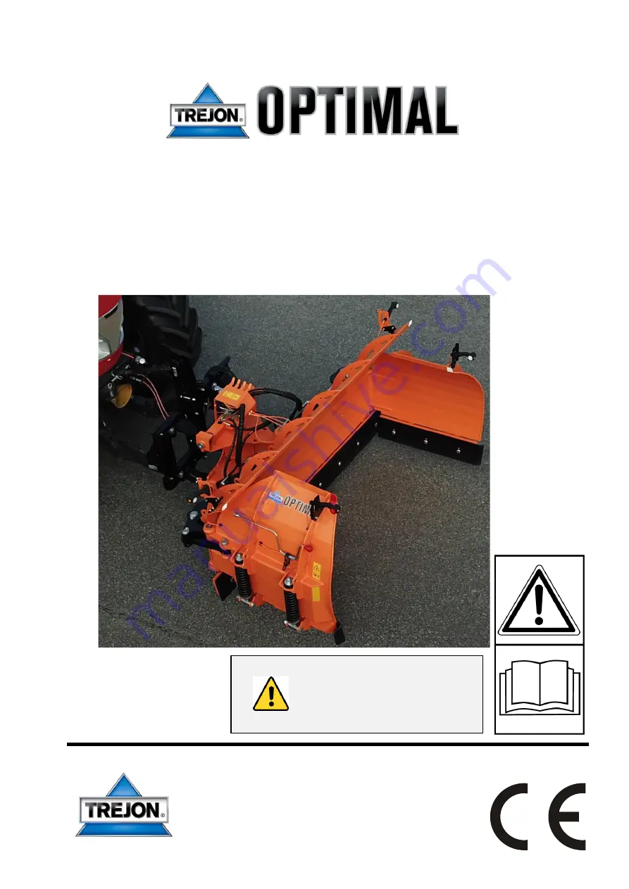
Instruction Manual and 

Maintenance Directions 


UPX plough 


From November 2020 


Important! 

Read the Instruction Manual 

thoroughly before use


TREJON FÖRSÄLJNINGS AB 

Företagsvägen 9 
SE-911 35 VÄNNÄSBY 
SWEDEN 
Tel: + 46 (0)935 39 900 

Web: trejon.se 


Summary of Contents for OPTIMAL UPX Series

Page 1: ...l and Maintenance Directions UPX plough From November 2020 Important Read the Instruction Manual thoroughly before use TREJON F RS LJNINGS AB F retagsv gen 9 SE 911 35 V NN SBY SWEDEN Tel 46 0 935 39...

Page 2: ...Instruction manual TREJON OPTIMAL UPX plough 2010 2...

Page 3: ...bols 22 3 Using the machine 23 3 1 Assembly 23 3 2 Coupling the plough to the machine 24 3 3 Hydraulics 24 3 4 Hydraulic connection diagram 25 3 4 1 4 Hose option Chapter 5 26 3 5 Plough steering inst...

Page 4: ...YOU ARE IN DANGER Warning Labels Be aware of the warning words WARNING and NOTE in safety texts These words have been chosen based on the following guidelines WARNING Warns of dangerous situations wh...

Page 5: ...e life and efficient use of the UPX plough We have produced this manual to give you a good overview of how the plough works as well as the safety and maintenance directions that must be followed when...

Page 6: ...mentally responsible manner Check that the delivery is complete in accordance with the machine order packing note Make sure the machine has been lubricated as described under Service and Maintenance C...

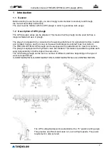
Page 7: ...l tractors loaders and compact tractors and from now on these will collectively be referred to as tool carriers The TREJON OPTIMAL UPX plough can be equipped with an attachment for most tool carriers...

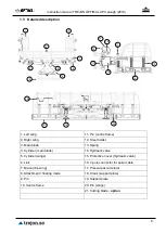
Page 8: ...4 Cylinder main blade 14 Hydraulic valve 5 Cylinder wings 15 Protective cover Hydraulic valve 6 Link 16 7 pole connector for spiral cable 7 Brace link wing 17 Pressure accumulator 8 Attachment floati...

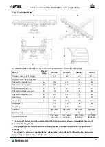
Page 9: ...288 Height cm H 72 96 110 110 Length cm L 1620 1980 2060 2360 Wing angle 170 170 180 180 Weight2 kg 520 850 1000 1100 Operation Hydr Elec Hydr Elec Hydr Elec Hydr Elec El voltage3 V 12 12 24 24 Hydra...

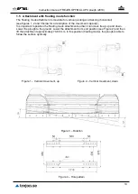
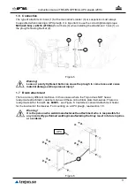
Page 10: ...movement capacity It is important to position the floating mode attachment so that it can move freely up and down Lower the plough to the ground Lower the attachment to its end position see Figure 2 a...

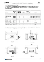
Page 11: ...lough to come loose and cause material damage and or personal injury 1 7 Blank attachment There are many different machines In those cases where the Trejon does NOT have a ready made attachment custom...

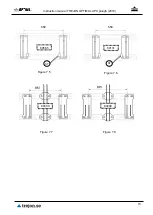
Page 12: ...1 Outside 3 point Cat 2 3N 440109 825 7 2 Wider W side facing inwards Trima 450075 650 7 3 Wider W side facing inwards Euro 450084 995 7 4 Outside Zettelmeyer 502 60565 860 7 5 Inside Zettelmeyer 402...

Page 13: ...Instruction manual TREJON OPTIMAL UPX plough 2010 13 84009 Figure 7 5 Figure 7 6 60131 650 ST 60565 ST 860 Figure 7 7 Figure 7 8 84009...

Page 14: ...be an advantage to raise the UPX plough X 0 see Figure 11 This is done to prevent unnecessary wear on the cutting blades and to avoid cutting up gravel After ploughing a few times or once the roadway...

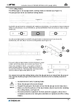
Page 15: ...included in the kit see options Chapter 5 When installing these the same tightening torque must be used for all screws The fixing plate must be pressed into the rubber scraper blade MAX 2 4 mm It is e...

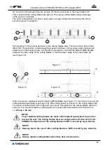
Page 16: ...ades 1 and the lower edge of the steel holder 2 see Figure 16 When the wear is significant and the distance W 10 mm see Figure 17 it is time to move all the cutting blades downwards see Figure 18 When...

Page 17: ...n general cutting angles only need to be adjusted after the springs have been replaced see section 1 12 Dimension Z see Figure 19 can be used as a control measure By tightening the nut M in the upper...

Page 18: ...n the lower part of the spring see Figure 20 2 Tighten nut M1 upwards two turns at a time and test operate Repeat until the tension is just right see Figure 21 3 Tighten nut M2 against nut M1 to lock...

Page 19: ...nts and operating safety features are dependent on the responsible use of the equipment and its integrated safety features Only trained personnel should use this equipment The machine is intended for...

Page 20: ...eep doors and windows close while working All moving parts including engine must be stationary and the handbrake applied before the operator leaves the cab When travelling on ice covered water the roo...

Page 21: ...orbidden Hoses can become hot while in operation with the risk of burn injuries Do not loosen hoses while the oil is hot wait for it to cool down Welding Protect bearings hydraulics and electronic com...

Page 22: ...ier when coupling Always brake the tool carrier turn off the engine and remove the ignition key when leaving the cab during coupling or decoupling operations Indicated lifting point Machine name plate...

Page 23: ...having installed the attachment system read Chapter 1 6 2 With lifting gear such as a chain The lifting gear is attached to the plough wings openings 1 and to the lifting eye 2 by the plough s main bl...

Page 24: ...raulic hoses starting from ports marked P1 and P2 on the valve s hydraulic block These must be connected to double acting hydraulic outlets on the tool carrier At ports P1 and P2 there are two throttl...

Page 25: ...h s hydraulic valve ports C3 C2 are connected with the left wing s cylinder as standard while ports C1 C4 are connected with the right wing cylinder The hydraulic valve s ports C5 C8 are connected wit...

Page 26: ...e tool carrier s double acting hydraulic outlet With this connection the right wing will be operated with the double acting hydraulic function Diagonal main blade and left wing are controlled by the r...

Page 27: ...hydraulic valve 2 x Deutsch connectors marked X6 and X7 are plugged additional information in section 5 accessories Spiral cable 3 5 m 7 pole male male art no TKBL0895 is used to connect electricity...

Page 28: ...ollows with the double acting hydraulic outlet on the tool carrier see the table below Symbol Toggle switch position UPX function Hirschmann connectors LED L down R down Diagonal position Operation of...

Page 29: ...Instruction manual TREJON OPTIMAL UPX plough 2010 29 3 7 Wiring diagram Figure 26 Wiring diagram Control box art no 330006 Figure 27 Wiring diagram Wiring art no 330007 X4 X5 X3 X6 X7...

Page 30: ...r speed than the conditions allow Doubling your speed quadruples your kinetic energy in the event of a collision The weight of the tool carrier is also a decisive factor see Technical specifications C...

Page 31: ...position is recommended when there are large amounts of snow for example when opening up a new road This position provides a good flow through the plough The right wing can be used as a snow stop whe...

Page 32: ...relevant country s traffic regulations and laws 3 10 Disconnection of the plough 1 Lower the plough onto a flat surface so that it rests on the support plates 2 Turn off the tool carrier apply the par...

Page 33: ...ample 4 1 General Carefully maintain the machine in order to obtain a cost efficient operation long service life and retained machine value Use only effective hand tools Keep the machine clean under t...

Page 34: ...on continuous operation requires more frequent lubrication Always lubricate after cleaning with water Service point Interval Action Lubricant Remark Attachment Screw unions Initially 4h then every 8h...

Page 35: ...ubricated and serviced Replace worn or damaged parts When the machine is dry you are recommended to apply a thin coat of oil in those places where the paint has been worn away The piston rods on the h...

Page 36: ...bearing until it comes out at the side of the layer wiping off the excess Rotate the joints if possible 180 and repeat This ensures good distribution of the lubricant Some known brands of grease that...

Page 37: ...bber complete kit UPX500 433075 Support wheel pivoting UPX440 UPX500 use Deutsch connectors marked X6 or X7 for connection to use 2020060 together with 440140 branch cable 2020096 is required Radio co...

Page 38: ...ginal spare parts and accessories are designed especially for these machines The fitting and or use of non original spare parts and accessories can negatively change the technical features of your mac...

Page 39: ...Instruction manual TREJON OPTIMAL UPX plough 2010 39 7 Notes...

Page 40: ...the current basic safety and health protection regulations in accordance with the Machinery Directive 2006 42 EC if applicable and also meets the requirements of other applicable EC standards title a...

Page 41: ...Instruction manual TREJON OPTIMAL UPX plough 2010 41...

Page 42: ...Instruction manual TREJON OPTIMAL UPX plough 2010 42...

Page 43: ...hines already delivered Illustrations in this Instruction Manual do not necessarily show the machine that has been delivered Technical information dimensions and weights are not binding All misprints...

Page 44: ...TREJON F RS LJNINGS AB F retagsv gen 9 SE 911 35 V NN SBY SWEDEN Tel 46 0 935 39 900 Web trejon se...

Reviews: