
1
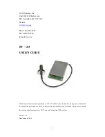
Tri-M Systems,
Inc.
Unit 100, 1407 Kebet way
Port Coquitlam, BC V3C 6L3
Canada
ww
w.tri-m.com
Phone:
604.945.9565
Fax:
604.945.9566
info
@
tri-m.
com
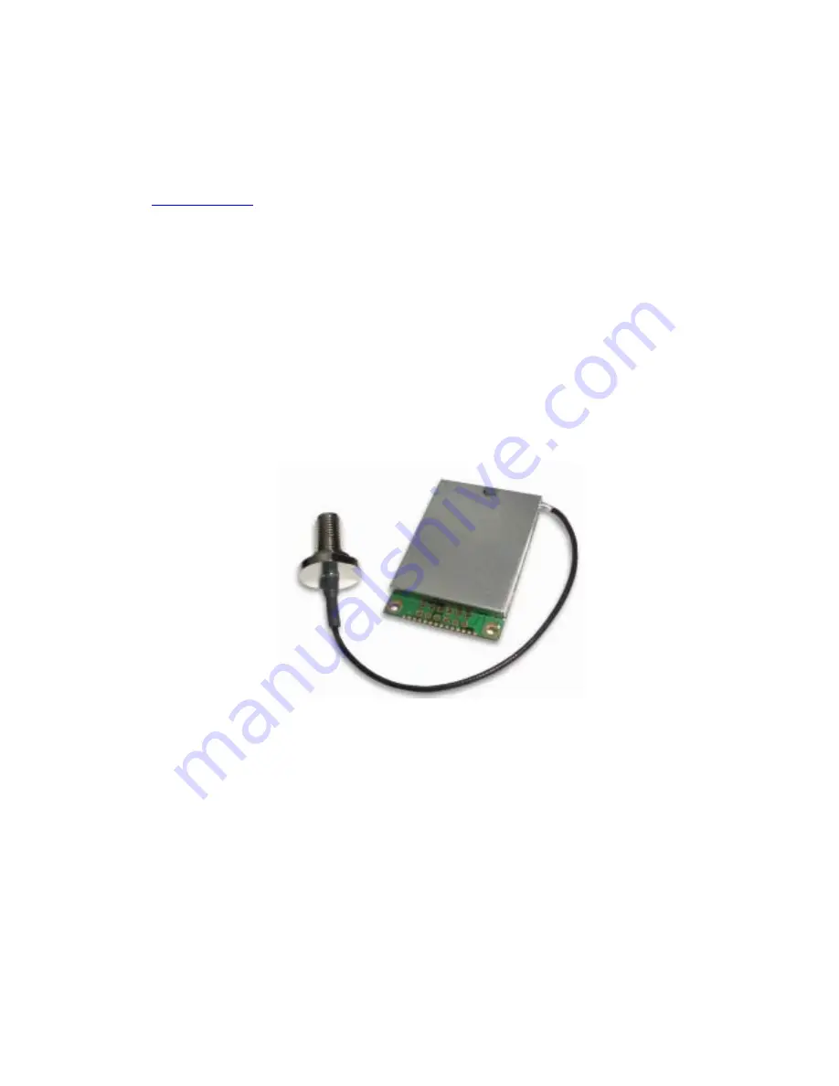
FV – 25
USER’S GUIDE
This document features the specification of FV-25 and describes the details on using the evaluation kit
to evaluate the performance of FV-25 and select the desired functions. It intends to help users to obtain
the maximum performance from FV-25 in users’ integrating GPS systems.
Version: 1.0
Date: January 2005