background image

Trinity Lx  

Model Numbers: Lx200-800 
Version Date: 2013-07-16


APPENDIX C - WATER HEATER APPLICATIONS:  
PLUMBING AND WIRING INSTRUCTIONS


Optional Configuration: Refer to "Appendix B - Boiler Applications" 
Companion Storage Products: TRIN & STOR Storage Tanks


TABLE OF CONTENTS


1.0


INTRODUCTION ................................................................................................................ 2


General Installation Requirements ....................................................................................... 2


Mandatory Wall Mounting Protection .................................................................................. 3


General Water Treatment ..................................................................................................... 3


Potable Water Systems ......................................................................................................... 3


Definitions of Potable Water Systems .................................................................................. 3


Safe Temperatures for Potable Water ................................................................................... 4


2.0


WATER HEATER SYSTEM PIPING ................................................................................. 6


Near Water Heater Plumbing................................................................................................ 6


Water Heater System Plumbing ............................................................................................ 8


Stand Alone Water Heater Applications ............................................................................. 10


Multiple Water Heater Applications ................................................................................... 12


3.0


FIELD WIRING ................................................................................................................. 15


Line Voltage Connections .................................................................................................. 15


Low Voltage Connections .................................................................................................. 18


HAZARD SYMBOLS AND DEFINITIONS 


Danger Sign: Indicates a hazardous situation which, if not avoided, will 
result in serious injury or death. 


Warning  Sign:  Indicates  a  hazardous  situation  which,  if  not  avoided, 
could result in serious injury or death. 


Caution Sign plus Safety Alert Symbol: Indicates a hazardous situation 
which, if not avoided, could result in minor or moderate injury. 


Caution  Sign  without  Safety  Alert  Symbol:  Indicates  a  hazardous 
situation which, if not avoided, could result in property damage. 


Notice  Sign:  Indicates  a  hazardous  situation  which,  if  not  avoided, 
could result in property damage. 


This Water Heater must be installed by a licensed and trained Heating 
Technician  or  the 

Warranty  is  Void.

  Failure  to  properly  install  this 

unit may result in property damage, serious injury to occupants, or possibly death.


NTI # 86572 

NEW FEATURES 

20% Larger Screen 

Tank Sensor Option 

Optional BACnet Gateway 

TRIN & STOR 

Lx 200-800 

Summary of Contents for Lx200-800

Page 1: ... 18 HAZARD SYMBOLS AND DEFINITIONS Danger Sign Indicates a hazardous situation which if not avoided will result in serious injury or death Warning Sign Indicates a hazardous situation which if not avoided could result in serious injury or death Caution Sign plus Safety Alert Symbol Indicates a hazardous situation which if not avoided could result in minor or moderate injury Caution Sign without Sa...

Page 2: ...t will safely operate with Propane Gas Lx150 400 2 Do not convert the Lx600 800 to Propane LP Operate with Natural Gas only General Installation Requirements The installation of your NTI Trinity gas water heater must conform to the requirements of this manual your local authority and the National Fuel Gas Code ANSI Z223 1 and or CAN CGA B149 Installation Codes Where required by the Authority the i...

Page 3: ...ing diagram s for a typical installation Definitions of Potable Water Systems Each potable water system described below is meant to be used with a storage tank refer to Table 1 1 Water Potable Heating Only refers to an open potable water system dedicated to providing domestic hot water and is not intended for space heating Combination Space Heating refers to an open potable water system where the ...

Page 4: ...llness or death High Risk Application Combination space heating systems can present a significantly higher risk of developing Legionella than dedicated domestic hot water systems especially during non heating seasons or low temperature water applications Using higher temperature tank water routinely maintaining your water system and having your water tested annually are considered good practice wh...

Page 5: ...46o C 115o F shall be equipped with a thermostatic mixing valve on the hot water outlet to reduce potential scald hazards Clean aerators and nozzles on water fixtures on a regular basis to reduce scale build up Clean storage tanks and remove sediment Flush storage tanks and piping systems regularly for 10 30 minutes at high water temperatures depending on guidelines used to rid the system of sedim...

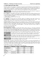
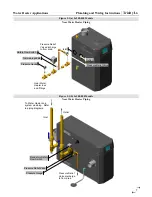
Page 6: ...ater Heater Plumbing Pressure Relief Valve All Trinity Lx models dual certified as either a boiler or a water heater Lx200 800 have an additional factory supplied pressure relief valve For water heater installations use the higher pressure relief value along with the corresponding higher pressure gauge See Table 2 1 for pressure relief valve sizes The pressure relief valve must be installed at the...

Page 7: ...Heater Piping Pressure Relief Valve discharge to floor drain Outlet To Water Heater and system plumbing Refer to piping diagrams Mandatory Safety Flow Switch Pressure Gauge Pressure Relief Valve Inlet Pressure Relief Valve discharge to floor drain Near Water Heater tees and fittings Safety Flow Switch Pressure Relief Valve Pressure Gauge Trimmable paddle Outlet Inlet ...

Page 8: ...ger that requires a minimum rate of forced water circulation any time the burner is operating See Table 2 3 for minimum flow rates To ensure the minimum flow rate is attained the water heater must be installed with a safety flow switch see Figure 2 2 for suggested plumbing diagram A properly installed system will as a minimum include the major components in Table 2 3 Table 2 3 System Major Compone...

Page 9: ...xpansion tank must be suitable for use with potable water and be sized in accordance with the water volume of the system as well as the firing rate of the appliance The expansion tank must be installed downstream of any backflow prevention device used to control system thermal expansion See examples in Figure 2 3 Ensure the expansion tank cannot become isolated from the water heater anytime the sy...

Page 10: ...r heater application the thermostat aquastat in the storage tank is connected to the water heaters low voltage terminal strip and is used to trigger a DHW demand by completing the DHW to Sensor COM circuit See Table 3 2 for more details Figures 2 2 is an example of a plumbing configuration for stand alone water heaters using a single system circulator This schematic also illustrates an optional lo...

Page 11: ...Water Heater Applications Plumbing and Wiring Instructions Trinity Lx 11 Figure 2 2 All Models Stand Alone Water Heater Plumbing Configuration ...

Page 12: ...a water heater application at the Master boiler set the applicable sensor input to Unconfigured as follows Configure Sensor Configuration S10 J10 7 sensor S5 J8 11 sensor for Lx500 800 models Modbus Address assign a unique MB2 Modbus Address to each water heater in the cascade Access the MB2 Modbus Address setting via the System Identification Access menu as follows Configure System Identification...

Page 13: ...ipe Size Pipe Size Pipe Size Pipe Size Pipe Size Pipe Size 2 2 2 1 2 3 3 4 4 4 3 2 1 2 3 4 4 4 4 4 4 3 4 4 4 4 5 5 5 3 4 4 4 5 5 5 6 4 4 4 5 5 5 5 7 4 4 5 5 5 6 6 8 4 4 5 5 5 6 6 All Water Heater piping in Multiple Water Heater Applications must be sized based on Table 2 5 in accordance with the number of units the piping supports All water heater circulators Pump B must be sized according to Tabl...

Page 14: ...Trinity Lx Plumbing and Wiring Instructions Water Heater Applications 14 Figure 2 3 All Models Multiple Water Heater Lead Lag Plumbing Configuration ...

Page 15: ...ses to protect 120VAC system components The fast acting fuses are located on the front of the control panel box and can be easily accessed from the outside of the control panel Lx200 400 Control Panel Fuse A Protects the blower spark generator and PUMP B output circuits Fuse B Protects PUMP A and C output circuits Lx500 800 Control Panel Fuse A Protects the 120VAC circuits within the appliance Pum...

Page 16: ...h to break line voltage to the appliance PUMP A 2 Not used PUMP B 3 DHW Demand Output to the Water Heater Circulator powered during tank demand PUMP C 4 Not used L2 Neutral 5 120VAC Common Location for connecting neutral of the power supply and circulator 6 Ground 7 120VAC Ground Location for connecting ground of the power supply and circulator 8 No Conn 9 Factory Wiring This terminal is used only...

Page 17: ...f the power supply Note most installation codes require the installation of a service switch to break line voltage to the appliance L2 Neutral 2 120VAC Common Location for connecting neutral of the power supply and circulator Ground 3 120VAC Ground Location for connecting ground of the power supply and circulator Non Powered Dry Contacts PUMP A 4 Not used 5 PUMP B 6 DHW Demand Dry Contact for Wate...

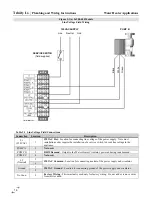
Page 18: ... Tank Demand Input requiring closure of terminals 7 and 10 to initiate a demand for DHW Switch made via isolated end switch dry contact from the storage tank thermostat Aquastat Or optional Tank Sensor P N 84632 see Appendix A NOTICE Tank Sensor when operating in a cascade system the water heater controls do not support the use of a tank sensor a tank thermostat switch must be used OD SENSOR 8 Out...

Page 19: ...at Or optional Tank Sensor P N 84632 see Appendix A OD SYS SENSOR 12 Outdoor Temperature Sensor Not applicable for Water Heater Applications System Water Temperature Not applicable for Water Heater Applications TOD 13 Time of Day Night Time Setback Input requiring closure of terminals 13 and 14 to initiate TOD setback setting Switch is made using an isolated end switch dry contact using a timer BA...

Page 20: ...minals to any other terminal other than terminals 4 5 and or 6 LIM CH1 and CH2 LL via an isolated end switch dry contact Failure to follow these instructions may damage the unit Fuse 24VAC Trinity Lx150 400 models are equipped with a blade style 2 Amp fuse to protect the internal transformer located within the slide out control panel box Figure 3 2 All Models Lx150 400 shown Low Voltage Field Wiri...

Page 21: ...Water Heater Applications Plumbing and Wiring Instructions Trinity Lx 21 NOTES ...

Page 22: ...Trinity Lx Plumbing and Wiring Instructions Water Heater Applications 22 NOTES ...

Page 23: ...NOTES ...

Page 24: ...NY Thermal Inc 65 Drury Cove Road Saint John NB E2H 2Z8 Canada Technical Assistance 1 800 688 2575 Website www nythermal com Fax 1 506 432 1135 ...

Reviews: