background image

Owner’s Manual

1111 W. 35th Street  Chicago, IL 60609 USA

Customer Support: (773) 869-1234  • www.tripplite.com

Important Safety Instructions

2

Mounting

3

Connection

4

Basic Operation

6

Storage and Service

10

Español

Copyright ©2002 Tripp Lite. All rights reserved. SmartPro

®

is a registered trademark of Tripp Lite.

SmartPro

®

1U Rackmount

120V Input/Output UPS Systems • Standby • Intelligent

Models: 750—1000 VA

13

Battery Replacement

10

Specifications

11

200210187 Smart 700-1000 RM1U Owner’s Manual 93-2102.qxd  11/1/2002  9:50 AM  Page 1

Summary of Contents for 1000 VA

Page 1: ...Basic Operation 6 Storage and Service 10 Español Copyright 2002 Tripp Lite All rights reserved SmartPro is a registered trademark of Tripp Lite SmartPro 1U Rackmount 120V Input Output UPS Systems Standby Intelligent Models 750 1000 VA 13 Battery Replacement 10 Specifications 11 200210187 Smart 700 1000 RM1U Owner s Manual 93 2102 qxd 11 1 2002 9 50 AM Page 1 ...

Page 2: ...rance Equipment Connection Warnings Do not use Tripp Lite UPS Systems for life support applications in which a malfunction or failure of a Tripp Lite UPS System could cause failure or significantly alter the performance of a life support device Do not connect surge suppressors or extension cords to the output of your UPS This may damage your UPS and will void both the surge suppressor and UPS warr...

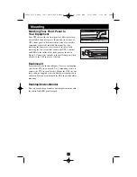
Page 3: ...Figure 1 Connect the controls to the new front panel then attach it to the UPS in place of the first Rackmount Position brackets as shown in Figure 2 to serve as mounting ears for the UPS in your rack Use 4 mounting screws to connect the UPS to each bracket Mount the UPS in your rack with user supplied screws and hardware appropriate to your rack Have an assistant hold the UPS in position while mo...

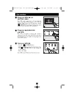
Page 4: ...uipment into your UPS Your UPS is designed to support only computer equipment You will overload your UPS if you connect household appliances laser printers or surge suppressors to the UPS s Outlets Turn your UPS ON Press the POWER button Hold the button for a moment until you hear a beep The POWER LED will stop flashing and be on constantly Release the button Your UPS is now ON and its AC outlets ...

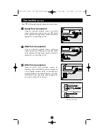
Page 5: ...s operating system EPO Port Connection Using the RJ 11 cable provided connect the Emergency Power Off EPO port of your computer to a user supplied normally closed or normally open switch according to the circuit diagram at the right The EPO port is not a phone line surge suppressor do not connect a phone line to this port 1 SMART1000RM1U SNMP CONFIG 1 EPO NORM DELAY SEE MANUAL ACC SLOT SMART1000RM...

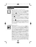
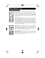
Page 6: ...T mode to warn you that AC power has failed The second the OVERLOAD alarm emits short rapid beeps when the UPS is in INVERT mode if the total power draw of connected equipment exceeds the UPS s output capacity to warn you to reduce the load The third the LOW BATTERY alarm emits a constant beep when the UPS is in INVERT mode and its batteries are very nearly depleted to warn you that connected equi...

Page 7: ...d its battery is discharging If the light is flashing red your UPS battery is running out of power you should save files and shut down your equipment immediately OUTPUT LOAD This multicolored light shows how heavy your UPS s load is Steady green indicates a light load steady yellow a medium load When the light is red your UPS is supporting a load above 85 of its capacity If the red light begins fl...

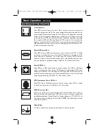
Page 8: ... remotely monitor and manage power and automatically save open files and shut down equipment during a blackout See Connection section Smart USB Port Your UPS has a USB port that may be used to connect the UPS to a USB port on any workstation or server It uses USB protocol to communicate UPS status and power conditions Use with Tripp Lite cabling and PowerAlert Software to remotely monitor and mana...

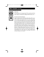
Page 9: ...tch to battery too often draining its battery reserves You may be able to reduce how often your UPS switches to battery due to waveform distortion or brownouts by experimenting with different settings for this dial As the dial is turned clock wise the UPS becomes more tolerant of variations in its input power s AC wave form and reduces the voltage point at which it switches to battery NOTE The fur...

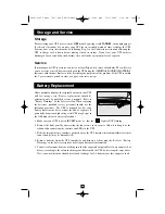
Page 10: ...nnel Refer to Battery Warnings in the Safety section When replacing the batteries qualified service personnel should use the following procedure The UPS is designed for hot swap battery replacement but to reduce the risk of exposure to potentially dangerous high voltages the UPS may be put in the OFF mode before battery replacement 1 Make sure your UPS is not in INVERT mode i e that the light is N...

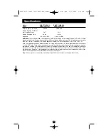
Page 11: ... the limits for a Class A digital device pursuant to part 15 of the FCC Rules These limits are designed to provide reasonable protection against harmful interference when the equipment is operated in a commercial environment This equipment generates uses and can radiate radio frequency energy and if not installed and used in accordance with the instruction manual may cause harmful interference to ...

Page 12: ...12 200210187 Smart 700 1000 RM1U Owner s Manual 93 2102 qxd 11 1 2002 9 50 AM Page 12 ...

Page 13: ...básica 18 Almacenamiento y servicio 21 Copyright 2002 Tripp Lite Todos los derechos reservados SmartPro es una marca comercial registrada de Tripp Lite SmartPro 1U para montaje en rack Sistemas UPS 120 V entrada salida En reserva Inteligentes Modelos 750 1000 VA Reemplazo de batería 21 Especificaciones 22 200210187 Smart 700 1000 RM1U Owner s Manual 93 2102 qxd 11 1 2002 9 50 AM Page 13 ...

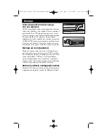
Page 14: ... vida Advertencias sobre la conexión de equipos No use sistemas UPS Tripp Lite para aplicaciones de soporte de vida en las que un funcionamiento defectuoso o una falla de un Sistema UPS pudiera causar la falla o una alteración importante en el funcionamiento del dispositivo de soporte de vida No conecte supresores de sobretensiones ni cordones de extensión a la salida de su UPS Esto puede dañar el...

Page 15: ...nel al UPS en el lugar del anterior Montaje en rack bastidor Ubique los soportes como se muestra en la Figura 2 para que sirvan como orejas de montaje para el UPS en el rack Use 4 tornillos de montaje y arandelas para conectar el UPS a cada soporte Monte el UPS en el rack con tornillos y accesorios suministrados por el usuario que sean apropia dos para el rack Con la ayuda de alguna persona manten...

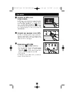
Page 16: ...iseñado para dar soporte solamente a equipos de computadora Si conecta electrodomésticos impresoras láser o supresores de sobretensiones a las salidas del UPS lo sobrecargará Encienda su UPS ON Pulse el botón POWER ENERGÍA Sostenga presionado el botón por un momento hasta que escuche un pitido el LED POWER ENERGÍA dejará de brillar en forma inter mitente y estará constantemente encendido Suelte el...

Page 17: ...nexión de puerto EPO Usando el cable RJ 11 proporcionado conecte el puerto EPO Desconexión de emergencia de su com putadora con un interruptor normalmente cerrado o normalmente abierto suministrado por el usuario de acuerdo con el diagrama de circuito de la derecha El puerto EPO no es un supresor de sobretensiones de línea telefónica no conecte una línea telefónica con este puerto 1 SMART1000RM1U ...

Page 18: ...mera la alarma INVERT emite cuatro pitidos cortos cada diez segundos cuando el UPS está en modo INVERT para advertirle que ha fallado el suministro de corriente alterna La segunda la alarma OVERLOAD SOBRECARGA emite pitidos cortos y rápidos cuando el UPS está en modo INVERT si la potencia total del equipo conectado excede a la capacidad de sali da del UPS para advertirle que reduzca la carga La te...

Page 19: ...e está descargando Si la luz es roja y brilla en forma intermitente la batería de su UPS se está agotando debe guardar sus archivos y apagar su equipo de inmediato OUTPUT LOAD CARGA DE SALIDA Esta luz multicolor le indica cuan pesada es la carga de su UPS Una luz verde constante indica una carga ligera y una luz amarilla constante indica una carga mediana Cuando la luz es roja su UPS está soportan...

Page 20: ...la energía en forma remota así como para guardar automáticamente archivos abiertos y apagar equipos durante una falla del servicio eléctrico Vea la sección Conexión Puerto Smart USB Su UPS tiene un puerto USB que puede ser usado para conectar el UPS con un puerto USB en cualquier estación de trabajo o servidor Usa el protocolo USB para comunicar el estado y las condiciones de energía del UPS Úselo...

Page 21: ...ma de onda pueden causar que el UPS conmute a ali mentación por baterías con demasiada frecuencia agotando sus baterías de reser va Es posible que se reduzca la frecuencia con que su UPS conmuta a baterías debido a la distorsión de la forma de onda o a bajas de voltaje experimentando con diferentes ajustes para este dial A medida que el dial es girado en el sentido de las agujas del reloj el UPS s...

Page 22: ...Seguridad Al reemplazar las baterías el personal de servicio calificado debería usar el siguiente procedimiento El UPS está diseñado para el reemplazo de baterías en operación sin embargo para reducir el riesgo de exposición a altos voltajes potencialmente peligrosos el UPS puede ser puesto en modo OFF antes del reemplazo de baterías 1 Asegúrese de que su UPS no esté en modo INVERT es decir que la...

Page 23: ...o cumple con los límites designados para un dispositivo digital de la Clase A de acuerdo con la parte 15 de las Regulaciones de FCC Estos límites se diseñaron para proporcionar protección razonable contra interferencias perjudiciales cuando la unidad es operada en entornos comerciales Este equipo genera utiliza y puede radiar energía de radio frecuencia y si no es instalado y utilizado de acuerdo ...

Page 24: ...1111 W 35th Street Chicago IL 60609 USA Customer Support 773 869 1234 www tripplite com 200210187 93 2102 200210187 Smart 700 1000 RM1U Owner s Manual 93 2102 qxd 11 1 2002 9 50 AM Page 3 ...

Reviews: