background image

Tritex Multigauge 5700 Datalogger Ultrasonic Thickness Gauge                         www.tritexndt.com

Page

simple . accurate . robust

www.tritexndt.com

Ultrasonic Thickness Gauge

Multigauge 5700

Datalogger

User Manual

Summary of Contents for Multigauge 5700

Page 1: ...Tritex Multigauge 5700 Datalogger Ultrasonic Thickness Gauge www tritexndt com Page simple accurate robust www tritexndt com Ultrasonic Thickness Gauge Multigauge 5700 Datalogger User Manual ...

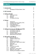
Page 2: ...re of Probes 9 5 Getting to know your Multigauge 5700 10 5 1 Switching the Gauge On 11 5 2 Switching the Gauge Off 11 5 3 Automatic Shutoff 11 5 4 Automatic Display Dimming 11 5 5 Measurement Hold Feature 11 6 Navigating the Menus 12 6 1 Entering the Menus 12 6 2 Definition of Menu Items 13 6 3 iProbe 14 6 4 Setting the Calibration 16 6 5 Velocity Table approximate values 17 6 6 Measuring 18 6 7 S...

Page 3: ...2 8 3 5 Properties Tab 48 8 3 6 Diagnostics Tab 49 9 Using the Multigauge 5700 50 9 1 How Multiple Echo Works 50 9 2 Echo Strength Indicator 51 9 3 Precautions when Measuring 51 10 Help 53 10 1 Gauge fails to switch on 53 10 2 Difficult to obtain readings 53 10 3 Gauge displays up to three ascending bars 53 10 4 Standing readings are displayed when not measuring 53 10 5 Gauge measures correctly on...

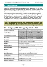
Page 4: ...ons Probe Measurement Range Probe Sizes Resolution 0 1 mm 0 005 or 0 05 mm 0 002 Accuracy 0 1 mm 0 005 or 0 05 mm 0 002 Display Multi character Colour LCD Storage Capacity Up to 895 files each file containing up to 100 records Each record contains up to 250 measurements Data Transmission RF Transceiver 2 4GHz Batteries 3 x disposable AA alkaline batteries or rechargeable NiMH NiCD Battery Life 20 ...

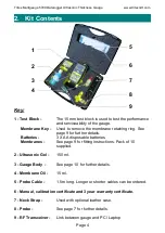
Page 5: ...ies 3 X AA disposable batteries Membranes See page 9 for fitting instructions Pack of 10 supplied 2 Ultrasonic Gel 150 ml 3 Gauge Body See page 10 for further details 4 Membrane Oil 15 ml 5 Probe Cable 1 5m long Longer or shorter cables can be ordered 6 Manual calibration certificate and 3 year warranty certificate 7 Neck Strap Used with optional leather case 8 Probe See page 7 for further details...

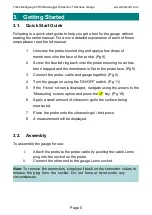
Page 6: ...e face Pg 9 3 Connect the probe cable and gauge together Pg 5 4 Turn the gauge on using the ON OFF switch Pg 11 5 If the Home screen is displayed navigate using the arrows to the Measuring screen option and press the key Pg 18 6 Apply a small amount of ultrasonic gel to the surface being measured 7 Place the probe onto the ultrasonic gel test piece 8 A measurement will be displayed 3 2 Assembly To...

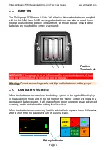
Page 7: ...uge is to be left unused for an extended period of time then the batteries must be removed prior to storage Warning Do not mix rechargeable and disposable batteries in the gauge 3 4 Low Battery Warning When the batteries become low the battery symbol in the right of the display in measurement mode and in the top right on the Home screen will indicate a decrease in battery power It will change from...

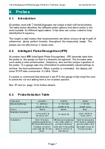
Page 8: ...mber frequency size and the unique signature of the probe The gauge uses this information to automatically adjust settings to achieve the best performance When a probe is connected the display will show IPR Probe connected 2 MHz 13mm If a probe is connected that does not have IPR the gauge will prompt the user to select the correct setting from a list of probe options See iProbe on page 14 for fur...

Page 9: ...onitored and checked at regular intervals Normal Temperature Membranes Standard membranes allow measurements to be taken on hot surfaces up to a maximum of 70 C 158 F High Temperature Membranes Teflon membranes are available for measurements on hotter surfaces In this case measurements can be taken on surfaces up to 150 C 302 F Care should be taken that the probe does not overheat The probe should...

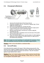
Page 10: ...he face of the probe 4 Do not use too much vii Screw the knurled ring 1 back onto the probe 4 whilst applying pressure on the membrane 2 with the thumb to expel any air from behind the membrane Note Do not apply too much membrane oil underneath the membrane Once fitted the membrane should be flat with no air bubbles trapped behind Warning Never use a probe without a membrane fitted 4 6 Care of Pro...

Page 11: ...com Page 10 da ta lo gg er 5700 Probe Cable Connector Back Battery Compartment 5 Getting to know your Multigauge 5700 Front Up Selection 5 ON OFF Button 3 Down Selection 9 OK Enter 4 Menu 8 Colour LCD Display Top Right Selection 7 Left Selection 2 Option Key 2 6 Option Key 1 1 ...

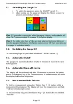
Page 12: ...he Gauge Off To switch the gauge off press and release the ON OFF switch 3 5 3 Automatic Shutoff The gauge will automatically shut off after 8 minutes of inactivity to save battery power 5 4 Automatic Display Dimming The display will dim automatically after 30 seconds to preserve the battery power Pressing any key or the commencement of measurements will return the display to its normal brightness...

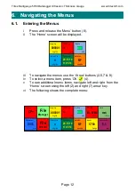
Page 13: ...itional menu items navigate left and right from the Home screen using the left 2 and right 7 arrow key vi The following shows the complete menu Datalink RF Enabled Measuring mm Battery 4 4V Select File Logfiles 4 Time Date 09 15 10 11 05 14 000001 Logfile Logging Datalink RF Enabled 5700 Gauge About Measuring mm Battery 4 4V Units V3 51b mm Resolution mm 0 1 iPROBE 2 MHz 13mm 5915 m s Calibration ...

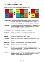
Page 14: ...tes Also the creation of new templates Logging Shows the measurements being stored Select File Allows the selection of file to which measurements are to be added Measuring Displays the measurements being taken by the gauge Time Date Displays the current time and date Battery Displays the remaining battery life The green changes to amber when the battery is getting low and then changes to red when ...

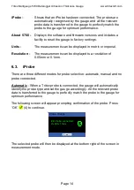
Page 15: ...ic or imperial Resolution The measurements can be displayed to a resolution of 0 05mm or 0 1mm 6 3 iProbe There are three different modes for probe selection automatic manual and no probe connected Automatic When a Tritex probe is connected the gauge will automatically identify the probe type and set the gauge accordingly All the relevant probe data is transferred to the gauge to perfectly match t...

Page 16: ... and then use the Up 5 and Down 9 arrow buttons to select from the following displayed list Press Option Key 2 6 to save the selection The selected probe will be displayed at the bottom of the screen in measurement mode The above menu can also be displayed by selecting iProbe from the Home screen menu Note This feature only shows in the menu if a compatible probe other than a Tritex probe with IPR...

Page 17: ...here are two methods of changing the calibration Either adjust the velocity of sound setting according to the metal being measured or adjust the the gauge to a known thickness of metal Gauges are supplied with the calibration set to mild steel at approximately 5900 m s 0 2323 in µs This may vary according to the properties of the supplied 15 mm test block material Note The calibration does not nee...

Page 18: ...ongly dependent on the alloy heat treatment manufacturing and processing and are therefore only approximate standard values They are given here as a guide only Reference Mathies Klaus 1998 Thickness Measurement with Ultrasound Berlin German Society of Nondestructive Testing Material Velocity m s Velocity in µs Aluminium Rolled Duraluminium 6200 6360 6420 6320 0 2441 0 2504 0 2528 0 2488 Bronze 5 P...

Page 19: ... 7 9 Use the Definition of Menu Items on pg 13 as a guide ii Press OK 4 iii Use the Up 5 and Down 9 buttons to select the required units iv Press Option Key 2 6 the gauge will save the new units and return to the Home screen v Pressing the Option Key 1 1 will quit the units setup and return to the Home screen 6 8 Battery The battery voltage is displayed in the Home screen See Chapter 3 page 6 for ...

Page 20: ... the gauge will save the new resolution and return to the Home screen v Pressing the Option Key 1 1 will quit the resolution setup and return to the Home screen 6 10 Coating Plus Coating Plus mode is used to measure metal thickness when thick coatings up to 20 mm exist Normal measurement mode will ignore coatings up to approximately 6 mm In both modes the actual thickness of coating that can be ig...

Page 21: ...Option Key 1 1 will quit the CoatingPLUS setup and return to the Home screen vii If selected the icon CP will be shown in the right of the display in measurements mode 6 11 About 5700 Entering this menu feature displays the gauge software and firmware versions It also allows the gauge to be returned to Factory Settings as follows i Navigate to About 5700 on the Home screen using the Arrow keys 2 5...

Page 22: ...on Key 2 6 the gauge will save the new time and date and return to the Home screen vi Pressing the Option Key 1 1 will quit the Time Date setup and return to the Home screen 6 13 Enabling and disabling the Datalink i Navigate to Datalink RF on the Home screen using the Arrow keys 2 5 7 9 Use the Definition of Menu Items on pg 13 as a guide ii Press OK 4 iii Use the Up 5 and Down 9 buttons to selec...

Page 23: ...of Menu Items on pg 13 as a guide ii Press OK 4 iii Use the Up 5 and Down 9 buttons to select the required option for the list below iv Press either Option Key 1 1 or Option Key 2 6 the gauge will return to the Home screen There are three options a Create a new file using a Wizard b Create a new file using a Template list c Create a new Template Note The procedure for creating a New File or New Te...

Page 24: ... or more records each with a different number of Readings 2 Grid Stores measurements in a grid format where the number of X and Y coordinates are selected This Grid should be selected if measurements are to be first taken along the Y axis 3 Grid Stores measurements in a grid format where the number of X and Y coordinates are selected This Grid should be selected if measurements are to be first tak...

Page 25: ...er of Records using the Left 2 and Right 7 buttons 2 Press OK 4 3 Select the number of Readings in each Record using the Left 2 and Right 7 buttons 4 Press OK 4 5 Confirm the File settings 6 Press OK 4 to save the File as the File number allocated File wizard step 3 of 5 Records File type BACK QUIT NEXT Variable String How many Records in this File 2 min 2 max 100 File wizard step 4 of 5 Readings ...

Page 26: ...er Grid or Grid are chosen The following appears Select the type of Grid Record that is required Single One Record containing a Grid of Readings Multiple Two or more Records each containing a Grid with the same dimensions Variable Two or more Records each containing a Grid with differing dimensions File wizard step 2 of 3 Multiple 2 Grids Variable 2 Grids Select Grid Record multiple Single 1 Grid ...

Page 27: ...d step 4 of 4 File type BACK QUIT NEXT Multiple Grid 4 Rows Columns 5 max 16 max 16 How many Rows Columns in this Record Create this File File type BACK QUIT OK Multiple Grid Records in File 4 000005 Rows Record 2 Columns Record 5 Variable String 1 Select the number of Records using the Left 2 and Right 7 buttons 2 Press OK 4 3 Select the number of Rows Columns in the first Record using the Left 2...

Page 28: ...Up 5 and Down 9 buttons to select New File using Wizard ii Press OK 4 iii The following screen will appear iv Use the Up 5 and Down 9 buttons to select the required template v Press OK 4 vi The gauge will show the Logfile screen See page 29 Select Template Template of 1 2 Up PgUp Down PgDn 01 SingleString R10 02 SingleGrid R4C5 QUIT BACK OK ...

Page 29: ...ress Option Key 1 1 to Quit back to the Home Screen at any time vi Press the Option Key 2 6 to display more details about each File vii Press OK 4 once the required file is highlighted viii A brief description of the File is displayed As some Files contain more than one record the user can select which Record is to be used at this point by using the Left 2 and Right 7 buttons ix Press OK 4 x The g...

Page 30: ...re is where the measurement will be stored when the measurement is logged v The measurements are displayed in the top right corner of the screen vi Different squares can be selected by using the Arrow keys 2 5 7 9 Measurements can be re stored by positioning the highlighted square over a previous measurement and logging the new measurement vii When the highlighted square is in the required positio...

Page 31: ...e the Up 5 and Down 9 buttons to select the required option A Show File Summary Lists the total number of Files number of completed Files number of incomplete Files and the number of untouched Files B Delete All Files Deletes ALL Files on the gauge A warning is displayed asking the user for confirmation C Delete Last File Deletes the last File on the gauge A warning is displayed asking the user fo...

Page 32: ...dows Tritex Communicator may require Microsoft NET Framework 4 to be installed on your computer If this is not already installed it can be manually installed from the Communicator Installation DVD The following warning will be displayed to indicate this Note you may require administrator privileges in order to install software on your computer The hardware interface requires a spare USB port The i...

Page 33: ...ck to launch the program from the Start menu Start All Programs Tritex Communicator Tritex Communicator ii The program will launch and after about 5 seconds a warning will popup which indicates that the program has not yet found a Tritex gauge connected iii Click the OK button to remove this popup iv Set the serial COM port number to match the number obtained during the installation of the USB Tra...

Page 34: ... 33 a Click File Settings b Use the drop down selector to choose the required COM port c Click OK v Turn the gauge on after a few seconds Tritex Communicator will begin receiving measurement and status data from the gauge and the lost link message in the Measurement tab will disappear ...

Page 35: ...is run 8 3 1 Introduction Tritex Communicator has a main menu bar and a matching icon menu toolbar below The main display area presents the user with a tabbed interface which separates the Measurement Status and Control functions of the gauge 1 Measurement Tab For simply viewing the measurements received from the gauge and calibrating if required 2 Datalogging Tab For viewing and storing measureme...

Page 36: ... The units correspond to the measurement units selected i e metres sec for mm or inches microsecond for inch B Calibration Measurement calibration can be carried out from the Measurement tab by clicking on Gauge Calibration Enable menu item or by clicking on the Calibration icon A Calibration Slider Control will appear in the measurement area With the gauge measuring on a sample of test material o...

Page 37: ...easurements to be stored in a String Grid or a combination of both A Free Logging Free Logging allows measurements to be stored directly on the PC when the gauge is within range and measuring Measurements are freely added to a flexible list which is a String of Readings up to 999 in length Measurements are added to the list by clicking on the button The newest readings are added to the top of the ...

Page 38: ...ete the entire current list of readings or click Cancel to return to Free Logging with the current list unchanged Any individual reading can be deleted from the list Click to highlight the reading then click the Clear Selection button The selected reading will disappear from the list and all newer readings will be renumbered Any individual comment can be edited or a previously empty comment can be...

Page 39: ... tab separated values to allow convenient opening in other programs such as Microsoft Excel if required The file can be saved at any time and later re opened to resume logging by clicking File Open If the current list has not been saved you will be prompted to cancel opening the file to allow it to be saved first Click Cancel to decline opening a file and return to the original unsaved list or cli...

Page 40: ...our template files ttx c Select and open the required template ii Open an Existing File to Continue a Previous Session To open an existing file ensure the Datalogging tab is selected and click File Open file If the current list has not been saved you will be prompted to cancel opening the file to allow it to be saved first Click Cancel to decline opening a file and return to the original unsaved l...

Page 41: ...ork down columns Horizontal work along rows left to right Template Shows the most recent file path name after either saving or opening a file or template b Grid Collection or String Collection box The file structure consists of 1 to 100 Strings of Readings or 1 to 100 Grids of Readings Click on the or buttons to step through the collections The number of grid or string collections is always displa...

Page 42: ...ly move the highlighted cell to a new position Grid Collection Horizontal Working Axis When is clicked the highlighted cell will step left to right across the current row When the end of the row is reached the highlight jumps back to the start of the next row below the current row Grid Collection Vertical Working Axis When is clicked the highlighted cell will step down the current column When the ...

Page 43: ...into Communicator software The Files are listed on the right hand side along with their filename whether they have been completed and their File number ii Upload Selected Uploads a file to the gauge iii Delete All Files Deletes all files on the gauge A warning will be displayed asking for confirmation prior to deleting all the files iv Delete Last File Deletes the last file created on the gauge Sh...

Page 44: ...ed Once the template has been created it can be reused for each new datalogging location Template File Structures There are six templates available 1 Single String Fixed Length Ÿ A single string of readings Ÿ The length of the string number of readings is specified in the template 2 Multiple String Fixed Lengths Ÿ A set of strings of readings Ÿ The number of strings in the set is specified in the ...

Page 45: ... the set is specified in the template Ÿ The dimensions number of rows number of columns of every grid are the same Ÿ These dimensions are specified once during template generation 6 Multiple Grid Variable Dimensions Ÿ A set of grids of readings Ÿ The number of grids in the set is specified in the template Ÿ The dimensions number of rows number of columns of each grid can be different Ÿ The dimensi...

Page 46: ...ontal sets for measurements to be taken across rows b Vertical sets for measurements to be taken down columns iv Select the number of records of Strings or Grids in this template The options are either Single or Multiple If Multiple is selected the quantity selector will become active a Use the up or down arrows to select between 2 to 100 b The template dimensions can be set to all the same length...

Page 47: ...Grid Records String 1 Select the length of each String using the up and down arrows to set the value from 1 to 100 Grid 1 Adjust the Vertical depth of Grid number 1 using the up and down arrows to set the value from 1 to 100 2 Adjust the Horizontal width of Grid number 1 using the up and down arrows to set value from 1 to 30 ...

Page 48: ... named at this stage then they can be later edited when the template is opened ii If the Strings or Grids have different lengths then the number of vertical and horizontal measurement points must be set in at each stage Also a name can be optionally added at each step iii Use the and keys to toggle between the different records to make any changes iv When finished click on Done proceed to Step 3 b...

Page 49: ...tings Measurement settings which can be changed i Units click on or button to change the measurement units The following text boxes will change a Units text box b Resolution text box c Measurement Calibration fields ii Resolution click on or button to change the display resolution a mm Resolution will switch between 0 05 mm and 0 1 mm b inch Resolution will switch between 0 002 inch and 0 005 inch...

Page 50: ...r this sample b Calibration by Velocity When a suitable test sample is unavailable calibrate the gauge by adjusting the Velocity of Sound to an appropriate value see the velocity table in the gauge manual 8 3 6 Diagnostics Tab Diagnostics should not normally be required when using Tritex gauges the information is provided to check the correct performance of the gauge and link The only control prov...

Page 51: ...d pulse travels though both the coating and the metal and reflects from the back wall The returned echo then reverberates within the metal with only a small portion of the echo travelling back through the coating each time The timing between the small echoes gives us the timing of the echoes within the metal which relate to the metal thickness The returned echoes need not be consecutive as the gau...

Page 52: ...ed should be free from dirt or debris It may be necessary to clean or brush the surface prior to taking measurements qEnsure plenty of ultrasonic gel is used between the probe and the material to eliminate any air pockets Air is the enemy of ultrasound and it is essential that couplant exists to form a path for the ultrasonic signal qA membrane should be correctly fitted to the probe qPlace the pr...

Page 53: ...receive echoes from the back wall qEnsure the coating is not layered or does not contain foreign objects in its construction Layered coatings cause reflections at the layer interface This seriously weakens the strength of the ultrasound and may prevent it from travelling all the way through The same applies to foreign objects which can deflect the ultrasound path or prevent the ultrasound from pas...

Page 54: ... selected Select the correct probe see pg 7 Check the probe membrane is properly fitted with membrane oil applied and no trapped air present Refit or replace the membrane see pg 9 Check the probe lead and gauge are all connected together correctly and securely Re connect as necessary see pg 5 Check the serviceability of the probe and lead Contact Tritex NDT for replacement items see pg 58 Check th...

Page 55: ...n Measuring Ensure the coating is solidly adhered to the surface See pg 51 Precautions When Measuring Ensure the coating is not layered or contains foreign objects in its construction See pg 51 Precautions When Measuring Some types of casting may cause problems for ultrasonic gauges See pg 51 Precautions When Measuring 10 6 Communication lost between gauge and PC Laptop Advice Action Check the RF ...

Page 56: ...e fully RoHS compliant which means that we do not use hazardous substances and materials at any stage of manufacture Lead cadmium mercury and other such materials used in electronic equipment are not present in Tritex products RoHS compliance is already law in the United Kingdom and European Union and will soon be adopted in other countries seeking to protect the planet for future generations At T...

Page 57: ...nti static wipe Never use abrasives solvents or other cleaning products as this will damage the instrument Do not soak the gauge with water or other liquids 11 6 Warranty Tritex products are guaranteed against defects in material and or workmanship for a period of 3 years from date of delivery Any equipment that may be defective should be returned carriage paid direct to Tritex or to their approve...

Page 58: ...r through your local agent Before you return your gauge Check through the troubleshooting guide on page 53 If this does not solve the problem we can sometimes give advice over the phone When returning the gauge If after troubleshooting the gauge is still faulty then you will need to return your gauge for repair Please package the complete kit in a suitable protective container and return to us at ...

Page 59: ...uge www tritexndt com Page 58 Telephone 44 0 1305 257160 Facsimile 44 0 1305 259573 E mail Sales tritexndt com Website www tritexndt com Address Unit 10 Mellstock Business Park Higher Bockhampton Dorchester Dorset DT2 8QJ United Kingdom 12 Contact Information ...

Page 60: ...tritexndt com Page 59 Tritex Sales 47 Issue 1 April 2014 simple accurate robust Tritex NDT Ltd Unit 10 Mellstock Business Park Higher Bockhampton Dorchester Dorset United Kingdom DT2 8QJ t 44 0 1305 257160 f 44 0 1305 259573 e sales tritexndt com w www tritexndt com ...

Reviews: