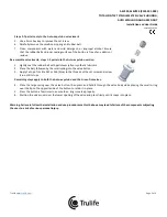
AEV320, MEV320 (P123-201-000)
TOTAL CONTACT STAINLESS STEEL VALVE HOUSING,
AUTO EXPULSION AND GREEN DOT
Installation and User Guide
19879-001 REV K
Trulife
Page 1 of 4
INTRODUCTION
The AEV320 and the MEV320 (P123-201-000) valves are intended for transfemoral prosthetic suction sockets. Both utilize a stainless
steel valve housing which is ideal for use with laminated socket materials.
The AEV320 valve insert has an automatic air expulsion function and a manual push button to release suction.
The MEV320 (P123-201-000) Green Dot valve has a push button to manually expel air and to release suction.
Both valve inserts are removable to allow use of a pull-sock for donning the socket.
Both are furnished with a valve key and the necessary components to embed the valve housing into the socket during the lamination
process.
Product Code
Description
AEV320
AUTO EXPULSION VALVE WITH TOTAL CONTACT STAINLESS STEEL HOUSING
MEV320 (P123-201-000)
GREEN DOT VALVE WITH
TOTAL CONTACT STAINLESS STEEL HOUSING
PRODUCT CONTENTS:
ITEM
QTY
PART #
DESCRIPTION
1
(AEV320)
1
AEV350i
AUTO EXPULSION VALVE INSERT
ASSEMBLY
1
(MEV320)
1
MEV350i
GREEN DOT VALVE INSERT
ASSEMBLY
2
1
19334-001
STAINLESS STEEL HOUSING
FABRICATION / ADDITIONALCOMPONENTS :
3
1
24437-001
SCREW, SIZE #8 X 1.25" LONG
4
1
24634-001
#10 FLAT WASHER
5
1
23974-001
VALVE PLUG
6
1
24785-001
O-RING, SIZE -116
7
1
19774-001
VALVE KEY ASSEMBLY (NOT SHOWN)
INSTALLATION AND USE
Recommended installation and use procedures must be followed for maximum safety and service life.
Socket Preparation:
1.
Sand a flat spot on the model at the determined valve location. Drill a 1/8” (3.2 mm) pilot hole in the center. Seal, cap and
bag model in the usual manner.
2.
Apply a disk of clear package sealing tape over the center of the pilot hole and puncture a hole through the tape and PVA.
3.
Ensure the o-ring is installed onto the valve plug.
4.
Thoroughly grease valve plug threads and o-ring with petroleum jelly, then screw firmly into valve housing. Wipe off excess.
5.
Fill the slight depression in the bottom of the valve housing against the internal face of the plug with clay.
6.
Attach the assembled valve housing and valve plug to the model at the pilot hole using the screw and washer provided.
Tighten down securely and remove excess clay that is forced out.
7.
Fill the remaining center hole in the valve plug with clay, making sure to cover the screw head and the slot.
8.
Lay up the socket and laminate in the usual manner.


