background image

1

© TrynEx International 2013
(REV C) F50766

Madison Heights, Michigan 48071
800-SALTERS
www.snowexproducts.com

CUSTOMER COPY

This Manual Must Be Read Before Operating The Equipment

Owner / Operator’s Manual

PWX-200 

Serial # 200959 and higher 

PWX-250 

Serial # 200959 and higher

Summary of Contents for SnowEx PWX-200

Page 1: ...F50766 Madison Heights Michigan 48071 800 SALTERS www snowexproducts com CUSTOMER COPY This Manual Must Be Read Before Operating The Equipment Owner Operator s Manual PWX 200 Serial 200959 and higher...

Page 2: ...15 Harness Diagram 16 Troubleshooting 17 Warranty 18 Key to Parts 19 Tank Assembly Parts Breakdown Model PWX 200 20 21 Model PWX 250 22 23 Pump Assembly Parts Breakdown Model PWX 200 PWX 250 24 25 Not...

Page 3: ...on SnowEx products WARRANTY Best in the industry hands down 2 years standard and now 5 year extended optional The benefits you are about to recognize are that of time money and effort We welcome you t...

Page 4: ...LERT YOU The Society of Automotive Engineers has adopted this SAFETY ALERT SYMBOL to pinpoint characteristics that if NOT carefully followed can create a safety hazard When you see this symbol in this...

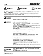
Page 5: ...e Before working with the equipment secure all loose fitting clothing and unrestrained hair Always wear safety glasses with side shields when servicing equipment Failure to do this could result in ser...

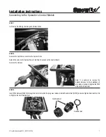
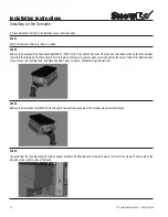
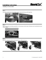
Page 6: ...s kit be installed by your SnowEx Dealer STEP 5 Remove the Cover of the Power Box STEP 1 Unplug the Spreader from all of the plugs on the Bumper STEP 2 Remove Spinner Drive Latch Pin STEP 3 Put Spinne...

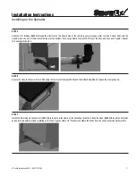
Page 7: ...rd Restraint STEP 7 Cut the Zip Tie holding the Orange and Green Wires STEP 8 Remove the Cord that connects to the Spinner Drive Detach the wires to the Spinner Power Cord from the studs on the Contro...

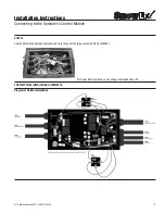
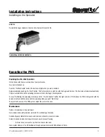
Page 8: ...Black Wire of the PWX Harness onto the GND Terminal Reinstall the Nut and Washer Tighten STEP 11 Reinstall the Spinner Harness The White Wire belongs on the Spinner Terminal the Black Wire belongs on...

Page 9: ...ng to the Spreader s Control Module Put Power Box Cover back on Leave Auger Extension Cover off STEP 14 Coil the Wires to the Relay back around and tie to the one of the large wires with Zip Tie F5020...

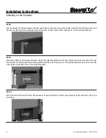
Page 10: ...he rails of the Sideframe The Tank should click into place The tank is in position when centered between the Corner Posts of the Sideframe and stays clicked into the Sideframe Bolt Mounting Rail in pl...

Page 11: ...Large Plastic Clamp F50577 over the hose and hose barb Tighten Repeat for Passenger Side tank STEP 6 Secure the Hose to the Lower Frame Rail using the four metal Clamps D7220 and the Driller Bolts D64...

Page 12: ...ning 1 2 Plastic Hose Clamp F50146 STEP 9 Mount Pump D5265 to the Rear Auger Extension Use the Pump Mounting Hardware Kit The Pump should be mounted so the head of the Pump faces rearward The Washers...

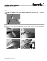
Page 13: ...ump into the Pre Wet Harness installed in Electrical Installation Use Dielectric Grease on the connection Route the Harness over the Auger Tube STEP 12 Mark a line 1 5 8 from the edge of the Trough Co...

Page 14: ...ut on and tighten Align the barb parallel with the angle of the Trough Cover STEP 14 Slide the Hose Assembly onto the Barbs just installed The 9 Hose should go to the Barb closer to the Hopper Use the...

Page 15: ...solution and the spreading material will mix in the Auger Discharge Tube To stop Pre Wetting the spreading material push the Pre Wet Enable button the light will turn off Otherwise the PWX is integra...

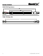
Page 16: ...TrynEx International 2013 REV C F50766 16 F50681 PWX Relay Wire F50679 PWX Pump Harness 8 00 Harness Diagram...

Page 17: ...SSIBLE CAUSE SOLUTION Pump doesn t run Loose electrical connections Blown fuse Pump seized Check all connections Replace fuse Replace pump Controller shut down Poor electrical connections Electrical s...

Page 18: ...be made to the dealer from where the product was purchased unless otherwise authorized by SnowEx SnowEx reserves the right to determine if any part is defective and to repair or replace such parts as...

Page 19: ...3 4 Male Thread D6951 Nozzle Body 11 16 16 UNM X 3 8 HB 90 D6988 9 Hose 3 8 X 9 PVC Clear D6988 8 Hose 3 8 X 1 X 8 PVC Clear D6988 12 Hose 3 8 X 1 X 12 PVC Clear D6989 42 Hose 1 2 X 42 PVC Clear D698...

Page 20: ...TrynEx International 2013 REV C F50766 20 Tank Assembly Parts Breakdown Model PWX 200 18 19 1 8 20 12 3 9 15 13 13 6 14 6 16 3 10 15 14 11 4 3 16 2 17 5 7 17...

Page 21: ...Pipe Plug 3 4 NPT 2 8 D6925 3 4 NPT x 1 2 NPT Reducer 1 9 D6989 42 Hose 1 2 X 42 PVC Clear 1 10 D6990 80 Hose 3 4 X 80 PVC Clear 1 11 D7220 Clamp 1 Rubber Coated 4 12 F50146 Hose Clamp Double Tooth Po...

Page 22: ...TrynEx International 2013 REV C F50766 22 Tank Assemblies Breakdown Model PWX 250 18 19 1 8 20 12 3 9 15 13 14 6 16 13 15 10 14 11 3 4 16 6 7 2 17 5 17...

Page 23: ...Plug 3 4 NPT 2 8 D6925 3 4 NPT x 1 2 NPT Reducer 1 9 D6989 45 Hose 1 X 45 PVC Clear 1 10 D6990 80 Hose 3 4 X 80 PVC Clear 1 11 D7220 Clamp 1 Rubber Coated 4 12 F50146 Hose Clamp Double Tooth Poly 3 8...

Page 24: ...nEx International 2013 REV C F50766 24 Pump Assembly Parts Breakdown Model PWX 200 PWX 250 8 18 7 19 16 12 11 13 13 17 15 10 13 3 9 13 6 1 2 4 5 14 8 18 7 19 16 12 11 13 13 17 15 10 13 3 9 13 6 1 2 4...

Page 25: ...948 Nut 10 32 Nylox Waxed Stainless 4 7 D6083 Relay 20 Amp 1 8 D6781 Nut 1 2 NPT Black Nylon 1 9 D6951 Nozzle Body 11 16 16 UNM X 3 8 HB 90 2 10 D6988 12 Hose 3 8 X 1 X 12 PVC Clear 1 11 D6988 8 Hose...

Page 26: ...TrynEx International 2013 REV C F50766 26 Notes...

Page 27: ...27 TrynEx International 2013 REV C F50766 Notes...

Page 28: ...131006...

Reviews: