background image

C

C

e

e

n

n

t

t

u

u

r

r

y

y


T

T

5

5

2

2

0

0

0

0

B

B

a

a

r

r

i

i

a

a

t

t

r

r

i

i

c

c


M

M

a

a

x

x

H

H

o

o

m

m

e

e

c

c

a

a

r

r

e

e


B

B

e

e

d

d

O

O

p

p

e

e

r

r

a

a

t

t

i

i

o

o

n

n


M

M

a

a

n

n

u

u

a

a

l

l

CENTURY MAX_T5200_V1.0

Summary of Contents for Century Max T5200

Page 1: ...C Ce en nt tu ur ry y T T5 52 20 00 0 B Ba ar ri ia at tr ri ic c M Ma ax x H Ho om me ec ca ar re e B Be ed d O Op pe er ra at ti io on n M Ma an nu ua al l CENTURY MAX_T5200_V1 0 ...

Page 2: ...is a true heavy duty bed that holds up to 1 000 lbs It is specially engineered and designed for Alzheimer residents or others with chronic impairments which will reduce their degree of independence in activities of daily living The T5200 is a fully electric adjustable bed The bed height head and foot angles functions are standard along with trendelenburg and reverse trendelenburg functions that ar...

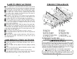
Page 3: ...e it can be seen at any moment ASSEMBLING PRECAUTIONS ASSEMBLING PRECAUTIONS L Split frame design frame with fully loaded electronics system requires minimum set up L Do not over tighten mounting hardware It will cause damage to mounting brackets L Be sure that bed side rails are properly attached on main frame before the patient is moved into the bed L Secure the caster locks in place to prevent ...

Page 4: ... case or pallet and examine deck and frame for shipping damage If damage is detected in shipping contact the freight company and file a damage claim Dispose of the removed packaging at your local recycling center Discard the wrapper and box separately Dispose of the end of life item at a clean point MAIN COMPONENTS MAIN COMPONENTS PRODUCT SPECIFICATION PRODUCT SPECIFICATION ...

Page 5: ...m wrench and two 19mm wrench Directions for Bed Placement A 15 foot electrical cord powers the bed so it should be positioned within access to a AC 110 Volt outlet Place the bed 12 from the wall to avoid damage during operation WARNING Make sure power cords are free of pinch points Results of Incorrect Setup If electrical cord is pinched in bed mechanisms the bed positioning may not function If yo...

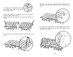
Page 6: ...and bolts on each end of the headframe on the receptacle holders set the nut and bolts on the side 2c Assemble the bolt washer and moon shape spacer in order according to the diagram below and attach the mattress stop bar onto the frame surface 2 The matterss stop bars are shipped cable tie on to both side of the frame remove them to install Below illustration shows headframe on the right and foot...

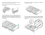
Page 7: ...3a First start with the foot frame pull out the ring grip quick release pins on two side of the receptacle tubes 3b Carefully set the mounting tubes on the board end down the receptacle tubes 3d Repeat the same process as the footboard for the headboard to complete the assembly 4 The two actuators on the foot frame were shipped unplunged they need to be plug into the junction box for the bed to fu...

Page 8: ... 19MM wrenches to tighten the bolt and nut in order to secure the swing bars on the top head of the section frame 4a The actuator plug are color coded plug the blue plug into the foot motor receptacles and the yellow into the hi lo receptacles ASSEMBLING SWING DOWN HALF BED SIDE RAILS Note Secure the caster locks in place to prevent the bed from moving 5a Raise the head frame to expose the holes o...

Page 9: ...Foot Section D Hi Low E Trendelenburg Reverse Trendelenburg F LED Night Light ON OFF L WARNING DO NOT exceed the maximum weight limit of Beds T5248 800 lbs T5254 T5260 1 000 lbs L WARNING Operation of this device with any part of the body in the frame can result in injury Do not place your arm or head in the frame while operating L WARNING Stand clear of device frame before operating L WARNING Rot...

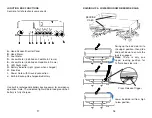
Page 10: ...S JUNCTION BOX FUNCTIONS Control of all of electronic components A Hand Pendant Control Panel B Head Motor C Foot Motor D Hi Low Motor installed on Foot Main Frame E Hi Low Motor installed on Head Main Frame F LED Night Light G Battery Indicator Light green when charged H Fuse Box I Power Cord with Ground connection J Built in Backup Re chargeable Battery Use built in rechargeable battery backup p...

Page 11: ...er storage or damages beyond Tuffcare control The evaluation will be solely determined by Tuffcare The warranty shall not apply to problems arising from normal wear or failure to follow instructions or if parts are not manufactured by Tuffcare or do not comply with original equipment specifications that are added to Tuffcare product THE FOREGOING WARRANTY IS EXCLUSIVE AND IN LIEU OF ALL OTHER WARR...

Reviews: