Gerätekurzbeschreibung
•
Übertragung von Stromsignalen
(0/4…20 mA)
•
IM35-11…-Hi…: einkanalig
IM35-22…-Hi…: zweikanalig
•
Nur bei Geräten mit „Ex“ in der Typen-
bezeichnung:
– Eigensicherer Ausgangskreis Ex ia,
– Anwendungsbereich nach ATEX:
II (1) G, II (1) D, II 3 G
– Zugelassen für Einbau in Zone 2
•
Bidirektionale HART®-Übertragung
•
Galvanische Trennung von Ausgangskreis
zu Eingangskreis und zur Versorgungs-
spannung
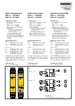
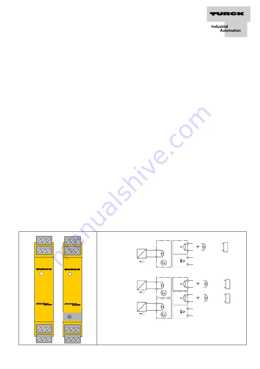
Klemmenbelegung (Fig. 2)
IM35-11…-Hi…:
1, 2
Stromausgang 1 (0/4…20 mA)
7, 10
Stromeingang 1 (0/4…20 mA)
11, 12
Betriebsspannungsanschluss
IM35-22…-Hi…:
1, 2
Stromausgang 1 (0/4…20 mA)
7, 10
Stromeingang 1 (0/4…20 mA)
4, 5
Stromausgang 2 (0/4…20 mA)
8, 9
Stromeingang 2 (0/4…20 mA)
11, 12
Betriebsspannungsanschluss
Leitungsanschluss durch anhebende Käfige
mit unverlierbaren Schrauben, Anschlussquer-
schnitt: ≤ 1 × 2,5 mm
2
, 2 × 1,5 mm
2
oder
2 × 1 mm
2
mit Ader-Endhüsen, max. Anzugsdreh-
moment: 0,5 Nm
LED-Anzeige (Fig. 1)
Pwr Betriebsbereitschaft
HART®-Ausgangstrenner
IM35-11…-Hi/24VDC
IM35-22…-Hi/24VDC
Fig. 1
Fig. 2
Séparateur de sortie HART®
IM35-11…-Hi/24VDC
IM35-22…-Hi/24VDC
HART® Output isolator
IM35-11…-Hi/24VDC
IM35-22…-Hi/24VDC
IM35-22…-Hi…
Short description
•
Transfer of current signals (0/4…20 mA)
•
IM35-11…-Hi…: 1 channel
IM35-22…-Hi…: 2 channels
•
Only on devices with “Ex” in
the type designation:
– Intrinsically safe output circuit Ex ia
– Area of application acc. to ATEX:
II (1) G, II (1) D, II 3 G
– Approved for installation in zone 2
•
Bidirectionally HART® transferring
•
Galvanic isolation of output circuit from
input circuit and from supply voltage
Terminal configuration (Fig. 2)
IM35-11…-Hi…:
1, 2
current output 1 (0/4…20 mA)
7, 10
current input 1 (0/4…20 mA)
11, 12
supply voltage connection
IM35-22…-Hi…:
1, 2
current output 1 (0/4…20 mA)
7, 10
current input 1 (0/4…20 mA)
4, 5
current output 2 (0/4…20 mA)
8, 9
current input 2 (0/4…20 mA)
11, 12
supply voltage connection
Connection via lifting cages with captive screws,
connection profile: ≤ 1 × 2.5 mm
2
, 2 × 1.5 mm
2
or 2 × 1 mm
2
with wire sleeves, max. tightening
torque: 0.5 Nm
LED indications (Fig. 1)
Pwr
power on
IM35-...Ex-Hi
24VDC
Zone 2: Do not dis-
connect when live!
+ 4
5
12
11 +
9
8 +
0/4...20 mA
HART
®
GN
I
P
110
10
7 +
110
+ 1
2
0/4...20 mA
HART
®
I
P
1
2
1
2
Power
HHT
0/4...20 mA
HHT
0/4...20 mA
Pwr
IM35-11…-Hi…
Description brève
•
Transmission de signaux de courant
(0/4…20 mA)
•
IM35-11…-Hi…: 1 canal
IM35-22…-Hi…: 2 canaux
•
Uniquement pour les appareils où
„Ex“ figure dans la désignation de type:
– Circuit de sortie à sécurité intrin. Ex ia
– Champ d‘application suivant ATEX:
II (1) G, II (1) D, II 3 G
– Certifié pour montage en zone 2
•
Transmission HART® bidirectionnelle
•
Séparation galvanique du circuit de sortie
et du circuit d‘entrée entre eux et par
rapport à la tension d‘alimentation
Raccordement des bornes (Fig. 2)
IM35-11…-Hi…:
1, 2
sortie de courant 1 (0/4…20 mA)
7, 10
entrée de courant 1 (0/4…20 mA)
11, 12
Raccordement de la tension de
service
IM35-22…-Hi…:
1, 2
sortie de courant 1 (0/4…20 mA)
7, 10
entrée de courant 1 (0/4…20 mA)
4, 5
sortie de courant 2 (0/4…20 mA)
8, 9
entrée de courant 2 (0/4…20 mA)
11, 12
Raccordement de la tension de
service
Raccordement du câble par des bornes à cage
levantes avec des vis imperdables, section raccor-
dable: ≤ 1 × 2,5 mm
2
, 2 × 1,5 mm
2
ou 2 × 1 mm
2
avec cosses, couple de serrage max.: 0,5 Nm
Visualisation par LED (Fig. 1)
Pwr
Tension de service
*) nur Ex-Gerät
only Ex device
seulement appareil de sécurité intrinsèque
*)
*)
*)

