background image

Jun 2017 


TP11KC-DX 

Two-Post Clear Floor  

‘Bi-Symmetric’ Automotive Lift 

11,000 lb. Capacity 

(2,750 lbs. Max per Arm)


Installation & Operation Manual


Summary of Contents for TP11KC-DX

Page 1: ...Jun 2017 TP11KC DX Two Post Clear Floor Bi Symmetric Automotive Lift 11 000 lb Capacity 2 750 lbs Max per Arm Installation Operation Manual...

Page 2: ...n 3 1 Site Selection 3 2 Surface Condition Foundation Anchoring 3 3 Tools Required 3 4 Installation Procedure 3 5 Hydraulic Scheme 4 Operation 4 1 Operation Instructions 4 1 1 Lift Preparation 4 1 2 L...

Page 3: ...E UNTIL YOU HAVE READ AND UNDERSTOOD THE WARNING INSTRUCTIONS 1 2 Important Information 1 Read this manual thoroughly before installing operating or maintaining this lift 2 This lift is designed for i...

Page 4: ...facturer s recommended pickup points Raise the lift until contact is made with the vehicle Make sure that the arms have properly engaged the vehicle before raising the lift to a working height 7 Keep...

Page 5: ...entative 19 The troubleshooting and maintenance procedures described in this manual can be done by the lift s owner employer Any other procedure should only be performed by trained lift service person...

Page 6: ...both asymmetrical symmetrical lifting configurations The TP11KC DX 2 post hydraulic lift consists of a fixed structural unit Crossbeam and Columns the mobile units Carriages and Lift Arms and the Hydr...

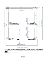
Page 7: ...DX Jun 2017 Fig 1 Front View Spec POWER UNIT MUST BE INSTALLED ON THE PASSENGER SIDE FAILURE TO DO SO CAN RESULT WITH INTERFERECE BETWEEN THE POWER UNIT AND SHORT SWING ARM THUS CAUSING DAMAGE TO POW...

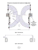
Page 8: ...8 TP11KC DX Jun 2017 Bi Symmetric Asymmetric Symmetric Configurations Fig 2a Top View Spec Fig 2b Base Size Spec NOTE Power Unit must be mounted on Passenger Side beside the long rear Swing Arm...

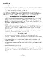
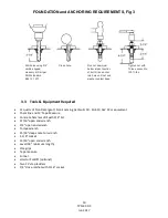
Page 9: ...full size base shim plates should be used Torque anchors to 130 ft lbs Shim thickness MUST NOT exceed 1 2 when using the 5 1 2 long anchors provided with the lift 5 If anchors do not tighten to 130 f...

Page 10: ...nut and B94 12 1977 washer contact base 3 3 Tools Equipment Required 12 quarts of Non Detergent Non Foaming Hydraulic Oil SAE 10 AW 32 or equivalent Chalk line and 12 Tape Measure Concrete hammer dril...

Page 11: ...column bases D Snap chalk lines parallel to the lift s centerline spaced 68 7 8 1 750 mm to the left and 68 7 8 1 750 mm to the right These lines represent the APPROXIMATE outside edges of the column...

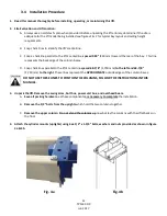
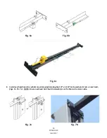
Page 12: ...late drill the anchor bolt holes for the Main side column Only Refer to FOUNDATION REQUIREMENTS ANCHORING TIPS ON PAGES 9 10 NOTE DO NOT ANCHOR OFF SIDE COLUMN AT THIS TIME C Install the anchor bolts...

Page 13: ...6a Fig 6b Fig 6c 8 Install overhead beam to cylinder mounts uprights using 2ea 1 2 x 1 3 4 bolts washers nuts on each end Figs 7a 7b 7c NOTE Ensure overhead Limit Switch Assembly is on the Main side...

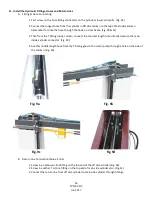
Page 14: ...preliminary layout as it is more important that the column be perpendicular to the floor and parallel to the other column C Install the anchor bolts and shim the base as described in Step 6 10 Equaliz...

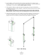
Page 15: ...nuts on top of each carriage top Use vise grips to hold the cable end but be very careful not to damage the threads NOTE CARRIAGES MUST REMAIN AT THE SAME COLUMN LOCK HEIGHT POSITION WHILE CABLES ARE...

Page 16: ...the T fitting inside column connect the shortest length hose directly down to the main inside cylinder connector Fig 9d 4 Another middle length hose from the T fitting goes to the motor pump through...

Page 17: ...lts and nylon nuts provided in the bolt box to Main side column B Connect the hose and the blue Return Line to the pump valve block as shown in Fig 10 13 Latch release cable wiring and accessories mou...

Page 18: ...ulley and support bracket on the top of the columns Fig 11c Fig 11c C Route and adjust the cable tension so that when the handle is pressed down both latch will be released D Put on the covers of the...

Page 19: ...iage to mate with the gears on the arms C Install the swing arms and pins Suggestion The longer arms go to the rear or drive in side of the lift and the short arms go to the front DON T FORCE THE GEAR...

Page 20: ...uty grease 17 Electrical Connection to POWER UNIT OVERHEAD LIMIT SWITCH A Have a certified electrician make the electrical connection to the power unit Use separate circuit for each power unit as show...

Page 21: ...red onto the locks the Latch Release Handle should NOT be capable of being pulled down Prior to lowering down carriages always raise up enough to free the latches then pull down the latch release hand...

Page 22: ...ulic Scheme 1 Reservoir Tank 2 Mesh Filter 3 Gear Pump 4 Motor 5 Relief Valve 6 Check Valve 7 Hydraulic Cylinder s 8 Manual Release Valve 9 Pressure Gauge not supplied Motor Power 3 HP 2 850 RPM Hydra...

Page 23: ...clear of all personnel before the vehicle be brought into the bay Swing arms out to full drive thru position 4 1 2 Loading Lift Swing arms under vehicle and position adapters at vehicle manufacturer...

Page 24: ...dividual axle weight does not exceed one half lift capacity Adapters are in secure contact with frame at vehicle manufacturers recommended lift point Vehicle is stable on lift The overhead switch bar...

Page 25: ...veral times for oil to penetrate joints Lubricate the four inside corners of the columns with heavy duty bearing grease With lift lowered check the hydraulic fluid level If necessary add oil as descri...

Page 26: ...26 TP11KC DX Jun 2017 5 Exploded View Parts List...

Page 27: ...bolt 2 15 165948T 01 015 nut 2 16 165948T 01 016 threaded pin 4 17 165948T 01 017 turning board 1 18 165948T 01 018 spring 2 2 19 165948T 01 019 latch 2 20 165948T 01 020 spring 1 2 21 165948T 01 021...

Page 28: ...ck 16 51 165948T 01 051 circlips 4 52 165948T 01 052 spring 4 53 165948T 01 053 gear shaft 4 54 165948T 01 054 small gear 4 55 165948T 01 055 cotter pin 4 56 165948T 01 056 anchor 12 57 165948T 01 057...

Page 29: ...77 11 165948T 01 077 11 guide belt ring 2 77 12 165948T 01 077 12 nut 2 77 13 165948T 01 077 13 base plate 2 77 14 165948T 01 077 14 spring 2 77 15 165948T 01 077 15 throttle valve 2 77 16 165948T 01...

Page 30: ...arm pin 4 95 165948T 01 095 circlips 4 96 165948T 01 096 slot 4 97 165948T 01 097 air hose 1 1 98 165948T 01 098 sponge bush 1 101 165948T 01 101 bolt 1 102 165948T 01 102 long screw slot 4 103 165948...

Page 31: ...ft D Problem Lift slowly settles down Possible cause Solution 1 Debris in check valve seat 2 Debris in lowering valve seat 3 External oil leaks 1 Clean check valve 2 Clean lowering valve 3 Repair exte...

Page 32: ...32 TP11KC DX Jun 2017 7 Power Unit Priming...

Page 33: ...33 TP11KC DX Jun 2017 8 Warranty...

Reviews: