background image

http://www.tyan.com


GA88-B8021 


Service Engineer’s Manual 


Summary of Contents for GA88-B8021

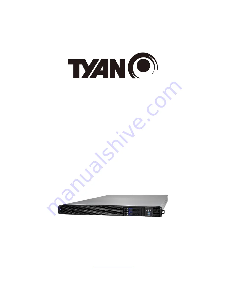
Page 1: ...1 http www tyan com GA88 B8021 Service Engineer s Manual ...

Page 2: ...ding liability or warranties relating to fitness for a particular purpose or merchantability MITAC retains the right to make changes to produce descriptions and or specifications at any time without notice In no event will MITAC be held liable for any direct or indirect incidental or consequential damage loss of use loss of data or other malady resulting from errors or inaccuracies of information ...

Page 3: ...se limits are designed to provide reasonable protection against harmful interference when the equipment is operated in a commercial environment This equipment generates uses and can radiate radio frequency energy and if not installed and used in accordance with the instruction manual may cause harmful interference to radio communications Operation of this equipment in a residential area is likely ...

Page 4: ...ery in fire There will be danger of explosion if battery is incorrectly replaced Replace only with the same or equivalent type recommended by manufacturer Dispose of used battery according to manufacturer instructions and in accordance with your local regulations VCCI A この装置は クラスA機器です この装置を住宅環境で使用すると電波妨害を引き 起こすことがあります この場合には使用者が適切な対策を講ずるよう要求される ことがあります VCCI A Safety IEC EN 60950 1 This equipment i...

Page 5: ...pter covers procedures on installing 3 different types of GPU cards Chapter 4 Replacing the Pre installed Components This chapter covers the removal and replacement procedures for pre installed components Chapter 5 Motherboard Information This chapter lists the hardware setup procedures that you need to abide by when installing system components It includes description of the jumpers and connector...

Page 6: ... the purpose of this pin If your outlet does not support this kind of plug contact your electrician to replace your obsolete outlet Do not place anything on the power cord Place the power cord where it will not be in the way of foot traffic Follow all warnings and cautions in this manual and on the unit case Do not push objects in the ventilation slots as they may touch high voltage components and...

Page 7: ...d The potential for injury exists if cautions are not observed Consult equipment documentation for specific details Caution Slide mounted equipment is not to be used as a shelf or a work space Warning This symbol indicates the presence of hazardous energy circuits or electric shock hazards Refer all servicing to qualified personnel Warning This symbol indicates the presence of a hot surface or hot...

Page 8: ...knees bent Equipment Racks To avoid injury or damage to the equipment Observe local occupational health and safety requirements and guidelines for manual materials handling Do not attempt to move a rack by yourself a minimum of two people are needed to move a rack Do not attempt to move a fully loaded rack Remove equipment from the rack before moving it Do not attempt to move a rack on an incline ...

Page 9: ...ll cause restricted airflow and might cause damage to the equipment Make sure the product is properly matted with the rails Products that are improperly matted with the rails might be unstable Verify that the AC power supply branch circuit that provides power to the rack is not overloaded This will reduce the risk of personal injury fire or damage to the equipment The total rack load should not ex...

Page 10: ... your product Do not attempt to recharge the battery Dispose of used batteries according to the instructions of the manufacturer Do not dispose of batteries with the general household waste To forward them to recycling or proper disposal use the public collection system or return them to TYAN your authorized TYAN partner or their agents Equipment Modifications Do not make mechanical modifications ...

Page 11: ...nect the product from the AC electrical outlet and refer servicing to an authorized service provider Examples of damage requiring service include The power cord extension cord or plug has been damaged Liquid has been spilled on the product or an object has fallen into the product The product has been exposed to rain or water The product has been dropped or damaged The product does not operate norm...

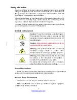
Page 12: ...12 http www tyan com NOTE ...

Page 13: ... 33 2 1 1 Removing the Chassis Cover 33 2 1 2 Replacing the Chassis Cover 34 2 1 3 Installing the CPU and Heatsink 35 2 1 4 Installing the Memory 38 2 1 5 Installing Hard Drives 39 2 1 6 Installing the Add On Card 41 2 1 7 Installing the M 2 Card 42 2 2 Rack Mounting 43 2 2 1 Installing the Server in a Rack 43 2 2 2 Installing the inner Rails to the Chassis 43 2 2 3 Installing the Outer Rails to t...

Page 14: ...ng the Motherboard 92 Chapter 5 Motherboard Information 95 5 1 Board Image 96 5 2 Block Diagram S8021 97 5 3 Motherboard Mechanical Drawing 98 5 4 Board Parts Jumpers and Connectors 99 5 5 Thermal Interface Material 106 5 6 Tips on Installing Motherboard in Chassis 107 5 7 Installing the Memory 109 5 8 Finishing Up 111 Chapter 6 BIOS Setup 113 6 1 About the BIOS 113 6 1 1 Setup Basics 113 6 1 2 Ge...

Page 15: ... Common Options Submenu 155 6 5 3 UMC Common Options Submenu 156 6 5 4 NBIO Common Options Submenu 158 6 5 5 FCH Common Options Submenu 160 6 6 Server Management 163 6 6 1 System Event Log 165 6 6 2 BMC Network Configuration 166 6 7 Security 167 6 8 Boot 168 6 8 1 Delete Boot Option 170 6 9 Save Exit 171 Chapter 7 Diagnostics 173 7 1 Flash Utility 173 7 2 AMIBIOS Post Code Aptio 174 Appendix I How...

Page 16: ...http www tyan com 16 NOTE ...

Page 17: ... high bandwidth memory design and lightning fast PCI E bus implementation The GA88 B8021 not only empowers your company in nowadays IT demand but also offers a smooth path for future application usage TYAN also offers the GA88 B8021 in a version that can support 2 hot swappable 2 5 SAS 12G SATA 6G HDDs SSDs The GA88 B8021 uses TYAN s latest chassis featuring a robust structure and a solid mechanic...

Page 18: ...pport SAS 12Gb s SATA 6Gb s Supported HDD Interface 2 SAS 12Gb s SATA 6Gb s System Cooling Configuration Redundancy Yes FAN 10 4cm fans Heat Sink 1 Passive CPU Heat sink Power Supply Type ERP1U Input Range AC 100 127V 12A AC 200 240V 9 48A Frequency 47 63 Hz Output Watts 1600 Watts Efficiency 80 plus Platinum Redundancy 1 1 NOTE 1 When use 100V 127V AC input the system does not support redundant P...

Page 19: ...e install TYAN Riser Card 1 M2091 R riser card right for 1 PCI E Gen3 x16 slot 1 M8021 R16 1L 1 riser card for 1 PCI E Gen3 x16 slot 2 M5631 R16 1F 1 riser card for 2 PCI E Gen3 x16 slots 1 M8021 R32 2L 2 riser card for 1 PCI E Gen3 x16 slot Others Field Upgradable Option Optional Riser Cards 1 M2091 R riser card right for 1 PCI E Gen3 x16 slot 1 M8021 R32 2L 1 riser card for 2 PCI E Gen3 x16 slot...

Page 20: ...supply LED Over temperature warning indicator Fan PSU fail LED indicator Others Watchdog timer support Server Management Onboard Chipset Onboard Aspeed AST2500 AST2500 iKVM Feature 24 bit high quality video compression Supports storage over IP and remote platform flash USB 2 0 virtual hub AST2500 IPMI Feature IPMI 2 0 compliant baseboard management controller BMC 10 100 1000 Mb s MAC interface BIO...

Page 21: ...40 C 70 C 40 F 158 F In Non operating Humidity 90 non condensing at 35 C RoHS RoHS 6 6 Compliant Yes Package Contains Barebone 1 GA88 B8021 Barebone Manual 1 Quick Installation Guide Installation CD 1 TYAN Device Driver CD NOTE 1 The specifications are subject to change without prior notice 2 Please visit our Web site for the latest specifications ...

Page 22: ...600W power supply unit 1 M1716G75 FPB 1 S8021 system board 10 System fans 4 PCI E Risers 1 M8021 R16 1L 1 1 M8021 R32 2L 2 2 M5631 R16 1F 1 1 M1287G88 BP12 2 HDD BP 1 M2091 R Riser card 3 Power Cable 500mm 1 Power Cable 150mm GA88 B8021 Accessories 2 AC Power code US 2 AC Power code EU 3 GPU GTX REAR BKT 1 CPU Heatsink 3 Power cable 600mm 1 Power cable 200mm 1 Air duct 4P 1 Air duct 1P 1 Air duct ...

Page 23: ...ct from different views 1 5 1 System Front View No Description 1 HDD LED 2 Warning LED 3 LAN1 LED 4 LAN2 LED 5 ID Power Dual color Blue ID LED Green Power ON 6 Reset Button 7 ID UID Button 8 Power On Off Button 9 USB3 0 Port 1 10 USB3 0 Port 2 11 2 5 HDD Bays 12 Fan Area Thermal Holes ...

Page 24: ...System Warning Amber Solid On System Warning Amber HDD HDD Ready Green HDD Access Green Blinking HDD Ready Green Off HDD Access Off LAN1 Access Green Access Green Blinking Linking Green Solid On Off Link Off Link Green Off Link Off LAN2 Access Green Access Green Blinking Linking Green Solid On Off Link Green Off Link Green Off Link Off Buttons Descriptions Reset Button Press to reset the system ID...

Page 25: ...tions Drive State Active LED Green Status LED Orange Drive present no activity Solid On Off Drive present with activity Blinking Off Drive Failed Don t care Solid On Drive dentify Don t care Blinking 1 Hz Drive Rebuild Don t care Blinking 4 Hz ...

Page 26: ...6 1 5 4 System Rear View No Description 1 Thermal Holes 2 PCIE x16 Gen 3 Slot via M2091 R FH HL 3 USB3 0 Port 4 LAN3 Realtek RTL8211E for dedicated IPMI 5 LAN2 Intel X550 AT2 6 LAN1 Intel X550 AT2 7 VGA Port 8 PSU1 9 PSU0 ...

Page 27: ...Green Blinking Yellow Solid On 10 Gbps Link Yellow Solid On Yellow Solid On Active Yellow Blinking Yellow Solid On 1Gbps LAN Port 1Gbps LAN Link Activity LED Scheme Left LED Link Activity LED Color Green Right LED Speed LED Color Amber No Link OFF OFF 10 Mbps Link Green Solid On OFF Active Green Blinking OFF 100 Mbps Link Green Solid On Green Solid On Active Green Blinking Green Solid On 1000 Mbps...

Page 28: ... where the power supply continues to operate high temp inlet temperature 54deg PMBus reading or hot spot temperature 105deg PMBus reading high power high current slow fan 1200rpm OFF 0 5Hz Blinking Amber AC present only 12VSB on PS off or PS in Smart Redundant state 0 5Hz Blinking Green OFF Output ON and OK ON OFF AC cord unplugged OFF ON FW update mode 2Hz Blinking Green OFF Warning All PSUs have...

Page 29: ...10 16 M5631 R16 1F 1 Riser Card FH FL DW PCI E Gen 3 x16 slot 6 SYS_FAN_11 12 17 M8021 R32 2L 2 Riser Card 7 SYS_FAN_13 14 18 M8021 R16 1L 1 Riser Card 8 SYS_FAN_15 16 19 Linkbar 9 SYS_FAN_17 18 20 PSU0 10 SYS_FAN_19 20 21 PSU1 11 M1287G88 BP12 2 HDD BP pre installed 22 PCIE Riser Card Bracket pre installed with M2091 R NOTE The system is pre installed with S8021 motherboard ...

Page 30: ...http www tyan com 30 NOTE ...

Page 31: ...accidentally damaging the internal components 2 0 3 Tools The following procedures require only a few tools including the following A cross head Phillips screwdriver A grounding strap or an anti static pad A T20 Security Torx screwdriver A Hex screwdriver Most of the electrical and mechanical connections can be disconnected using your fingers It is recommended that you do not use needle nosed plie...

Page 32: ... metal chassis of the unit case or the bare metal body of any other grounded appliance Avoid touching motherboard components IC chips connectors memory modules and leads The motherboard is pre installed in the system When removing the motherboard always place it on a grounded anti static surface until you are ready to reinstall it Hold electronic circuit boards by the edges only Do not touch the c...

Page 33: ...ncluding CPUs memory modules and Add on cards etc 2 1 1 Removing the Chassis Cover Follow these instructions to remove the GA88 B8021 chassis cover 1 Loosen the top screws on the chassis cover 2 Loosen the thumb screw on the back side of the chassis in a counterclockwise direction 2 Slide to take out the top cover from the chassis ...

Page 34: ...ons to replace the GA88 B8021 top chassis cover 1 Place the top cover onto the chassis and slide the top cover into place 2 Tighten the thumbscrew NOTE The thumbscrew should be tightened with a screwdriver after the top chassis are closed 3 Secure the top cover with three screws ...

Page 35: ...Torx screwdriver to loosen the screws securing the force frame in a sequential order 3 2 1 NOTE The force frame will automatically eject after the captive screws are being released 2 By placing your both index fingers on the sides on the metal handle pull to release the rail frame Then lift the rail frame to its fully open position ...

Page 36: ...erve the followings a make sure to push the carrier frame with package towards the end of the rail frame until it clicks into place b do not drop the carrier frame or touch the package pad to avoid component damage 4 Align and install the carrier frame with package into the slot on the rail frame ...

Page 37: ... of the rail frame firmly until it locks in place 6 Close the force frame Then use a T20 Torx screwdriver to tighten the screws to secure the force frame in a sequential order 1 2 3 7 Place the heatsink on top of the processor socket Screw the heatsink in a diagonal sequence to secure it to the chassis ...

Page 38: ...modules onto the motherboard 1 Press the memory slot locking levers in the direction of the arrows as shown in the following illustration 2 Align the memory module with the slot When inserted properly the memory slot locking levers lock automatically onto the indentations at the ends of the module ...

Page 39: ...rd Drives The GA88 B8021 supports two 2 5 Hard Drives Follow these instructions to install a hard drive 1 Press the locking lever to release the 2 5 SSD HDD tray 2 Pull out the 2 5 SSD HDD tray 3 Remove the 4 screws to detach HDD tray bracket ...

Page 40: ...http www tyan com 40 4 Place a hard drive into the drive tray Use four screws to secure the HDD 5 Reinsert the HDD tray into the chassis 6 Press the locking lever to lock the SSD HDD tray ...

Page 41: ...vailable with riser card The following instructions are for Add On card installation You may refer to the procedures below for the installation 1 Remove the screw of PCI E bracket and lift up the bracket 2 Remove the screw to slide the PCIE bracket 3 Insert the Add On card to the M2091 R riser card 4 Reinstall the M2091 R riser card to the chassis and secure with one screw ...

Page 42: ...Card Follow these instructions to install the M 2 Card 1 Take out the space supporter from the Accessory Box 2 Insert the space supporter into the mainboard and turn 900 3 Insert the M 2 card into the M 2 connector and push it down to lock in place ...

Page 43: ...mounting kit 2 2 1 Installing the Server in a Rack Follow these instructions to mount the TYAN GA88 B8021 into an industry standard 19 rack NOTE Before mounting the TYAN GA88 B8021 in a rack ensure that all internal components have been installed and that the unit has been fully tested However to make the installation easier we suggest that you remove all HDD trays before you insert the chassis in...

Page 44: ...http www tyan com 44 3 Pull the inner sliding rail forward to secure it to the chassis ...

Page 45: ...2 3 Installing the Outer Rails to the Rack 1 Secure the outer rails to the rack 2 2 4 Rack mounting the Server 1 Lift the unit and then insert the inner slide rails into the middle rails 2 Push the whole system into the rack ...

Page 46: ...http www tyan com 46 NOTE ...

Page 47: ...ackets in the chassis A power cable is normally required for each GPU card except for NVIDIA Tesla P4 In this chapter we will show how to install different types of GPU cards NOTE 1 Please contact your local dealer to purchases the accessory kit FRU SM 0040 before installing the GPU cards 2 Please visit our Web site http www tyan com for the latest GPU card support list 3 1 Installing the Front GP...

Page 48: ...http www tyan com 48 2 Unplug the power cable and lift up the Front GPU1 Bracket ...

Page 49: ...http www tyan com 49 3 Loosen four screws to remove the dummy bracket from the GPU card 4 After detaching the dummy bracket screw Screw 4 back onto the GPU card ...

Page 50: ... GPU screws and M3_L4 screws in the screw pack from the accessory box 6 Reinsert the Front GPU1 Bracket into the chassis and connect the Front GPU1 power cable to the motherboard Use three screws to secure the Front GPU1 Bracket to the chassis 7 Repeat the procedures described earlier to install the Front GPU2 and GPU3 Brackets ...

Page 51: ...http www tyan com 51 3 2 Installing the Rear GPU Card P100 1 Loosen 5 screws to lift up the Linkbar 2 Unscrew to lift up the Rear GPU4 Bracket ...

Page 52: ...http www tyan com 52 3 Unscrew to remove the dummy brackets 4 Insert the Nvidia P100 GPU card onto the Rear GPU4 Bracket 5 Secure the GPU card onto the GPU mounting bracket with 4 screws ...

Page 53: ... 53 6 Connect the Rear GPU4 power cable and re insert the Rear GPU4 Bracket into the chassis 7 Screw the Rear GPU4 Bracket to the chassis Follow the procedures described earlier to replace the Linkbar Cable Routing P100 ...

Page 54: ...Disconnect the power cable and then unscrew to lift up the Front GPU1 Bracket 2 Cut off the nylon cable tie to draw out the power cable 3 Unscrew to take off the mounting bracket 4 Take out the GTX rear bracket from the Accessory Box and screw it to the Front GPU1 Bracket ...

Page 55: ...4 from the Accessory Box and secure it to the Bracket with a nylon cable tie 6 Loosen five screws to remove the dummy bracket from the GTX GPU card After detaching the dummy bracket screw Screw 5 back onto the GPU card 7 Insert the GTX GPU card into the Front GPU1 Bracket ...

Page 56: ...e Bracket with 6 screws Use the original GPU screws and M3_L4 screws from the Accessory Box 9 Connect the GPU power cable to the GPU card 10 Reinsert and screw the Front GPU1 Bracket into the chassis Connect the GTX GPU power cable to the motherboard ...

Page 57: ...http www tyan com 57 3 4 Installing the Rear GPU Card GTX 1 Loosen 5 screws to lift up the Linkbar 2 Unscrew to lift up the Rear GPU4 Bracket ...

Page 58: ...acket and screw it to the Bracket 5 Take out the GTX GPU power cable PN 422T64100001 from the Accessory Box and connect to the GPU Card 6 Secure the Rear GPU4 Bracket to the chassis with 2 screws and connect the power cable to the motherboard Follow the procedures described earlier to replace the Linkbar ...

Page 59: ...http www tyan com 59 Cable Routing GTX ...

Page 60: ...t the power cable and then unscrew to lift up the Front GPU1 Bracket 2 Cut off the nylon cable tie to draw out the power cable 3 Unscrew to take off the mounting bracket Take out the MI25 rear bracket and screw it to the Front GPU3 Bracket 4 Unscrew to replace with the MI25 bracket ...

Page 61: ...com 61 5 Take out the MI25 GPU power cable and secure it to the Bracket with a nylon cable tie 6 Loosen screws to remove the dummy bracket from the MI25 GPU card 7 Insert the MI25 GPU card into the Front GPU1 Bracket ...

Page 62: ... Bracket with 4 screws Use the original GPU screws and M3_L4 screws from the Accessory Box 9 Connect the GPU power cable to the GPU card 10 Reinsert and screw the Front GPU1 Bracket into the chassis Connect the MI25 GPU power cable to the motherboard ...

Page 63: ...http www tyan com 63 3 6 Installing the Rear GPU Card MI25 1 Loosen 5 screws to lift up the Linkbar 2 Unscrew to lift up the Rear GPU4 Bracket ...

Page 64: ...3 Unscrew to remove the dummy brackets 4 Unscrew to replace with the MI25 Bracket 5 Insert the GPU card into the Rear GPU4 Bracket and screw it to the Bracket 6 Take out the MI25 GPU power cable and connect to the GPU Card ...

Page 65: ... www tyan com 65 7 Secure the Rear GPU4 Bracket to the chassis with 2 screws and connect the power cable to the motherboard Follow the procedures described earlier to replace the Linkbar Cable Routing MI25 ...

Page 66: ...ble and then unscrew to lift up the Front GPU1 Bracket 2 Cut off the nylon cable tie and draw out the power cable from the Front GPU1 Bracket 3 Unscrew the Front GPU1 Bracket to remove the original mounting bracket Take out the optional P4 mounting bracket and screw it to the Front GPU1 Bracket ...

Page 67: ... tyan com 67 4 Unscrew to remove the dummy bracket 5 Insert the P4 GPU card into the Front GPU1 Bracket and secure the GPU card with 2 screws 6 optional for Front GPU1 2 Brackets only Take out the GPU Air Duct ...

Page 68: ...ins and install the GPU Air Duct to Front GPU1 as shown 8 optional for Front GPU1 2 Bracket only Screw the GPU Air Duct and Front GPU1 Bracket to the chassis 9 optional for Front GPU2 Bracket only Insert the P4 Air Duct Wall into the chassis Align the P4 Air Duct Wall with the guide pins as shown below ...

Page 69: ... optional for Front GPU2 Bracket 2 only Screw the P4 Air Duct and Front GPU2 Bracket into the chassis 11 Unscrew to lift up the Front GPU3 Bracket 12 Insert the cards into the Front GPU3 Bracket and screw them to the Bracket ...

Page 70: ...http www tyan com 70 13 Repeat the procedures described earlier in reverse order to re install the Front GPU3 Bracket ...

Page 71: ...http www tyan com 71 3 7 Installing the Rear GPU Card P4 1 Loosen 5 screws to lift up the Linkbar 2 Unscrew to lift up the Rear GPU4 Bracket ...

Page 72: ...ew to remove the mylar and M8021 R16 1L 1 Riser Card Take out the M8021 R32 2L 1 for replacement 5 Screw the new riser card M8021 R32 2L 1 and mylar to the Rear GPU4 Bracket 6 Insert the Nvidia P4 GPU cards into the Rear GPU4 Bracket and screw the cards to the Bracket ...

Page 73: ... Re insert and screw the Rear GPU4 Bracket to the chassis and remove the Rear GPU4 power cable Follow the procedures described earlier to replace the Linkbar Cable Routing P4 NOTE No power cable connection is required for P4 ...

Page 74: ...r Duct The GA88 B8021 system chassis air ducts are equipped in the accessory kit Follow the instruction below to install all four air ducts onto the chassis 1 Align the air duct with the guide pins and then install the air duct onto the chassis ...

Page 75: ...http www tyan com 75 2 The air duct installation is now completed ...

Page 76: ...http www tyan com 76 NOTE ...

Page 77: ...o replace the pre installed components including the S8021 Motherboard M1716G75 FPB Front Panel Board M1287G88 BP12 2 HDD BP Board M8021 R16 1L 1 M5631 R32 2L 2 M5631 R16 1F 1 M2091 R Riser Card System Fan and Power Supply etc 4 2 Disassembly Flowchart The following flowchart outlines the disassembly procedure ...

Page 78: ...d The GA88 B8021 has preinstalled 2 M5631 R16 1F 1 1 M8021 R16 1L 1 1 M8021 R32 2L 2 and 1 M2091 R riser cards NOTE The pre installed riser cards are listed below 1 M5631 R16 1F 1 2 M8021 R32 2L 2 3 M8021 R16 1L 1 4 M2091 R The following instructions show you how to detach the PCIE riser card and the riser bracket 1 Remove the 3 screws to release the mylar and M5631 R16 1F 1 riser card ...

Page 79: ...e mylar and M8021 R32 2L 2 riser card 3 Remove the 4 screws to release the mylar and M8021 R16 1L 1 riser card 4 Remove the 2 screws to release the M2091 R riser card 5 Follow the procedures described earlier in reverse order to replace with a new riser card ...

Page 80: ... 6mm thickness 1 6mm Layer 6 layers I O Port 1 PCIE x16 slot M8021 R16 1L M8021 R16 1L Riser Card PCB Dimensions 200 37 1 6mm thickness 1 6mm Layer 6 layers I O Port 1 PCIE x16 slot M8021 R16 1L 1 M8021 R16 1L 1 Riser Card PCB Dimensions 228 45 39 42 1 6mm thickness 1 6mm Layer 8 layers I O Port 1 PCIE x16 slot ...

Page 81: ...ckness 1 6mm Layer 8 layers I O Port 2 PCIE x16 slots M8021 R32 2L 2 M8021 R32 2L 2 Riser Card PCB Dimensions 276 45 39 1 6mm thickness 1 6mm Layer 8 layers I O Port 2 PCIE x16 slots M2091 R M2091 R Riser Card PCB Dimensions 127 88 59 62 1 6mm thickness 1 6mm Layer 4 layers I O Port 1 PCIE x16 slots ...

Page 82: ...eplacing the HDD Backplane Follow these instructions to replace the M1287G88 BP12 2 HDD Backplane Board 1 Disconnect all the cables connected to the HDD Backplane 2 Remove the two screws securing the bracket to the chassis base ...

Page 83: ... 1 HDD Backplane Features Front View Rear View M1287G88 BP12 2 HDD BP Board PCB Dimensions 93 36 2mm Layer 4 layers Integrated I O 2 SATA Connectors 1 JTAG Jumper J1 1 SGPIO Connector J2 2 HDD connector 1 4 Pin Power connector ...

Page 84: ..._5_RUN P8 P9 VDD_5_RUN HD0_PRS_L P10 P11 SAS0_LED GND P12 P13 HD0_V12HD VDD_5_RUN P14 P15 VDD_5_RUN GND S1 GND1 GND GND GND2 HDD1 HDD Connector Definition Pin Pin Definition SAS_TX1 S2 S3 SAS_TX1 GND S4 S5 SAS_RXBN1 SAS_RXBP1 S6 S7 GND SAS0_PRESENT_L S8 S9 NC NC S10 S11 GND NC S12 S13 NC GND S14 P1 NC NC P2 P3 NC GND P4 P5 GND GND P6 P7 HD1_V5 VDD_5_RUN P8 P9 VDD_5_RUN HD1_PRS_L P10 P11 SAS1_LED G...

Page 85: ... SAS_RXBP1 GND 7 J1 JTAG Connector Definition Pin Pin Definition CPLD_JTAG_TCK 1 2 GND CPLD_JTAG_TDO 3 4 VDD_3P3_RUN CPLD_JTAG_TMS 5 6 NC NC 7 8 NC CPLD_JTAG_TDI 9 10 GND J2 SGPIO Connector Definition Pin Pin Definition SMBUS_3V3_CLK 1 2 SAS_SIO_DIN_A SMBUS_3V3_DATA 3 4 SAS_SIO_DOUT_A GND 5 6 SAS_SIO_END_A NC 7 8 SAS_SIO_CLK_A VCC3_AUX 9 10 NC PW1 Power Connector Definition Pin Pin Definition VDD_...

Page 86: ...http www tyan com 86 4 6 Replacing the System Fan Follow these instructions to replace the system fan 1 Disconnect the fan cable 2 Lift up the fan to replace with a new one ...

Page 87: ...nt Panel Board 1 Disconnect both cables from the front panel board 2 Unscrew the front panel board module 3 Unscrew the front panel board from the front panel tray for a new one 4 Prepare a new one to replace Follow the procedure described earlier in reverse order to reinsert the front panel board into the chassis ...

Page 88: ...t Panel Board Features Front View Rear View Form Factor 28 x 35 4 x 1 6 mm 4 layer PCB Specifications I O 2 USB3 0 Port LED Indicators 1 HDD LED 1 Warning LED 2 LAN LED 1 Power ID LED Switch 1 Reset Button 1 ID Button 1 Power Button ...

Page 89: ...er Button J4 Front Panel Control Board Connector J7 USB3 0 Connector J4 FPIO Connector Definition Pin Pin Definition PW_LED 1 2 VCC_FPB NC 3 4 ID_LED PW_LED 5 6 ID_LED HD_LED 7 8 BMC_HW_FAULT_N HD_LED 9 10 BMC_SYS_FAULT_N FP_PWR_BTN_N 11 12 LAN1_LED GND 13 14 LAN1_LED FP_RST_BTN_N 15 16 NC GND 17 18 NC FP_IDLED_BTN_N 19 20 NC TEMP_SENSOR 21 22 LAN2_LED HD_FAIL_LED 23 24 LAN2_LED NC 25 26 NC NC 27 ...

Page 90: ...CC_FPB 1 2 USB3_N5_RX_FPB USB3_P5_RX_FPB 3 4 GND USB3_N5_TX_FPB 5 6 USB3_P5_TX_FPB GND 7 8 USB2_N4_FPB_R USB2_P4_FPB_R 9 10 USB3_FPB_OC_N_R USB2_P6_FPB_R 11 12 USB2_N6_FPB_R GND 13 14 USB3_P6_TX_FPB USB3_N6_TX_FPB 15 16 GND USB3_P6_RX_FPB 17 18 USB3_N6_RX_FPB USB3_VCC_FPB 19 ...

Page 91: ...replace the power supply follow these instructions 1 Press the tab as shown in the diagram and pull out the power 2 Free the power from the power socket 3 Replace a new single power and reinsert it into the power socket following the above steps in reverse ...

Page 92: ...http www tyan com 92 4 9 Replacing the Motherboard Follow these instructions to remove all of below mentioned cables on the motherboard from the chassis 1 Disconnect all cables on the motherboard ...

Page 93: ...http www tyan com 93 2 Loosen five screws to lift up the Linkbar 3 Unscrew to lift up the PCIE Riser Card Bracket ...

Page 94: ... modules from the chassis 5 Unscrew to lift up all GPU Card Brackets Refer to Chapter 3 for instruction on how to remove GPU Card Brackets 6 Unscrew all mounting screws on the board and carefully remove the board Make sure not to scrape on chassis stand offs ...

Page 95: ...est conditions MITAC recommends wearing a static safety wrist strap 2 Hold the motherboard by its edges and do not touch the bottom of the board or flex the board in any way 3 Avoid touching the motherboard components IC chips connectors memory modules and leads 4 Place the motherboard on a grounded antistatic surface or on the antistatic bag that the board was shipped in 5 Inspect the board for d...

Page 96: ...ttp www tyan com 96 5 1 Board Image S8021 This picture is representative of the latest board revision available at the time of publishing The board you receive may not look exactly like the above picture ...

Page 97: ...http www tyan com 97 5 2 Block Diagram S8021 ...

Page 98: ...http www tyan com 98 5 3 Motherboard Mechanical Drawing ...

Page 99: ...sion available at the time of publishing The board you receive may not look exactly like the above diagram The DIMM slot numbers shown above can be used as a reference when reviewing the DIMM population guidelines shown later in the manual For the latest board revision please visit our web site at http www tyan com ...

Page 100: ...U Power Connector PE_PW2 10 SATA Header SATA0 30 Front Panel Pin Header FPIO_2 11 Clear CMOS J194 31 USB3 0 Front Header USB_FPIO_1 12 CPU FAN Connector CPU0_FAN_1 32 M 2 Connector M2_1 13 PCIE Routing Switch 3PHD11 33 M 2 Connector M2_2 14 GPU Power Connector PE_PW1 34 SATA DOM Header SATADOM1 15 System FAN Connector SYS_FAN_5 6 35 SATA DOM Header SATADOM2 16 System FAN Connector SYS_FAN_7 8 36 T...

Page 101: ...IE 3 GPU3 J112 B Power Supply Slot PSU1 G PCIE 5 GPU5 J113 C Power Supply Slot PSU0 H PCIE 6 GPU6 J197 D PCIE 1 GPU1 J115 I PCIE 4 GPU4 J198 E PCIE 2 GPU2 J114 Jumper Legend OPEN Jumper OFF Without jumper cover CLOSED Jumper ON With jumper cover ...

Page 102: ...to connect the cooling fan to your motherboard to keep the system stable and reliable SYS_FAN_1 20 8 pin System Fan Connector Signal Pin Pin Signal GND1 1 5 GND2 P12V1 2 6 P12V2 FAN_TACH1 3 7 FAN_TACH2 FAN_PWM1 4 8 FAN_PWM2 J116 small 4 pin Power Connector Signal Pin Pin Signal P12V_IN 1 3 GND GND 2 4 VCC5 SATADOM1 SATADOM2 SATA DOM Header Signal Pin Pin Signal GND 1 6 sSATA6G_RX_P4 sSATA6G_TX_P4 ...

Page 103: ...PP_EN FPIO_2 Front Panel Connector Signal Pin Pin Signal FP_PW_LED_PW 1 2 FP_PWER VCC3_AUX KEY 3 4 FP_ID_LED_PW FP_PW_LED_GND 5 6 FP_ID_LED_N HDD_LED_PW 7 8 BMC_HW_FAULT_N HDD_ACT_LED_N 9 10 BMC_SYS_FAULT_N FP_PWR_BTN_N 11 12 LAN0_LED_P GND 13 14 LAN0_LED_N FP_RST_BTN_JP_N 15 16 FP_SMB_DAT GND 17 18 FP_SMB_CLK FP_IDLED_BTN_N 19 20 FP_INTRUSION_N SYS_Air_Inlet 21 22 LAN1_LED_P FP_NMI_BTN_N 23 24 LA...

Page 104: ...OAD KEY 7 8 SCLOCK VDD_33_DUAL 9 10 NI SATA0 SATA1 SATA Connector 7 1 1 GND Connects to the Serial ATA ready drives via the Serial ATA cable 2 SSATA_TX 3 SSATA_TX 4 GND 5 SSATA_RX 6 SSATA_RX 7 GND 3PHD11 PCIE Routing Switch Jumper Signal Pin Pin Signal PULL UP 1 2 GPU_SELECT_L GND 3 Pin1 2 closed G0 GPU1 P1 SLOT7 Pin2 3 closed P1 GPU1 G0 SLOT7 Default J2 Console Switch Jumper Signal Pin Pin Signal...

Page 105: ...eed to clear the system BIOS setting 1 Power off system and disconnect power connectors from the motherboard 2 Remove the jumper cap from Pin_1 and Pin_2 Default setting 3 Move the jumper cap to close Pin_2 and Pin_3 for several seconds to Clear CMOS 4 Put jumper cap back to Pin_1 and Pin_2 Default setting 5 Reconnect power connectors to the motherboard and power on system Clear CMOS ...

Page 106: ...to touch this material Simply remove the protective cover and place the heat sink on the processor The second type of interface material is usually packaged separately It is commonly referred to as thermal compound Simply apply a thin layer on to the CPU lid applying too much will actually reduce the cooling NOTE Always check with the manufacturer of the heat sink processor to ensure that the ther...

Page 107: ...re install the support studs If you are unsure of stud placement simply lay the motherboard inside the chassis and align the screw holes of the motherboard to the studs inside the case If there are any studs missing you will know right away since the motherboard will not be able to be securely installed NOTE Be especially careful to look for extra stand offs If there are any stand offs present tha...

Page 108: ...age to your motherboard Some chassis include plastic studs instead of metal Although the plastic studs are usable MITAC recommends using metal studs with screws that will fasten the motherboard more securely in place Below is a chart detailing what the most common motherboard studs look like and how they should be installed ...

Page 109: ...of the type of memory recommended for your motherboard This platform supports 8 8 DDR4 slots Up to 2 048GB RDIMM 1 024GB LRDIMM 2 048GB LRDIMM 3DS are supported All installed memory will automatically be detected No jumpers or settings need to be changed for memory detection All memory must be of the same type and density Different memory types can NOT be mixed and matched on the same motherboard ...

Page 110: ...2_UMC1_CH_G1 P0_D2_UMC0_CH_H0 P0_D2_UMC0_CH_H1 NOTE 1 indicates a populated DIMM slot 2 Use paired memory installation for max performance 3 Populate the same DIMM type in each channel specifically Use the same DIMM size Use the same of ranks per DIMM 4 Every DIMM Channel 1 is master 0 is slave 5 AMD Naples includes 4 dies every dies support individual PCIE device Detail as below GPU1 GPU2 DIMM A1...

Page 111: ...properly especially SATA cables and most importantly jumpers You may have difficulty powering on your system if the motherboard jumpers are not set correctly In the rare circumstance that you have experienced difficulty you can find help by asking your vendor for assistance If they are not available for assistance please find setup information and documentation online at our website or by calling ...

Page 112: ...http www tyan com 112 NOTE ...

Page 113: ...s and configurations of the BIOS are current at the time of print and are subject to change and therefore may not match exactly what is displayed on screen This section describes the BIOS setup program The setup program lets you modify basic configuration settings The settings are then stored in a dedicated battery backed memory called NVRAM that retains the information even when the power is turn...

Page 114: ...for best performance and reliability Even a seemingly small change to the Chipset setup options may cause the system to become unstable or unusable 6 1 4 Setup Variations Not all systems have the same BIOS setup layout or options While the basic look and function of the BIOS setup remains more or less the same for most systems the appearance of your Setup screen may differ from the charts shown in...

Page 115: ...that can directly be changed within the Main Setup screen BIOS Information It displays BIOS related information Memory Information This displays the total memory size System Date Set the Date Use Tab to switch between Date elements Default Ranges Year 2010 2079 Months 1 12 Days dependent on month System Time Set the Time Use Tab to switch between Time elements ...

Page 116: ...ation parameters Onboard Device Configuration Onboard Device and Function Configuration PCIE Slot Configuraion Onboard PCIE Slot Configuration Trusted Computing Trusted Computing settings ACPI Settings System ACPI Parameters Hardware Health Configuration Hardware Health Configuration AST2500 Super IO Configuration System Super IO Chip Parameters ...

Page 117: ...ort Console Redirection PCI Subsystem Settings PCI PCI X and PCI Express Settings Network Stack Configuration Network Stack Settings CSM Configuration CSM Configuration Enable Disable Option ROM execution setting etc SATA Configuration SATA Device Information USB Configuration USB Configuration Parameters ...

Page 118: ... com 118 6 3 1 CPU Configuration SVM Mode Enable disable CPU Virtulization Disabled Enabled SMEE Control secure memory encryption enable Disabled Enabled Node 0 Information View Memory Information related to Node 0 ...

Page 119: ...http www tyan com 119 6 3 1 1 Node0 Information Read only ...

Page 120: ...ard External Onboard VGA Enable Disable ASPEED VGA Disabled Enabled Onboard LAN X550 Enable Disable Onboard LAN Devices Disabled Enabled LAN1 OPROM Enable Disable Load Option ROM For Onboard LAN Disabled Enabled with iSCSI Enabled with PXE LAN2 OPROM Enable Disable Load Option ROM For Onboard LAN Disabled Enabled with PXE ...

Page 121: ...http www tyan com 121 Serial IRQ Mode Configure Serial IRQ Mode Quiet Continuous ...

Page 122: ...nabled Disabled PCIE Slot2 GPU2 Enable Disable Load option ROM for PCIE Slot2 GPU2 Enabled Disabled PCIE Slot3 GPU3 Enable Disable Load option ROM for PCIE Slot3 GPU3 Enabled Disabled PCIE Slot4 GPU4 Enable Disable Load option ROM for PCIE Slot4 GPU4 Enabled Disabled PCIE Slot5 GPU5 Enable Disable Load option ROM for PCIE Slot5 GPU5 Enabled Disabled ...

Page 123: ...or PCIE Slot2 GPU2 Auto Gen 1 2 5 GT s Gen 2 5 GT s Gen 3 8 GT s PCIE Slot3 GPU3 Maximum Link Speed for PCIE Slot3 GPU3 Auto Gen 1 2 5 GT s Gen 2 5 GT s Gen 3 8 GT s PCIE Slot4 GPU4 Maximum Link Speed for PCIE Slot4 GPU4 Auto Gen 1 2 5 GT s Gen 2 5 GT s Gen 3 8 GT s PCIE Slot5 GPU5 Maximum Link Speed for PCIE Slot5 GPU5 Auto Gen 1 2 5 GT s Gen 2 5 GT s Gen 3 8 GT s PCIE Slot6 Maximum Link Speed fo...

Page 124: ...sted Computing Security Device Support Enable or disable BIOS support for security device O S will not show Security device O S will not show Security Device TCG EFI protocol and INT1A interface will not be available Enabled Disabled ...

Page 125: ...http www tyan com 125 6 3 5 ACPI Settings Enable ACPI Auto Configuration Enable or disable BIOS ACPI Auto Configuration Disabled Enabled ...

Page 126: ... Hardware Health Configuration Auto Fan Control Auto Fan Control help Automatic Manual Full Speed BMC Alert Beep Enable Disable BMC Alert Beep On Off PMBus support PMBus Support Enabled Disabled Number of PSU Number of PSU 1 1 1 ...

Page 127: ...m 127 6 3 6 1 Sensor Data Register Monitoring When you enter the Sensor Data Register Monitoring submenu you will see the following dialog window pop out Please wait 8 10 seconds NOTE SDR can not be modified Read only ...

Page 128: ...http www tyan com 128 6 3 7 AST2500 Super IO Configuration Super IO Chip Read only ...

Page 129: ... disable Serial Port COM Enabled Disabled Device Settings Read only Change Settings Select an optimal setting for Super IO Device Auto IO 3F8h IRQ 4 IO 3F8h IRQ 3 4 5 6 7 9 10 11 12 IO 2F8h IRQ 3 4 5 6 7 9 10 11 12 IO 3E8h IRQ 3 4 5 6 7 9 10 11 12 IO 2E8h IRQ 3 4 5 6 7 9 10 11 12 ...

Page 130: ...ed Select Dynamic Time system will wake on the current time increase minute s Disabled Fixed Time Dynamic Time When Wake system from S5 is set to Fixed Time Wake up hour Select 0 23 For example enter 3 for 3am and 15 for 3pm Wake up minute Select 0 59 for Minute Wake up second Select 0 59 for Second When Wake system from S5 is set to Dynamic Time Wake up Minute increase 1 5 ...

Page 131: ...ces EMS Console Redirection Console redirection enable or disable Disabled Enabled Legacy Console Redirection Settings Legacy Console redirection settings Console Redirection Settings The settings specify how the host computer which the user is using will exchange data Both computers should have the same or compatible settings ...

Page 132: ...cond Select serial port transmission speed The speed must be matched on the other side Long or noisy lines may require lower speeds 38400 9600 19200 115200 57600 Data Bits 8 7 Parity A parity bit can be sent with the data bits to detect some transmission errors Even parity bit is 0 if the num of 1 s in the data bits is even Odd parity bit is 0 if the num of 1 s in the data bits is odd Mark parity ...

Page 133: ...al can be sent to stop the data flow Once the buffers are empty a start signal can be sent to re start the flow Hardware flow control uses two wires to send start stop signal None Hardware RTS CTS VT UTF8 Combo Key Support Enable VT UTF8 Combination Key Support for ANSI VT100 terminals Enabled Disabled Recorder Mode With this mode enabled only text will be sent This is to capture Terminal data Dis...

Page 134: ...solution On Legacy OS the Number of Rows and Columns supported redirection 80x24 80x25 Redirect After POST when Bootloader is selected then Legacy Console Redirection is disabled before booting to legacy OS when Always Enable is selected then Legacy Console Redirection is enabled for Legacy OS Default setting for this option is set to Always Enable Always Enable BootLoader ...

Page 135: ...erver OS through a serial port COM0 Terminal Type VT UTF8 is the preferred terminal type for out of band management The next best choice is VT100 and then VT100 See above in Console Redirection Settings page for more Help with Terminal Type Emulation VT UTF8 VT100 VT100 ANSI Bits per Second Select serial port transmission speed The speed must be matched on the other side Long or noisy lines may re...

Page 136: ...hen sending data if the receiving buffers are full a stop signal can be sent to stop the data flow Once the buffers are empty a start signal can be sent to restart the flow Hardware flow control uses two wires to send start stop signal None Hardware RTS CTS Data Bits Parity Stop Bits Read only ...

Page 137: ...es to be decoded in Above 4G Address Space Only if System supports 64 bit PCI Decoding Enabled Disabled SR IOV Support If system has SR IOV capable PCIe devices this option Enable or Disable Single root IO virtualization Support Enabled Disabled PCI Express Settings Change PCI Express Devices Settings ...

Page 138: ...http www tyan com 138 6 3 10 1 PCI Express Subsystem Maximum Payload Set Maximum Payload of PCI Express Device or allow System BIOS to select the value Auto 128 Bytes 256 Bytes ...

Page 139: ... When Network Stack is set to Enabled Ipv4 PXE Support Enable IPV4 PXE Boot Support If disabled IPV4 PXE boot option will not be created Disabled Enabled Ipv4 HTTP Support Enable IPV4 HTTP Boot Support If disabled IPV4 HTTP boot option will not be created Disabled Enabled Ipv6 PXE Support Enable IPV6 PXE Boot Support If disabled IPV6 PXE boot option will not be created Disabled Enabled ...

Page 140: ...Enable IPV6 HTTP Boot Support If disabled IPV6 HTTP boot option will not be created Disabled Enabled PXE boot wait time Wait time to press ESC key to abort the PXE boot 0 Media detect count Number of times presence of media will be checked 1 ...

Page 141: ...ssages Set display mode for Option ROM Force BIOS Keep Current Network Controls the execution of UEFI and Legacy PXE OpROM Do not launch UEFI Legacy Storage Controls the execution of UEFI and Legacy PXE OpROM Do not launch UEFI Legacy Video Controls the execution of UEFI and Legacy PXE OpROM Do not launch UEFI Legacy ...

Page 142: ...http www tyan com 142 Other PCI devices Determines OpRom execution policy for devices other than network storage or video Do not launch UEFI Legacy ...

Page 143: ...http www tyan com 143 6 3 13 SATA Configuration Read only ...

Page 144: ...ble only for EFI applications Enabled Disabled Auto XHCI Hand off This is a workaround for OSes without XHCI hand off support The XHCI ownership change should be claimed by XHCI driver Enabled Disabled USB Mass Storage Driver Support Enable Disable USB Mass Storage Driver Support Disabled Enabled USB transfer time out The time out value for Control Bulk and Interrupt transfers 20 sec 10 sec 5 sec ...

Page 145: ...t command time out 20 sec 10 sec 30 sec 40 sec Device power up delay Maximum time the device will take before it properly reports itself to the Host Controller AUTO uses default value for a Root port it is 100 ms for a Hub port the delay is taken from Hub descriptor Auto Manual ...

Page 146: ... Mode Simultaneous multithreading OFF 1T single thread Auto 2T two thread if capable Off Auto Numa Enable or Disable Non uniform Memory Access NUMA Disabled Enabled North Bridge North Bridge Parameters Error Management Error Management settings ...

Page 147: ...http www tyan com 147 6 4 1 North Bridge Configuration Memory Configuration Memory Configuration Socket 0 Configuration View Information related to Socket 0 ...

Page 148: ...http www tyan com 148 6 4 1 1 Memory Configuration Memory Clock This option allows User to select different memory Clock Default value is 800 Mhz Auto 1333MHz 1600MHz 1866MHz 2133MHz 2400MHz 2666MHz ...

Page 149: ...http www tyan com 149 6 4 1 2 Socket 0 Information Read only ...

Page 150: ...http www tyan com 150 6 4 2 Error Management Platform First Error Handling Enable Disable PFEH Disabled Enabled MCA Error Threshold Count MCA Error Threshold Count 0 Disable Error 0 1 5 10 100 1000 ...

Page 151: ... com 151 6 5 AMD CBS Menu Zen Common Options Zen Common Options DF Common Options DF Common Options UMC Common Options UMC Common Options NBIO Common Options NBIO Common Options FCH Common Options FCH Common Options ...

Page 152: ... Controls IO based C state generation and DF C states Disabled Enabled Auto SEV ES ASID Space Limit SEV VMS using ASIDs below the SEV ES ASID Space Limit must enable the SEV ES feature The valid values for this field are from 0x1 1 0x10 16 1 Core Thread Enablement Core Thread Enablement Prefetcher Settings Prefetcher Settings ...

Page 153: ...lement Submenu Downcore control Sets the number of cores to be used Once this option has been used to remove any cores a POWER CYCLE is required in order for future selections to take effect TWO 1 1 TWO 2 0 THREE 3 0 FOUR 2 2 FOUR 4 0 SIX 3 3 Auto ...

Page 154: ... 5 1 2 Prefetcher Settings Submenu L1 Stream HW Prefetcher Option to Enable Disable L1 Stream HW Prefetcher Enabled Disabled Auto L2 Stream HW Prefetcher Option to Enable Disable L2 Stream HW Prefetcher Enabled Disabled Auto ...

Page 155: ...nterleaving Controls fabric level memory interleaving AUTO none channel die socket Note that channel die and socket has requirements on memory populations and it will be ignored if the memory doesn t support the selected option None Channel Die Socket Auto Memory interleaving size Controls the memory interleaving size The valid value are AUTO 256 bytes 512 bytes 1 Kbytes or 2Kbytes This determines...

Page 156: ...http www tyan com 156 6 5 3 UMC Common Options Submenu DRAM Memory Mapping DRAM Memory Mapping ...

Page 157: ...www tyan com 157 6 5 3 1 DRAM Memory Mapping Submenu Chipselect Interleaving Interleave memory blocks across the DRAM chip selects for node 0 Disabled Auto BankGroupSwap No help string Enabled Disabled Auto ...

Page 158: ...r Auto Use default performance determinism settings power performance Auto Power Perfomance cTDP Control Auto Use the fused cTDP Manual User can set customized cTDP Manual Auto ACS Enable No help string Enable Disabled Auto PCIe ARI Support Enables Alternative Routing ID Interpretation Disabled Enabled Auto ...

Page 159: ...http www tyan com 159 6 5 4 1 NB Configuration Submenu IOMMU Enable Disable IOMMU Disabled Enabled Auto ...

Page 160: ...http www tyan com 160 6 5 5 FCH Common Options Submenu AC Power Loss Options AC Power Loss Options UART Configuration Options UART Configuration Options ...

Page 161: ...http www tyan com 161 6 5 5 1 AC Power Loss Options Submenu Restore AC Power Loss Select Restore AC Power Loss Method Power Off Power On Last State ...

Page 162: ... UART 0 has no HW FC if UART 2 is enabled Disabled Enabled Auto UART 0 Legacy Options No help string Disabled 0x2E8 0x3F8 0x3E8 0x3F8 UART 1 Enable UART 1 has no HW FC if UART 3 is enabled Disabled Enabled Auto UART 1 Legacy Options No help string Disabled 0x2E8 0x3F8 0x3E8 0x3F8 ...

Page 163: ...ed 3 minutes 4 minutes 5 minutes 6 minutes FRB 2 Timer Policy Configure how the system should respond if the FRB 2 Timer expires Not available if FRB 2 Timer is disabled Do Nothing Reset Power Down Power Cycle OS Watchdog Timer If enabled starts a BIOS timer which can only be shut off by Management Software after the OS loads Helps determine that the OS successfully loaded or follows the OS Boot W...

Page 164: ... minutes OS Wtd Timer Policy Configure how the system should respond if the OS Boot Watchdog Timer expires Not available if OS Boot Watchdog timer is disabled Do Nothing Reset Power Down Power Cycle BMC Logo Enable or Disable BMC Logo Enabled Disabled System Event Log Press Enter to change the SEL event log configuration BMC network configuration Configure BMC network parameters ...

Page 165: ...ents is set to Disabled the following items are read only Erase SEL Choose options for erasing SEL No Yes on next reset Yes on every reset When SEL is Full Choose options for reactions to a full SEL Do Nothing Erase Immediately Log EFI Status Codes Disable the logging of EFI Status Codes or log only error code or only progress code or both Disabled Both Error Code Progress Code ...

Page 166: ...ied option will not modify any BMC network parameters during BIOS phase Unspecified Static DynamicBmcDhcp DynamicBmcNonDhcp Management Port 2 Enable Disable BMC Share NIC Disabled Enabled Configure IPV6 support Management Port 1 IPV6 Support Enable or Disable LAN1 IPV6 Support Disabled Enabled Management Port 2 IPV6 Support Enable or Disable LAN2 IPV6 Support Disabled Enabled ...

Page 167: ...he Confirm New Password window will pop out to ask for confirmation User Password Set user password in the Create New Password window After you key in the password the Confirm New Password window will pop out to ask for confirmation Secure Frozen Mode Disable means Hard Drive on Non frozen mode Enable means Hard Drive on Frozen mode Disabled Enabled ...

Page 168: ...conds to wait for setup activation key 65535 0xFFFF means indefinite waiting 1 Bootup NumLock State Select the keyboard NumLock state Off On Quiet Boot Enable or disable Quiet Boot option Disabled Enabled Endless Boot Enable or disable Endless Boot Disabled Enabled ...

Page 169: ...http www tyan com 169 Wait for ESC If Error Wait for ESC key to be pressed if error occurs Disabled Enabled Boot Option Priorities Boot Option 1 Select the first second boot device Device Name Disabled ...

Page 170: ...http www tyan com 170 6 8 1 Delete Boot Option Delete Boot Option Remove an EFI boot option from the boot order Select one to delete UEFI Built in EFI Shell ...

Page 171: ...g any changes Save Changes and Reset Reset the system after saving the changes Discard Changes and Reset Reset system setup without saving any changes Save Changes Save changes done so far to any of the setup options Discard Changes Discard changes done so far to any of the setup options Restore Defaults Restore Load Default values for all the setup options ...

Page 172: ...http www tyan com 172 Save as User Defaults Save the changes done so far as User Defaults Restore User Defaults Restore the User Defaults to all the setup options Boot Override Read only ...

Page 173: ... 7 1 Flash Utility Every BIOS file is unique for the motherboard it was designed for For Flash Utilities BIOS downloads and information on how to properly use the Flash Utility with your motherboard please check the TYAN web site at http www tyan com NOTE Please be aware that by flashing your BIOS you agree that in the event of a BIOS flash failure you must contact your dealer for a replacement BI...

Page 174: ... 0xD0 0xDF DXE errors 0xE0 0xE8 S3 Resume PEI 0xE9 0xEF S3 Resume errors PEI 0xF0 0xF8 Recovery PEI 0xF9 0xFF Recovery errors PEI Standard Checkpoints SEC Phase Status Code Description 0x00 Not used Progress Codes 0x01 Power on Reset type detection soft hard 0x02 AP initialization before microcode loading 0x03 North Bridge initialization before microcode loading 0x04 South Bridge initialization be...

Page 175: ...dge initialization is started 0x1A Pre Memory South Bridge initialization South Bridge module specific 0x1B Pre memory South Bridge initialization South Bridge module specific 0x1C Pre Memory South Bridge initialization South Bridge module specific 0x1D 0x2A OEM pre memory initialization codes 0x2B Memory initialization Serial Presence Detect SPD data reading 0x2C Memory initialization Memory pres...

Page 176: ...compatible memory speed 0x51 Memory initialization error SPD reading has failed 0x52 Memory initialization error Invalid memory size or memory modules do not match 0x53 Memory initialization error No usable memory detected 0x54 Unspecified memory initialization error 0x55 Memory not installed 0x56 Invalid CPU type or speed 0x57 CPU mismatch 0x58 CPU self test failed or possible CPU cache error 0x5...

Page 177: ...eps Description 1 repeatedly Memory not installed 1 Memory was installed twice InstallPEIMemory routine in PEI Core called twice 2 Recovery started 3 DXEIPL was not found 3 DXE Core Firmware Volume was not found 4 Recovery failed 4 S3 Resume failed 7 Reset PPI is not available DXE Phase Status Code Description 0x60 DXE Core is started 0x61 NVRAM initialization 0x62 Installation of the South Bridge...

Page 178: ...le specific 0x75 South Bridge DXE initialization South Bridge module specific 0x76 South Bridge DXE initialization South Bridge module specific 0x77 South Bridge DXE initialization South Bridge module specific 0x78 ACPI module initialization 0x79 CSM initialization 0x7A 0x7F Reserved for future AMI DXE codes 0x80 0x8F OEM DXE initialization codes 0x90 Boot Device Selection BDS phase is started 0x9...

Page 179: ...ization 0xB3 System Reset 0xB4 USB hot plug 0xB5 PCI bus hot plug 0xB6 Clean up of NVRAM 0xB7 Configuration Reset reset of NVRAM settings 0xB8 0xBF Reserved for future AMI codes 0xC0 0xCF OEM BDS initialization codes DXE Error Codes 0xD0 CPU initialization error 0xD1 North Bridge initialization error 0xD2 South Bridge initialization error 0xD3 Some of the Architectural Protocols are not available ...

Page 180: ... Checkpoints Status Code Description 0x01 System is entering S1 sleep state 0x02 System is entering S2 sleep state 0x03 System is entering S3 sleep state 0x04 System is entering S4 sleep state 0x05 System is entering S5 sleep state 0x10 System is waking up from the S1 sleep state 0x20 System is waking up from the S2 sleep state 0x30 System is waking up from the S3 sleep state 0x40 System is waking...

Page 181: ...ent shall Tyan be liable for direct indirect incidental special or consequential damages arising from the BIOS update or recovery The BIOS Recovery file is named xxxx cap where the xxxx portion is the motherboard model number Examples 5630 cap 7106 cap 7109 cap etc Please make sure that you are using the correct BIOS Recovery file from Tyan s web site BIOS Recovery Process 1 Place the recovery BIO...

Page 182: ...ot the server during the BIOS recovery process This can damage the BIOS recovery bootloader and prevent it from loading a subsequent time 7 Wait for the BIOS recovery procedure to complete Completion is signified with the message Flash update completed Press any key to reset the system displayed on screen 8 Remove the USB disk and reboot If your system does not have video output or the POST code h...

Page 183: ...an3 SYS_FAN_5 6 FAN3 Fan4 SYS_FAN_7 8 FAN4 Fan5 SYS_FAN_9 10 FAN5 Fan6 SYS_FAN_11 12 FAN6 Fan7 SYS_FAN_13 14 FAN7 Fan8 SYS_FAN_15 16 FAN8 Fan9 SYS_FAN_17 18 FAN9 Fan10 SYS_FAN_19 20 FAN10 2 SATA Cable S4P PWR Cable SGPIO Cable SATA SAS Backplane BP Board to S8021MB M1287G88 BP12 2 Connect to S8021 SATA Cable SATA0 SATA1 SATA0 SATA1 S4P PWR Cable PW1 J116 SGPIO Cable J2 SGPIO0 ...

Page 184: ...http www tyan com 184 3 FP Ctrl Cable USB Cable Front Panel Board FPB to S8021 MB M1716G75 FPB Connect to S8021 Control Cable J4 FPIO_2 USB 3 0 Cable J7 USB3_FPIO1 ...

Page 185: ...ard A table of BIOS Temp sensor name explanation is also included for readers reference Figure 1 Sensor Location NOTE The red spot indicates the sensor Fan and Temp Sensor Location 1 Fan Sensor It is located in the third pin of the fan connector which detects the fan speed rpm 2 Temp Sensor refer to Figure 1 Sensor Location They detect the system temperature around ...

Page 186: ...http www tyan com 186 BIOS Temp Sensor Name Explanation ...

Page 187: ...http www tyan com 187 ...

Page 188: ... Max Temperature of P0_D3_UMC0_CH_E Slot P0_D3_UMC1_CH_F The Max Temperature of P0_D3_UMC1_CH_F Slot P0_D2_UMC1_CH_G The Max Temperature of P0_D2_UMC1_CH_G Slot P0_D2_UMC0_CH_H The Max Temperature of P0_D2_UMC0_CH_H Slot GPU1_Core0_Temp Temperature of GPU1 Core0 GPU1_Core1_Temp Temperature of GPU1 Core1 GPU2_Core0_Temp Temperature of GPU2 Core0 GPU2_Core1_Temp Temperature of GPU2 Core1 GPU3_Core0_...

Page 189: ...S_FAN_12 SYS_FAN_13 Fan speed of SYS_FAN_13 SYS_FAN_14 Fan speed of SYS_FAN_14 SYS_FAN_15 Fan speed of SYS_FAN_15 SYS_FAN_16 Fan speed of SYS_FAN_16 SYS_FAN_17 Fan speed of SYS_FAN_17 SYS_FAN_18 Fan speed of SYS_FAN_18 SYS_FAN_19 Fan speed of SYS_FAN_19 SYS_FAN_20 Fan speed of SYS_FAN_20 PSU0_Status Current PSU0 Status PSU1_Status Current PSU1 Status ...

Page 190: ...http www tyan com 190 NOTE ...

Page 191: ...BU 30 AWG 650 mm SATA CABLE SAS WIRE SATA 7P 2 SATA 7P 2 R A GA88 B5631 FRU CS 0460 332810000515 TF POWER CORD SBU EU 250 V 16 AWG 1 0mm 1800mm AC PWR CORD FRU CS 0550 332810000517 TF POWER CORD SBU US 250 V 16 AWG 1 31mm 1800mm AC GTX GPU FRU SM 0041 342T56700009 TF GPU GTX REAR BKT SBU SGCC GA88 B5631 422T56700004 TF AC DC POWER CABLE SBU 20 AWG 600MM GPU PWR 422T54100001 TF AC DC POWER CABLE SB...

Page 192: ...AR BKT SBU SGCC NCT GA88 B8021 FRU SO 0180 346T58100008 TF AIR DUCT P4 WALL MYLAR SBU MYLAR L282 5 W62 T0 76MM PC1870 BLACK GA88 B8021 FRU SO 0190 346T58100009 TF AIR DUCT P4 GPU MYLAR SBU MYLAR L125 W58 T0 43MM PC1870 BLACK GA88 B8021 MI25 Mode 2 FRU SO 9230 422T58100002 TF AC DC POWER CABLE SBU 20 AWG 200mm GPU PWR CABLE 2 4P M P4 2 2 3P 2 1P M 2pcs P4 2 GA88 B8021 422T59000003 TF AC DC POWER CA...

Page 193: ...r expectations TYAN s website http www tyan com provides easy to access resources such as in depth Linux Online Support sections with downloadable Linux drivers and comprehensive compatibility reports for chassis memory and much more With all these convenient resources just a few keystrokes away users can easily find their latest software and operating system components to keep their systems runni...

Page 194: ...proper maintenance of products NOTE A receipt or copy of your invoice marked with the date of purchase is required before any warranty service can be rendered You may obtain service by calling the manufacturer for a Return Merchandise Authorization RMA number The RMA number should be prominently displayed on the outside of the shipping carton and the package should be mailed prepaid TYAN will pay ...

Reviews: