


FIST-MB2-S
I N S T A L L A T I O N I N S T R U C T I O N
FIST Medium Box for Cable Splicing Only
1 Introduction
1.1 Product description
2 General
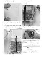
2.1 Tools
2.2 Kit contents
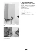
3 Installation and pre
assembling of box
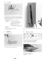
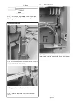
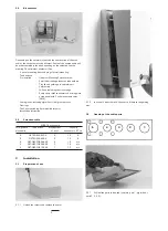
3.1 Preparation of box
3.2 Opening of the ports
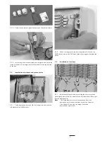
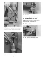
3.3 Installation of wrap around groove
plates
3.4 installation of the splicing trays
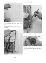
3.5 Mounting of the box on the wall
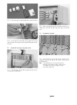
4 Cable installation
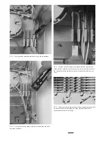
4.1 Cable preparation
4.2 Cable termination
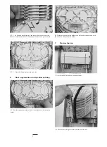
5. Fiber routing to individual trays
5.1 Allocation of the loose tubes in the tube holder
5.2 Routing of the cable fibers
6 Fiber organisation after splicing
7 Closing the box
8 Important steps
9 Rearrangements
Contents
1 Introduction
1.1 Product Description
The FIST-MB2-S is a Generic Box for a fiber management system that offers the function of splicing cables to
cables. It provides a mechanical and environmental protection for all the fiber optic components and permits
easy access by both the network provider and the customer. The box is applicable indoor and inside street
cabinets.
The FIST-MB2-S box is designed to splice fibers and can handle 96 splices (fully occupied by SE-trays).
2 General
2.1 Tools
Hammer
Screwdriver
Marker
Fiber guiding pin
FACC-tube-cutter-01
to cut loose tubes
FIST-GB-CUT-TOOL-PG16
to cut holes for glands
FACC-TUBE-Stripper-02
to strip loose tubes
FACC-HEAT-GUN-220V or 110V 1460W hot air gun
to install the heatshrink cable seals


