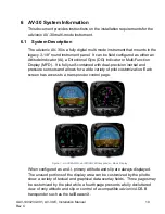
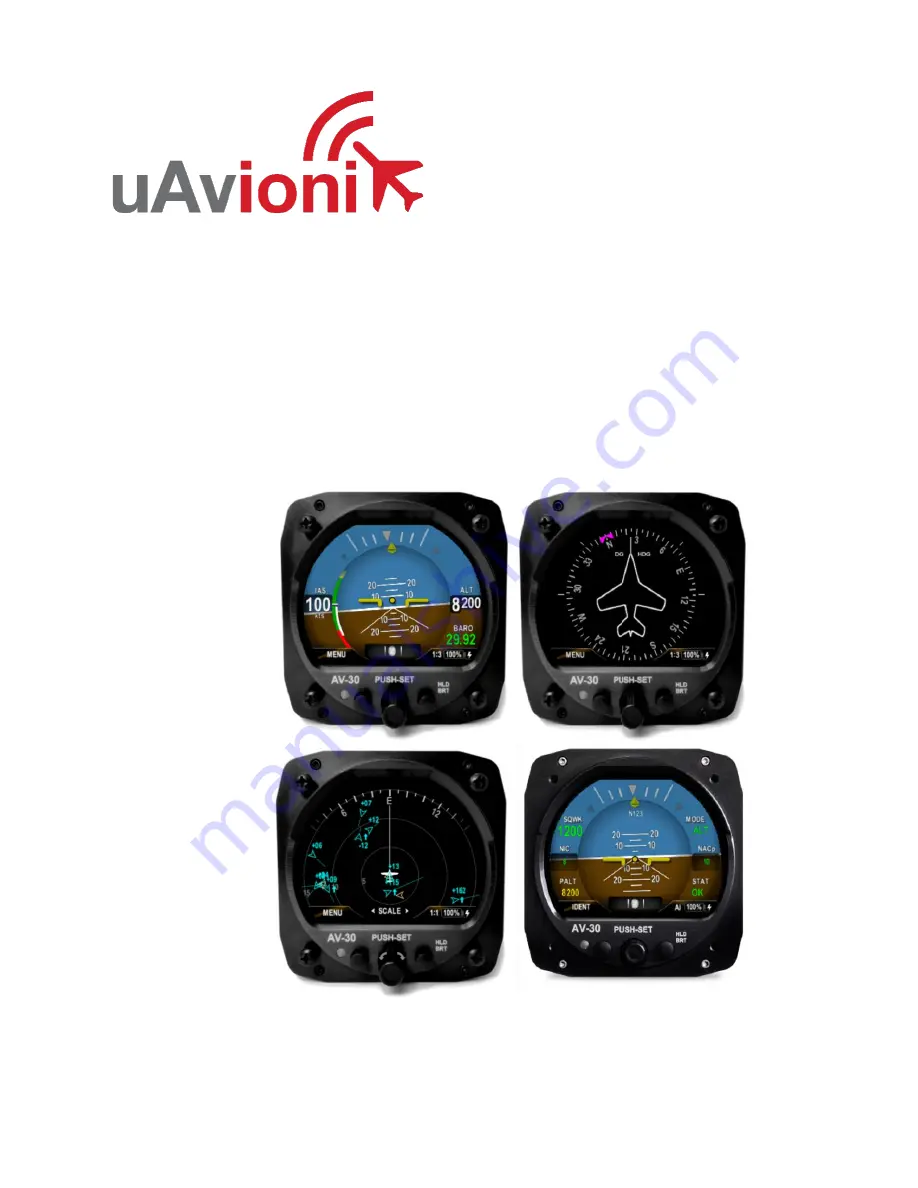
background image

UAV-1004234-001 
Rev C 


AV-30-E  

Installation Manual


Summary of Contents for AV-30-E

Page 1: ...UAV 1004234 001 Rev C AV 30 E Installation Manual ...

Page 2: ...permissions to download a single copy of this guide onto an electronic storage medium to be viewed for personal use provided that the complete text of this copyright notice is retained Unauthorized commercial distribution of this manual or any revision hereto is strictly prohibited uAvionix and Ping are registered trademarks of uAvionix Corporation and may not be used without express permission of...

Page 3: ...ate Comments A 6 2 2020 Initial release B 1 12 2021 Software update 1 1 0 C 7 22 2021 Software update 2 1 1 Added Transponder control Added AV Link installation Added definition of acronyms terms section Added magnetometer aiding and calibration Added requirement of pitot and static ...

Page 4: ...sification Number ECCN 7A994 These items are controlled by the U S Government and authorized for export only to the country of ultimate destination for use by the ultimate consignee or end user s herein identified They may not be resold transferred or otherwise disposed of to any other country or to any person other than the authorized ultimate consignee or end user s either in their original form...

Page 5: ...odified or altered Disclaimer of Warranty IN NO EVENT SHALL UAVIONIX BE LIABLE FOR ANY INCIDENTAL SPECIAL INDIRECT OR CONSEQUENTIAL DAMAGES WHETHER RESULTING FROM THE USE MISUSE OR INABILITY TO USE THE PRODUCT OR FROM DEFECTS IN THE PRODUCT SOME STATES DO NOT ALLOW THE EXCLUSION OF INCIDENTAL OR CONSEQUENTIAL DAMAGES SO THE ABOVE LIMITATIONS MAY NOT APPLY TO YOU Warranty Service Warranty repair se...

Page 6: ...Installation Locations 16 8 2 Operating Mode Configuration 16 9 Functionality and Required Interfaces 17 9 1 Aircraft Systems Connections 17 9 2 Feature Matrix 18 9 2 1Power Input Required 19 9 2 2Pitot and Static Interfaces Required 19 9 2 3Outside Air Temp Input Optional 19 9 2 4Audio Output Optional 20 9 2 5GPS Interface Optional 20 9 2 6Transponder Control Optional 21 9 2 7AV Link Interface Op...

Page 7: ...rom Instrument Panel Optional 32 11 1 9 AV 30 Backshell Connector Removal 33 11 1 10 AV Link Attachment 33 11 1 11 AV 30 Reinstallation in Instrument Panel 35 11 1 12 Continued Airworthiness 35 11 1 13 System Limitations 35 11 1 14 Connecting to the AV Link Web Browser 35 11 1 15 Wi Fi Firmware Update Page 36 11 2 Transponder tailBeaconX 37 11 2 1 Transponder Control 37 11 2 2 Transponder Testing ...

Page 8: ... 13 1 8 Demo Mode 45 13 2 System Checkout 46 13 2 1 Alignment 46 13 2 2 Gyro Calibration 47 13 2 3 Mag Calibration Flight 49 13 2 4 OAT Interface 50 13 2 5 GPS Navigator Interface 50 14 Troubleshooting 52 15 Serial Interface Specification 53 16 Field Update Capability 54 ...

Page 9: ...cal Standard Order VMC Minimum controllable airspeed VYSE Best rate of climb speed with one engine inoperative V2 Take off safety speed The lowest speed at which the aircraft complies with the handling criteria associated with the climb VT Threshold crossing speed target speed after V2 has been reached VSO Minimum stall speed with gear and full flaps The bottom end of the ASI white arc VS1 Minimum...

Page 10: ...FD It is fully self contained with dual precision inertial and pressure sensors and allows for a wide variety of pilot customization Each screen has access to a transponder control page Figure 1 AV 30 Multi Mode AI DG MFD Transponder Basic Display When configured as an AI primary attitude and slip are always displayed The unused portions of the display area can be customized by the pilot to show a...

Page 11: ...hen configured to allow Multi Function Display MFD functionality ADS B In traffic information can be displayed In all operating modes the pilot may select from multiple visual styles which are intended to improve visual compatibility with legacy aircraft instrumentation and preserve the look and feel of older aircraft applications A wide variety of supplemental functions including audio alerting d...

Page 12: ... Airspeed Altitude V Speeds Angle of Attack Vertical Trend Vertical Speed Set Altitude Heading Bus Voltage G Load Outside Air Temp True Airspeed Density Altitude GPS Navigator Waypoint Data GPS Navigator Nav Data GPS Navigator Route Line Heading Bug MFD traffic page with AV Link Transponder control Audio and Visual Alerting Functions AoA Alerting G Limit Alerting Excessive Roll Alerting Misc Funct...

Page 13: ... 8 Round Instrument Hole Dimensions w o Connector 3 38 x 3 38 x 1 6 Inches Weight 0 56 Lbs Electrical Connector 15 Pin Male D Sub Pneumatic Connectors 1 4 OD Quick Connect Mounting 4X 6 32 Machine Screws Case Material Billet Aluminum Environmental Ground Survival Low 55 C Operating Low 20 C Ground Survival High 85 C Operating High 55 C Altitude 25 000 Feet maximum Optical Characteristics Diagonal ...

Page 14: ...e installer must ensure that all installation limitations as defined in this document are observed The internal battery capacity has been tested and verified to provide 30 minutes of operational capacity with reserve and meets the requirements defined in CFR 23 1311 a 5 and 23 1353 h allowing independent operation from the primary electrical power system For aircraft capable of acrobatic flight th...

Page 15: ...ure Actuated Sensitive Type Type I SAE AS8005A Minimum Performance Standard Temperature Instruments Class IIIc SAE AS8034 Minimum Performance Standard for Airborne Multipurpose Electronic Displays N A RTCA DO 334 Minimum Operational Performance Standards MOPS for Strapdown Attitude and Heading Reference Systems AHRS A5 H9 T7 ASTM F3011 13 Standard Specification for Performance of Angle of Attack S...

Page 16: ...s of installation locations as a non required instrument The existing mechanically based altimeter and airspeed indicator must remain in their factory locations for this installation configuration 8 2 Operating Mode Configuration The AV 30 operating mode is configured during installation and can be set as follows Unit locked as a dedicated Attitude Indicator AI Mode Unit locked as a dedicated Dire...

Page 17: ...aircraft systems connections are provided on the single 15 Pin D sub connector and two quick connect pneumatic fittings Various interfaces are optional as indicated in the following diagrams Do not plug the pitot and static lines Figure 3 AV 30 Aircraft Systems Interfaces AI Mode Figure 4 AV 30 Aircraft Systems Interfaces DG Mode ...

Page 18: ... Static Baro Altitude Textual Pitot Static Angle Of Attack Graphical Pitot Static Vertical Trend Graphical Pitot Static Vertical Speed Textual Pitot Static Set Altitude Textual None Heading Textual Pitot Static Bus Voltage Textual None G Load Textual None Outside Air Temp Textual OAT Probe True Airspeed Textual Pitot Static OAT Probe Density Altitude Textual Pitot Static OAT Probe GPS Navigation W...

Page 19: ...derived angle of attack AoA True Airspeed TAS Density Altitude DALT DG heading and traffic altitude all require pitot and static connections as they are based on either altitude or airspeed measured from those connections When installed as a DG the pitot and static connections must be connected for Outside Air Temperature OAT backup battery in flight and DG heading aid TAS and DALT are the only ai...

Page 20: ...o connect directly to an audio panel typically a non switched or unswitched audio input High power outputs capable of directly driving a cockpit speaker are not provided Other unswitched unmuted inputs can be used but they may need to be mixed with an existing audio source Audio shields must be grounded only at audio panel to avoid ground loops Contact audio manufacture for further instructions Wh...

Page 21: ...ction 15 Serial Interface Specification 9 2 6 Transponder Control Optional The AV 30 has the option of being the control interface for select uAvionix transponders including the BeaconX family This provides pressure altitude mode squawk code and IDENT information to the transponder and displays status and annunciations from the transponder See section 9 2 for more information on the installation o...

Page 22: ...s pressed after power has been removed the AV 30 will go to battery mode 3 If the AV 30 senses airspeed it will stay in battery mode Make sure that the caps have been removed from the back of the AV 30 pitot and static ports If the AV 30 needs to be shut down after removing power push and hold the left and right buttons until the unit shuts down See the Pilots Guide UAV 1004233 001 10 Internal Bat...

Page 23: ...rform leak check after installation 10 2 Supplied Components Table 4 Supplied Components Component Part Number Description AV 30 E Unit UAV 1004035 001 AV 30 E Unit UAV 1004035 002 AV 30 E Unit with Internal Magnetometer AV 30 E Installation Kit UAV 1004091 001 Installation Kit 10 3 Non Supplied Components Table 5 Non Supplied Components Component Description Pitot Static Tubing Length as required...

Page 24: ...UAV 1004234 001 AV 30 E Installation Manual 24 Rev C 10 4 Mechanical Drawing Figure 5 Mechanical Drawing ...

Page 25: ...ternal components Installing a mounting screw that is longer than optimal will not damage the unit but will result in the unit not being fully fastened to the panel Mounting Screw Optional Spacing Washer Instrument Panel Internal Components Figure 6 Mounting Screw Dept Limits The installation kit contains multiple length screws to assist in compensating for different instrument panel thicknesses C...

Page 26: ... and therefore wiring varies based on installation Figure 7 and Figure 8 show connections for each configuration The primary difference is that the DG does not support audio alerting See AC 43 13 1B Chapter 11 7 for acceptable wire types for both power and interconnect purposes Figure 7 Wiring Diagram Attitude Indicator Position Installation ...

Page 27: ...G Position Installation 10 7 Bonding Requirements The following figure shows the grounding requirements for the electrical connections The two D Sub screws are to be utilized for shield and ground strap connections The supplied ring terminal connectors are sized for these screws ...

Page 28: ...p 8 or Less in Length The exposed non shielded portions of the interface cables AND the shield grounds are to remain less than 2 5 inches 2 5 Inches Maximum Non Shielded Shielded Figure 9 Shielded Cable The bond between the unit measured at the D sub screws to the aircraft frame must be 2 5 milli Ohms or less GROUND STRAP 8 AIRCRAFT GROUND CABLE SHIELD DRAIN 2 5 D SUB BACK SHELL Figure 10 Cable Sh...

Page 29: ...32 6 Spare Serial Input Reserved Do Not Connect 7 OAT Supply Output White Probe Wire 8 MFG Serial Input Reserved Do Not Connect 9 Ground Power Aircraft Ground 10 Aux Power Ret Power Reserved Do Not Connect 11 Audio H Output Audio Alerts hi 12 Audio L Output Audio Panel lo 13 Aux Power Out Power Reserved Do Not Connect 14 OAT Return Input White Blue Probe Wire 15 MFG Serial Output Reserved Do Not C...

Page 30: ...lent to an approved airframe specific maintenance manual installation design drawing or installation data package The content of this manual assumes use by competent and qualified personnel using standard maintenance procedures in accordance with Title 14 of the Code of Federal Regulation CFR and other related accepted procedures This is an incomplete system intended to provide the functions ident...

Page 31: ... Specifications Width 52 06 mm Height 25 91 mm Depth 52 63 mm Weight 1 1 oz 32 2 grams Operating temperature range 45 C to 70 C Maximum pressure altitude 35 000 ft Input voltage range 9 to 30 3 VDC 14V current 0 2A idle 0 25A typical 0 5A maximum 28V current 0 1A idle 0 125A typical 0 25A maximum Figure 12 AV Link connector size ...

Page 32: ...take advantage of AV Link the following equipment is required AV 30 3 1 8 Display 11 1 7 Mounting AV Link is mounted in series between the AV 30 and the AV 30 backshell connector 11 1 8 Removing AV 30 From Instrument Panel Optional It may be necessary because of space limitations to remove the AV 30 unit for performing AV Link installation Using a Phillips screwdriver remove the four 4 screws that...

Page 33: ...l the backshell connector is free to detach from the AV 30 If present leave the bonding ground strap attached to the backshell connector Figure 10 AV Link Backshell Connector Removal 11 1 10 AV Link Attachment Do not attempt to remove the two 2 captive Jack Screws from the AV Link housing Attach AV Link to the back of the AV 30 by inserting the unit into the DB 15 connector on the back of the AV 3...

Page 34: ... Jack Screws Do not attempt to use the Jack Screws to pull AV Link into the AV 30 connector AV Link should seat firmly into the AV 30 as shown in Figure 12 Figure 12 AV Link installed Using a 3 16 nut driver tighten the two 2 Jack Screws to 5 in lbs maximum Do Not Overtighten Reattach the original AV 30 Backshell Connector Using a flat screwdriver tighten the two 2 screws to 5 in lbs maximum Do No...

Page 35: ...itations for AV Link are determined by AV 30 limitations 11 1 14 Connecting to the AV Link Web Browser As shipped from the factory the AV Link will function in default mode and may not need customization If customization is required or firmware updates need applied then connect to the AV Link web browser with your personal computer Support for Windows MacOS iOS and other devices are supported usin...

Page 36: ... Page Note All settings changes should be performed while on the ground Accessing the AV Link web pages while in flight is not recommended and may disrupt normal operations of AV 30 and AV Link The AV Link firmware update page permits firmware updating of AV Link Click on Choose File Select the AV Link firmware update file to load and then click the OK button Click on Start Update to begin the fir...

Page 37: ...s designed to meet the transponder and ADS B requirements for operating in controlled airspace worldwide while minimizing installation costs 11 2 1 Transponder Control See AV 30 E Pilot s Guide UAV 1004233 001 for transponder control interface configuration 11 2 2 Transponder Testing with tailBeaconX Set AV 30 in STBY mode by following the above procedures Go to the tailBeaconX and connect to Wi F...

Page 38: ...mpany logo unit model number and the currently installed software version Figure 16 Splash Screen Operation in both AI and DG modes share common user interface controls as follows Rotary Knob with Momentary Push Left Push Button Right Push Button Hold For Brightness Adjust Photo Cell Auto Screen Brightness TFT Color Display Figure 17 Common User Interface Components ...

Page 39: ...233 001 AV 30 E Pilot s Guide and not addressed here The Setup Menu allows the pilot to set various configurations and alerting limits as desired for the type of operations being performed These are also covered in the Pilot s Guide referenced above The installer may wish to pre configure some or all these settings for the pilot but the default settings are acceptable The install menu is for setti...

Page 40: ...in control knob in while power is applied Figure 13 Installation Menu Access Keep the knob pressed until the startup logo has cleared The installation menu will now be enabled for access but will not automatically appear on the screen Ensure the unit is in AI or DG mode select the mode by pushing and holding the center button until the mode display changes When in AI or DG mode press and release t...

Page 41: ...ing the knob when the desired field is shown will allow the associated setting to be adjusted After adjustment pressing the knob again will exit the editing mode but the installation menu will remain active Figure 15 Exiting Edit Mode Pressing DONE or a lack of user input for 30 seconds will exit the installation menu and return to the primary screen Figure 16 Setup Done Exit Option ...

Page 42: ...ver exceed speed Set to match limits 40 to 300 knots 175 IAS VMC Minimum control airspeed with the critical engine inoperative Set to match limits 40 to 300 knots or disabled IAS VYSE Speed for best rate of climb OEI single engine Set to match limits 40 to 300 knots or disabled BARO UNITS Altimeter barometric units Inches of Mercury INHG Millibars MB TEMP UNITS OAT units Celsius C or Fahrenheit F ...

Page 43: ...vents the pilot from toggling the operating mode Installation on a non required instrument may be locked or not locked based on owner preferences Pressing and holding the center knob when functionality is not locked will toggle between AI DG and MFD modes 13 1 3 Trim Set Pitch Roll and Slip Trim to accommodate any mounting variations Set IAS and Altitude Trims to match existing instrumentation as ...

Page 44: ... format 9600 bps NMEA1 4800 NMEA format 4800 bps NMEA1 9600 NMEA format 9600 bps BEACON X tailBeaconX is installed SERIAL 2 If using the AV 30 as a control head for a tailBeaconX set SERIAL 2 to BeaconX otherwise select NONE Set to the corresponding input type Value Serial 2 Source NONE None available BEACON X tailBeaconX is installed APA MINI Future use SERIAL 3 If using the AV Link set SERIAL 3 ...

Page 45: ...correction data to DG and aiding to core AHRS algorithm Rotate the center knob until AID MODE is displayed If the internal magnetometer is available P N UAV 1004035 002 then you will have a choice of NONE MAG1 and MAG2 If the internal magnetometer is not found only NONE will be displayed Figure 17 AID Mode Selection Push the center knob and rotate to select your choice of Magnetometer aiding and t...

Page 46: ...ment do not move the aircraft This should extinguish within 3 minutes at which point valid attitude or direction indication is displayed If power is removed from the unit while it is still aligning the unit will go to battery mode until it has completed the alignment process Figure 18 Aligning Annunciator If the indicator is not extinguished within 3 minutes reference the troubleshooting section o...

Page 47: ...be completed on all units with software version 2 1 1 or later 2 With the AV 30 in the AI mode enter the Install menu page by pressing and releasing the left button repeatedly until the 3rd menu is displayed The aircraft must be on the ground with no movement Figure 19 Install Mode Selection 3 It is critical to ensure the aircraft is completely motionless and on the ground during the next several ...

Page 48: ...re 21 Gyro Calibration Procedure 6 AV 30 will indicate Calibration successfully completed Press DONE Push the left button under DONE and the calibration will be complete If an error is shown repeat the calibration process If any post accomplishment check fails please contact uAvionix support Figure 20 Gyro Calibration Selection ...

Page 49: ...f other flags Figure 22 Mag Calibration Flag and Selection 1 The Mag Cal is found in the install menu Hold down the center button while applying power The installation menu can now be accessed until the next power cycle 2 Once established in flight select MAG CAL Note that on units without an internal magnetometer MAG CAL will be disabled 3 Fly for 10 minutes Four 360 degree standard rate turns wi...

Page 50: ...ization guidance provided in the Pilots Guide to configure the display to show OAT in at least one textual display field Figure 24 OAT Indicator Note that OAT calibration is performed in the Setup procedures This step only ensures that the OAT probe is detected properly 13 2 5 GPS Navigator Interface If a GPS Navigator is connected utilize the display customization guidance provided in the Pilot s...

Page 51: ...Manual 51 Rev C Figure 25 GPS Data Elements On the GPS navigator set a destination waypoint and initiate a direct to sequence Note that not all navigators will output serial data until a waypoint has been selected and navigation initiated ...

Page 52: ... Battery Battery indication shows FAIL Contact uAvionix support Trim Roll Pitch or Slip show small but constant error Ensure unit is level in panel using a bubble level or similar Set trim adjustment in Installation menu See Installation Manual for instructions Airspeed or Altitude shows small but constant error Set trim adjustment in Installation menu See Installation Manual for instructions Inte...

Page 53: ...ets received are as follows Table 12 GPS Serial Specification Parameter Name Aviation Packet NMEA Packet GPS Track C Packet GPRMC Field 8 GPS Ground Speed D Packet GPRMC Field 7 Distance to Waypoint E Packet GPRMB Field 10 Cross Track Error G Packet GPRMB Field 2 Desired Track I Packet Computed Waypoint ID K Packet GPRMB Field 5 Bearing to Waypoint L Packet GPRMB Field 11 Magnetic Variation Q Pack...

Page 54: ... unit software can be field updated Updating requires either an in line harness and Windows based PC or the optional AV Link accessory to be installed Contact uAvionix support for additional information or reference available Service Bulletins Figure 26 Field Update Interface Diagram ...

Reviews: