background image

UAV-1003064-001

 Rev G 

Page 

1 | 50


m

icro

L

ink 

User and Installation  

                         Guide 


Summary of Contents for microLink

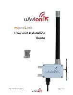
Page 1: ...UAV 1003064 001 Rev G Page 1 50 microLink User and Installation Guide ...

Page 2: ...y storage medium for any purpose without the express written permission of uAvionix uAvionix grants permissions to download a single copy of this guide onto an electronic storage medium to be viewed for personal use provided that the complete text of this copyright notice is retained Unauthorized commercial distribution of this manual or any revision hereto is strictly prohibited uAvionix and Ping...

Page 3: ...08 09 2019 Updated the skyStation statistics definitions and modified for uav files updating D 08 12 2019 Updated the FCC and IC statements per the TCB E 08 28 2019 Updated the RF exposure limits per the TCB F 12 18 2019 Added Updating instructions for skyStation and microLink radios G 7 21 2020 Updated configuration item descriptions Updated firmware upgrade instructions ...

Page 4: ... any transportation cost This warranty does not apply to cosmetic damage consumable parts damage caused by accident abuse misuse water fire or flood damage caused by unauthorized servicing or product that has been modified or altered IN NO EVENT SHALL UAVIONIX BE LIABLE FOR ANY INCIDENTAL SPECIAL INDIRECT OR CONSEQUENTIAL DAMAGES WHETHER RESULTING FROM THE USE MISUSE OR INABILITY TO USE THE PRODUC...

Page 5: ...adio System ARS 12 5 5 Typical System Configuration 12 5 6 Mechanical Specifications 14 6 Configuration 16 6 1 skyStation 16 6 2 Connection to the POE Network 17 6 3 skyStation Start up and Connection 18 6 3 1 Apply POE power to the skyStation 18 6 3 2 Run skyLinkApp exe 18 6 3 3 Connect to Mission Planner in TCP mode 20 6 3 4 skyLinkApp exe 22 6 3 5 Status Tab 23 6 3 6 Maps Tab 25 6 3 7 Configura...

Page 6: ...ev G Page 6 50 6 5 Updating Devices 39 6 5 1 Updating skyStation 39 6 5 2 Updating Ground microLink Radio 42 6 5 3 Updating Airborne microLink Radio 42 7 Appendix A Quick Start Guide 45 8 Appendix B HERE2 GPS Sharing 50 ...

Page 7: ...miniature Beyond Visual Line Of Sight BVLOS data link radio specifically designed for long range robust Unmanned Aircraft Systems UAS telemetry data links Ideal for size weight power and performance sensitive applications microLink operates in the 902 928MHz license free ISM band ...

Page 8: ...equency spreading Global Positioning System GPS Coordinated Universal Time UTC link synchronization Status integrity and health monitoring Environmental RTCA DO 160G Software RTCA DO 178C Level C Complex Hardware RTCA DO 254 Level C FCC 47 CFR Part 15 247 ID 2AFFTC2XISM Radio Specifications Band 902 928MHz ISM Band Architecture Dual Diversity Radios Transmit Power 1W 4W EIRP Spreading Code and Fre...

Page 9: ...terference received including interference that may cause undesired operation 5 2 2 Industry Canada Statement IC ID 25261 C2XISM In order to comply with FCC ISED RF Exposure requirements this device must be installed to provide at least 20 cm separation from the human body at all times Afin de se conformer aux exigences d exposition RF FCC ISED cet appareil doit être installé pour fournir au moins...

Page 10: ...applicables aux appareils radio exempts de licence L exploitation est autorisée aux deux conditions suivantes 1 l appareil ne doit pas produire de brouillage 2 l appareil doit accepter tout brouillage radioélectrique subi même si le brouillage est susceptible d en compromettre le fonctionnement ...

Page 11: ...ver Ethernet POE connectivity IP67 grade enclosure Dual Dipole Antennas Pole Mounting Kit Specification Value Input Power POE 13W Peak Size 122x82x60mm Weight 500 grams Operating Temp 45 to 70 C Interfaces User Protocol TCP or UDP Control Protocol TCP or UDP Timing Position Position Internal Environmental DO 160G Temperature Cat B2 ...

Page 12: ...V 5V 2 RXD IN Telem 3 TXD OUT Telem 4 RXD IN GPS 5 PPS IN 1PPS 6 GND Pin Type Physical Port 1 5V 5V 2 RXD IN GPS 3 UTC IN 1PPS 4 RXD IN Control 5 TXD OUT Control 6 GND 5 5 Typical System Configuration Transparent serial user data interface Plug and play with Ardupilot PixHawk autopilot Dual MMCX antenna connectors Supports NMEA UBX GPS Sensors such as HERE2 and truFYX ...

Page 13: ...V 1003057 001 microLink UAV 1002868 001 GPS Options truFYX kit UAV 1002500 001 HERE2 kit UAV 1002956 001 Replacement Parts skyLink Dipole Antenna UAV 1003060 001 MMCX 100mm UAV 1003063 001 MMCX 200mm UAV 1003063 002 GH 6p Cable UAV 1003061001 GH 8p Cable UAV 1003062 001 ...

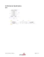
Page 14: ...UAV 1003064 001 Rev G Page 14 50 5 6 Mechanical Specifications ARS ...

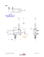
Page 15: ...UAV 1003064 001 Rev G Page 15 50 GRS ...

Page 16: ...UAV 1003064 001 Rev G Page 16 50 6 Configuration 6 1 skyStation Connect skyStation to a POE switch or POE power injector ...

Page 17: ...er 15 4W Voltage Range 37 57V Maximum Current 350mA Maximum Cable Resistance 20Ω Supported Cabling Shielded Cat 3 and Shielded Cat 5 Supported Modes Mode A endspan Mode B midspan Power Management Power Class 0 Maximum Cable Length 100 meters Caution Absolute maximum DC voltage 57 V A higher DC voltage value will permanently damage the equipment ...

Page 18: ...tening for incoming Control data on UDP port 30012 When the data arrives skyLinkApp exe will begin graphing the radio link statistics NOTE If you are not seeing the graphing as shown below it is likely your firewall is blocking the broadcast on port 30012 Please setup your firewall to allow skyLinkApp exe broadcast access to port 30012 skyLinkApp exe will populate the IP address of the skyStation ...

Page 19: ...UAV 1003064 001 Rev G Page 19 50 ...

Page 20: ...MissionPlanner http ardupilot org planner docs mission planner installation html Verify that the flight controller and skyStation are powered and running and that skyLinkApp exe is receiving data Run Mission Planner and select the communications drop down menu Select TCP as the communication mode and hit the Connect button on the upper right hand corner ...

Page 21: ...AV 1003064 001 Rev G Page 21 50 Enter the skyStation IP address as found earlier in skyLinkApp exe and click OK Enter port 30011 which is the skyStation default TCP port for Mission Planner and click OK ...

Page 22: ...ons 6 3 4 skyLinkApp exe skyLinkApp exe is the uAvionix Control channel monitoring application It is used or showing Status Maps and Configuration information It can be connected to the skyStation in TCP or UCP modes and the ports are configurable for network flexibility The mode and port selection must match the skyStation Configuration page setup and the IP address is always the IP address of th...

Page 23: ...adios It contains both transmit and receive information for the local and remote radios This information includes memory queue depth information transmit and receive data rates frame rates dropped frames and data totals It also shows the RSSI s on the primary and secondary radios for both the local and remote radios giving the user comprehensive information on the state of the system ...

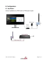
Page 24: ...UAV 1003064 001 Rev G Page 24 50 ...

Page 25: ...tistics detail shown below RSSI detail shown below 6 3 6 Maps Tab skyLinkApp exe has a mapping tab for mapping the local radio skyStation radio as well as the remote aircraft radio It includes latitude longitude altitude GPS fix type Slant Range and SV count ...

Page 26: ...064 001 Rev G Page 26 50 6 3 7 Configuration Tab skyLinkApp exe also contains a Configuration page This page is used for device settings and setup as well as system selecting the hop table scheme for the system ...

Page 27: ...UAV 1003064 001 Rev G Page 27 50 6 3 7 1 ARS Configuration Connect as shown below then run skyLinkApp ...

Page 28: ...e Configuration Tab Default to ISM Hopping Table Save Hop Table to Device o Station Type Airborne o UTC Pulse Polarity Positive o User Port Baud Rate 57600 o GPS Port Baud Rate 115200 o Control Port Baud Rate 115200 o Check Frame When Stale o Framer MTU 240 Save Device Configuration ...

Page 29: ...UAV 1003064 001 Rev G Page 29 50 6 3 7 2 GRS Configuration Connect as shown below then run the skyLinkApp ...

Page 30: ...e Configuration Tab Default to ISM Hopping Table Save Hop Table to Device o Station Type Ground o UTC Pulse Polarity Positive o User Port Baud Rate 57600 o GPS Port Baud Rate 115200 o Control Port Baud Rate 115200 o Check Frame When Stale o Framer MTU 240 Save Device Configuration ...

Page 31: ...ed devices or by using industry accepted network scanning tools Directions for each DHCP server router or network scanning tool differ Refer to the instruction manual for these devices or tools to help determine the IP address assigned to the skyStation The MAC address for each skyStation can be found on the device housing The following pages can be viewed in your web browser Note nnn nnn nnn nnn ...

Page 32: ...nn nnn nnn nnn api v1 stats Displays the status json sentence skyStation update URL http nnn nnn nnn nnn update Provides ability to update skyStation firmware The base URL displays configuration items as well as dynamic skyStation health statistics The defaults for the User and Control channel connections is shown All parameters can also be modified to fit your network needs ...

Page 33: ...UAV 1003064 001 Rev G Page 33 50 Figure 6 1 Default skyStation Settings ...

Page 34: ...ems Configuration Item Description User Connection Type These checkboxes indicate a connection type of UDP or TCP to the skyStation on the User connection The default User connection setting is TCP The User connection is typically a connection between the aircraft and the ground station software ...

Page 35: ...on will act as a TCP server and listen for incoming connections Alternatively if this address is a valid IP address the skyStation will act as a TCP client and will attempt to connect to a TCP server listening on User TCP IP Address User TCP Port 0 0 0 0 is the default setting for this parameter User TCP Port When the User Connection Type is TCP this is the port the TCP server listens on for incom...

Page 36: ...s address is a valid IP address the skyStation will act as a TCP client and will attempt to connect to a TCP server listening on Control TCP IP Address Control TCP Port 0 0 0 0 is the default setting for this parameter When using skyLinkApp this parameter must be set to 0 0 0 0 Control TCP Port When the Control Connection Type is TCP this is the port the TCP server listens on for incoming connecti...

Page 37: ...performs a system reset The screenshot above documents the factory default settings When you modify any configuration item press the Update button to store the changes These fields are non volatile and persist through power cycles 6 4 2 Health The Health section shows some real time statistics updated once every 2 seconds It will show if we are sending and receiving serial data and at what rates I...

Page 38: ...UAV 1003064 001 Rev G Page 38 50 Statistic Description User Serial Total KB Received This is the total number of bytes received on the User serial channel in kilobytes ...

Page 39: ...ckets received by the TCP IP stack TCP Transmit The number of TCP packets send by the stack TCP Drops The number of TCP packets dropped by the stack Free Space Memory free space Allocated Space Memory used space Version The version of software this skyStation running 6 5 Updating Devices The following sections outline the steps to update the firmware on the microLink radios and the skyStation Ther...

Page 40: ...owed by update Ex update Select Choose File and select the downloaded skyStation firmware Then click Upload DO NOT DISCONNECT THE SKYSTATION OR CLOSE THE WEBBROWSER UNTIL UPDATE IS COMPLETE Once file upload is complete click the button that says Reset MCU Once Reset is complete unplug the skyStation from the POE and plug it back in to finish the update Follow steps 1 3 to get reconnected the skySt...

Page 41: ...UAV 1003064 001 Rev G Page 41 50 Verify the device version has properly been updated ...

Page 42: ...the skyStation When the IP address is known open a web browser and in the URL search bar enter the IP address followed by radioupdate ex radioupdate Select Choose File and select the downloaded microLink firmware Then click Start Update DO NOT DISCONNECT THE SKYSTATION OR CLOSE THE WEBBROWSER UNTIL UPDATE IS COMPLETE When update is complete you will automatically be directed back to the main statu...

Page 43: ...ecent microLink firmware onto a Mac or PC Run the PingBootFlasher software and connect to the microLink radio by selecting the correct COM port on the Port dropdown then press connect When connected you will see the current App Version and PingBoot Status Idle on the PingBootFlasher software ...

Page 44: ...are Then click Flash DO NOT DISCONNECT THE MICROLINK RADIO OR CLOSE THE PING BOOT FLASHER UNTIL UPDATE IS COMPLETE When update is complete unplug the microLink radio and plug it back into the Mac or PC Reconnect the PingBootFlasher to the microLink radio and verify the App Version has updated ...

Page 45: ...radio to the Telemetry 1 port on your Pixhawk2 Connect the Control radio port which is the bottom port on the radio your truFYX GPS Power on your aircraft flight control system Launch the skyLinkApp exe application available at www uavionix com and use it to validate communications as well as retrieve the skyStation IP address the DHCP server gives the skyStation for connecting to Mission Planner ...

Page 46: ...UAV 1003064 001 Rev G Page 46 50 ...

Page 47: ...UAV 1003064 001 Rev G Page 47 50 Connect Mission Planner to the skyStation using a TCP connection to the skyStation IP Address and the default skyStation TCP port of 30011 ...

Page 48: ...UAV 1003064 001 Rev G Page 48 50 Use the IP address of the skyStation obtained from the skyLinkApp or from your list of DHCP connected devices Use the skyStation default port of 30011 ...

Page 49: ...UAV 1003064 001 Rev G Page 49 50 Once connected and all the parameters are downloaded you are ready to plan your mission and fly ...

Page 50: ...UAV 1003064 001 Rev G Page 50 50 8 Appendix B HERE2 GPS Sharing HERE2 GPS Sharing shown below ...

Reviews: