background image


SERVICE MANUAL 


UCHIDA YOKO CO., LTD., TOKYO, JAPAN 


V1.00 


Summary of Contents for AeroCut X

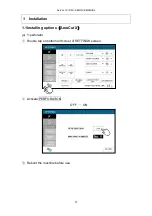
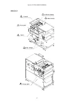
Page 1: ...SERVICE MANUAL UCHIDA YOKO CO LTD TOKYO JAPAN V1 00 ...

Page 2: ...19 3 6 LANGUAGE Screen 26 3 7 MAINTENANCE Screen 27 4 Paper jam 29 5 Replacement of parts 31 5 1 Slitter Unit 31 5 2 Slitter head 33 5 3 Guillotine Unit 36 5 4 X perforator blade 37 5 5 Y perforator blade 39 5 6 Feed belt Unit 40 6 Adjustment 42 6 1 Settings 42 6 1 1 Feed settings 42 6 1 2 Accuracy adjustment 43 6 2 Feed unit adjustment 44 6 3 Electrical equipment 51 6 3 1 CPU board 51 6 3 2 I O b...

Page 3: ...oltage Details 79 8 5 Wiring Details 81 8 6 Servo motor driver setting 83 9 Program update 85 9 1 Software install 85 9 1 1 Requirements 85 9 1 2 Confirmation of Accessories 85 9 1 3 How to install Transfer Tool Touch screen for XPro 86 9 1 4 How to install AVR STUDIO 87 9 2 Touch screen 91 9 3 CPU board 97 10 Cleaning greasing 103 11 Recommended replacement parts 104 12 Troubleshooting 106 Record...

Page 4: ...eroCut X XPro SERVICE MANUAL 4 1 Installation 1 1Installing options AeroCut X a Y perforator Double tap on bottom left corner of SETTINGS screen Activate PERFORATION OFF ON Reboot the machine before use ...

Page 5: ...t to the machine Fix the Barcode Reading Kit so that a hole on left side will be placed towards the top Position should be as below picture Connect the cables according to the red line as shown on below picture The Barcode Reading Kit should be connected to CN19 on the CPU board ...

Page 6: ...AeroCut X XPro SERVICE MANUAL 6 2 General instruction a Caution AeroCut XPro Guillotine blades Slitter blades Creaser Timing belt High voltage Perforator blade Timing belts Chain Gears ...

Page 7: ...AeroCut X XPro SERVICE MANUAL 7 AeroCut X Guillotine blades Slitter blades Creaser Timing belt High voltage Timing belts Gears ...

Page 8: ... cable Type A mini B SD card To replace slitter blades For clutch For Software install For Software install Maintenance kit Program update tool Pipe Roller remover To replace slitter blades To cleaning roller c Factory setting Factory setting sheet is attached inside of the front cover ...

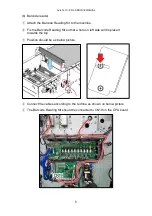
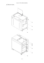
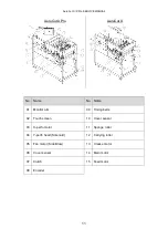
Page 9: ...AeroCut X XPro SERVICE MANUAL 9 d Remove covers ...

Page 10: ... Margin slitter unit 21 PCB I O board 06 Y perforator 22 PCB CPU board 07 X perforator 23 Servo amplifier 08 Barcode reading unit 24 PCB Sensor 09 Fan motor Suction 25 DC power supply 10 Feed belts 26 Feed table motor 11 Feed table 27 Micro switch Feed table lower limit 12 Feed sensor 28 Transformer 13 Fan motor Blow 29 LAN connector 14 PCB Ultra sonic sensor 30 Caster 15 Margin slitter motor 31 I...

Page 11: ...o Name No Name 01 Monitor arm 09 Timing belts 02 Touch screen 10 Cover sensor 03 X perfo motor 11 Sponge roller 04 Y perfo head Solenoid 12 Carrying roller 05 Fan motor Side Blow 13 Crease motor 06 Cover sensor 14 Main motor 07 Clutch 15 Feed motor 08 Encoder ...

Page 12: ...creen operation 3 1SERVICE MENU AeroCut XPro Press and hold the top left corner until hear a sound Press and hold the bottom left corner until the screen changes AeroCut X Click the upper left corner 5 times Click the upper left corner 5 times ...

Page 13: ...RVICE MANUAL 13 Double click the top left corner Enter the service password Enter the service password Program Version TP V stands for Version of the Touch screen image CPU V stands for Version of the CPU board program ...

Page 14: ...ll move to specified point mm Input moving distance of X Perfo blade mm Guillotine will move once Crease will move upper limit Crease will move lower limit X Perfo blade will move to initial position FEED TABLE will move upward while this is being pressed FEED TABLE will move downward while this is being pressed Go to SLITTER Operation Screen Go to INPUT DATA CHECK screen SV OFF the state where th...

Page 15: ...esents the state in which there is no sheet under the sensor while the number closer to zero indicates that thicker sheets have been detected by the sensor paper sheets are being loaded no paper sheets loaded Check operation of X Perfo Count times of operation Check operation of jump function of Y Perfo Count times of jumping Stop all operations Of note Cutter and Crease will move to the upper lim...

Page 16: ...ine will move once Crease will move upper limit Crease will move lower limit FEED TABLE will move upward while this is being pressed FEED TABLE will move downward while this is being pressed Go to SLITTER Operation Screen Stop all operations Of note Cutter and Crease will move to the upper limit Feed belt will rotate positively by pressing this once It will stop by pressing it again Feed belt will...

Page 17: ...an integer between 0 and 1023 The umber 1023 represents the state in which there is no sheet under the sensor while the number closer to zero indicates that thicker sheets have been detected by the sensor paper sheets are being loaded no paper sheets loaded Return to SERVICE MENU Screen ...

Page 18: ... Adjustments on the paper feed in Operation Manual 3 4SLITTER Operation Screen AeroCut XPro AeroCut XPro Values The values of Slitter s current positions are shown Slitters will move to the end while this is being pressed Slitters will move to the front while this is being pressed RETURN Return to Manual Operation Screen ...

Page 19: ...elded and turned on when transmitted The lamp on the screen will be turned on when shielded and turned off when transmitted C MARK SENS Cut mark sensor The sensor lamp orange will be turned on when detecting black color and turned off with no detection The lamp on the screen will be turned on when detecting black color and turned off with no detection How to adjust Page54 ...

Page 20: ...ll be turned on when shielded and turned off when transmitted The lamp on the screen will be turned on when shielded and turned off when transmitted How to adjust Page51 or Page53 AeroCut XPro AeroCut X CUTTER UP LMT SW The lamp on the screen will be turned on when the switch is on ...

Page 21: ... will be turned on when shielded and turned off when transmitted COVER SENS A B The sensor lamp will be turned off when shielded and turned on when transmitted The lamp on the screen will be turned off when shielded and turned on when transmitted DOUBLE FEED SENSOR The lamp on the screen will be turned off when shielded and turned on when transmitted ...

Page 22: ...e screen will be turned on when switched on FD TBL UP SENS The sensor lamp will be turned off when shielded and turned on when transmitted The lamp on the screen will be turned off when shielded and turned on when transmitted SERVO ALERT The lamp will be turned on if an error occurs on the servo motor the lamp stays off when no error condition exists no image ...

Page 23: ...o motor SLITTER ENCODER 1 4 A B These are encoders for detecting the positions of slitter motors CRSR UP SENS CRSR LW SENS The sensor lamp will be turned off when shielded and turned on when transmitted The lamp on the screen will be turned off when shielded and turned on when transmitted XPERFO ORIGIN SENS The lamp on the screen will be turned on when shielded and turned off when transmitted no i...

Page 24: ...o the machine It turns off when the harness is disconnected OP CONVEYER SENS The lamp on the screen light up when the sensor is closed The lamp on the screen light out when there is nothing on the sensor DOUBLE FEED ULTRA SONIC The lamp on the screen light up when there are two or more sheets of paper between the sensor The lamp on the screen light out when there are no paper or only one sheet of ...

Page 25: ...RNAL ERROR The lamp on the screen light up when the signal from the external equipment becomes HIGH The lamp on the screen light put when the signal from the external equipment becomes LOW RETURN Return to Manual Operation Screen no image ...

Page 26: ...ropriate language The language of the touch screen will switch on English is selected at the time of shipment Languages that are not available at present cannot be selected Password A password is set to switch between German and French please enter the password RETURN Return to Service menu Screen ...

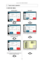
Page 27: ...AeroCut X XPro SERVICE MANUAL 27 3 7MAINTENANCE Screen AeroCut XPro AeroCut X ...

Page 28: ...utter Default setting do not change Paper vacuuming time when the feed table is lifted to the upper limit sec Distance between targeted positions and the points where slitter units start fine adjustment when changing slitter positions This is to set either mm or inch as the measurement input unit Go to Maintenance Screen 2 Return to Service menu Screen Total number of processed Guillotine times To...

Page 29: ...ns to inch the rollers forward backward and remove the jammed paper If paper is stuck around the guillotine section press CUTTER to cycle the guillotine to chop jammed paper AeroCut XPro AeroCut X Detach Sponge roller and Slitter cover if necessary and remove jammed paper Remove screws ...

Page 30: ...r in waste box before the waste bin becomes full It may cause paper strips remain inside the machine and cause paper jam Note If paper jam often occurs make sure that paper strip is not left in the indicated sections Inside of Slitter head Inside of Guillotine cover Inside of Crease AeroCut XPro AeroCut X Washer screw Waste box ...

Page 31: ...5 Replacement of parts 5 1Slitter Unit Operator side Remove Timing Belt from pulley Disconnect the harness Remove screws Inside Remove screws and cover Back side Loosen Idler and remove Timing Belt Disconnect the harness Remove screws ...

Page 32: ...t X XPro SERVICE MANUAL 32 Pull Slitter Units out Note Shaft and Screw shaft shown on below figure might get rusty if touched by bare hands Put gloves on hands when you detach slitter shaft Screw shaft Shaft ...

Page 33: ...AeroCut X XPro SERVICE MANUAL 33 5 2Slitter head Remove screws and cover Remove pulley and Retaining ring E Remove hexagonal shafts ...

Page 34: ...VICE MANUAL 34 Remove screws Note The Margin Slitter Unit and Gutter Slitter Unit have different numbers of pulley teeth Attention to the color of the mark when installing Margin Slitter Unit Gutter Slitter Unit RED BLUE ...

Page 35: ...o find the position where it sounds strange Please stop slitter head and loosen Bolts then tighten it again When Bolts is tighten please be careful not to make any space between Slitter moving nut and Bracket This space may happen slitter rattle so that it could make inaccurate cutting by slitter unit For more smooth movement of slitter unit please put some of silicone oil on screw shaft When it i...

Page 36: ...is in contact with the cutter unit This will be a mark for reattachment Remove the connector If the ionizer is original attached Remove screws and Guillotine Cover AeroCut XPro AeroCut X Remove the connector of the Guillotine from the main board Remove screws and pull Guillotine Unit out ...

Page 37: ...AeroCut X XPro SERVICE MANUAL 37 5 4X perforator blade Remove covers Move Perforation blade holder to the center by hand Be careful not to touch Perforation blade Perforation blade holder ...

Page 38: ...AeroCut X XPro SERVICE MANUAL 38 Remove blade by pulling Perforation blade holder down Note Attach Blade in shown way that blue rings should be together OK NG Perforation blade ...

Page 39: ...AeroCut X XPro SERVICE MANUAL 39 5 5Y perforator blade Remove covers Remove blades Note Blade is double sided ...

Page 40: ...AeroCut X XPro SERVICE MANUAL 40 5 6Feed belt Unit Remove screws and cover Disconnect the harness Remove clutch Only AeroCut X Pro ...

Page 41: ...ERVICE MANUAL 41 Feed belt unit can be removed after bolts are removed AeroCut XPro AeroCut X Note After mounting the feed unit ensure that the gap between clutches is 0 25 0 1 using a feeler gauge Feeler gauge Clutch ...

Page 42: ...roCut X XPro SERVICE MANUAL 42 6 Adjustment 6 1Settings 6 1 1 Feed settings a Default AeroCut XPro AeroCut X b Setting example Thin paper 120 250g Thick paper 250 350g VACUUM 5 10 BLOWER 10 10 BLOWER 5 10 ...

Page 43: ...g value when you finished adjustment AeroCut XPro Double click the bottom left corner Enter the service password AeroCut X Click the top right corner 5 times Enter the service password The values shown on the screen will be 0 after overwriting The 1 000 length magnification part will not become 1 000 by double clicking the top right corner will not be stored internally If you prefer to reset value...

Page 44: ...ligner by position of a hole in below picture when attaching the feed belt unit It is factory setting if Feed belt unit is attached so that a small hole contacts a big hole Hole position Status Default Factory Setting Parallel to Guide Effectiveness of Aligner High Low None Hole Guide ...

Page 45: ...AL 45 b Feed area mechanical adjustments 1 Lower Blower position Note Do not remove screws because blower will drop Blower base Blower Adjust the height by loosening screws Blower base Friction surface Range of Value H 0 5 1 0mm ...

Page 46: ...AeroCut X XPro SERVICE MANUAL 46 2 Separator position Separator Adjust the height by loosening screws Range of Value H 0 5 1 0mm Separator must be placed on higher position than friction surface ...

Page 47: ...eed belt unit position Adjust the height by loosening screws Adjust bolts This will be a mark for reattachment Lift and fix Feed belt unit with 2mm thick paper inserted as above figure Ensure that it is parallel to the Feed guide by sight ...

Page 48: ...ensor position When the feed table is upper dead point the proper gap between the feed table and the feed belt is 2 0 5mm 0 08 0 02 Loosen the screws and adjust the position of the feed sensor properly Screws Feed sensor Feed table Feed belts ...

Page 49: ...rts replacement etc the basement can be attached parallel by pressing the base against Locating metal plate Ensure that the basement is put on Locating metal plate when you detach it Please detach this part below in case that the upper surface of the basement is not parallel Locating metal plate Do not loosen this screw ...

Page 50: ...oCut X XPro SERVICE MANUAL 50 Settle a reference from two delivery rollers and adjust parallelism of the base with tolerance within 0 3 mm between A and B Difference between A and B should be within 0 3 mm ...

Page 51: ...ound 500 with 120gsm paper Checked to be over 40 with 350gsm paper b AeroCut X Volume Subject How to adjust VR4 Stop sensor Turn VR4 on CPU Board in clockwise with paper 77gsm When D20 on CPU board turns off turn VR4 in clockwise for two division from this position VR3 Origin sensor Turn the volume fully in clockwise VR2 Double feed sensor Detector Turn the volume fully in anticlockwise VR1 Double...

Page 52: ...O which is shown on MANUAL CONTROL screen VR7 X perforator Stopping setting After that adjust voltage to 0 100V by turning VR7 on I O Board without pressing any button VR1 X perforator Origin sensor Turn the volume fully in clockwise b AeroCut X Volume Subject How to adjust VR15 Input sensor Turn the volume fully in clockwise VR8 Unused Turn the volume fully in anticlockwise VR7 Unused Turn the vo...

Page 53: ...terclockwise without inserted and adjust it by turning it counterclockwise by about 1 extra scale from the position where D20 is lit VR1 Origin sensor Detector Turn it counterclockwise without inserted and adjust it by turning it counterclockwise by about 1 extra scale from the position where D3 is lit VR1 VR2 D20 D3 ...

Page 54: ... clockwise Please adjust with no paper under the sensor Attention to the lighting of the LED Both lights Still turn in clockwise The green turn off Still turn in clockwise The orange turn off too Still turn in clockwise Adjust turn on the green light again Check the operation by putting the paper with the cut mark printed under the sensor No paper White piece of paper Black piece of paper ...

Page 55: ...Ultra sonic sensor Turn the VR2 slowly in anticlockwise Match the place where the LED on the board turns from a weak light to a strong light Check the INPUT DATA CHECK screen lamp does not blink It must be lit AeroCut XPro AeroCut X Check the lamp turns on with two sheets of paper turns off with one sheet and turns off without paper VR2 VR1 Check the LED VR2 ...

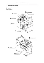
Page 56: ...AeroCut X XPro SERVICE MANUAL 56 7 How to make layout 7 1General template mm ...

Page 57: ...AeroCut X XPro SERVICE MANUAL 57 7 2General template inch ...

Page 58: ...0 PRESET 200 552 Prime A C P 0 9 001 552 One Velocity O XPro R X X Note If PRESET job is selected it is possible to run a job even if Machine No is different b How to print Barcode should be printed at almost the same level of Cut Mark and its length must be more than 5mm The width of barcodes must be within a range of 35mm to 45mm The center of a barcode should be put on 120mm from the further pa...

Page 59: ... window shows up input a number from a range of 0 to 9 as the Machine No if a user has several machines and every machine has different data This number should be used to identify multiple machines If it is not necessary to identify it does not matter if this Machine No is same Factory setting is 0 AeroCut XPro AeroCut X ...

Page 60: ...er to USERDATA No 3 digits and create 7 digits Barcode Ex If USERDATA No is 10 machine is Prime and Machine number is 0 Barcode should be ACP0010 According to the section 1 Detail of Barcode put the barcode on an artwork and print Set the prints and select Barcode Job Check or Barcode Job Change on the screen Then press the START Using barcode with Plug in Software After starting Illustrator or In...

Page 61: ... 210x297 PERFO 148 5 234 A4 210x297 PERFO 148 5 217 BUSINESS CARD 55x91 235 BUSINESS CARD 55x91 A3 A4 landscape NO Description NO Description 240 BUSINESS CARD 55x85 260 BUSINESS CARD 55x85 241 BUSINESS CARD 50x85 261 BUSINESS CARD 50x85 242 BUSINESS CARD 55x90 262 BUSINESS CARD 55x90 243 BUSINESS CARD 50x90 263 BUSINESS CARD 50x90 244 PHOTO L 88 9x127 264 PHOTO L 88 9x127 245 PHOTO 2L 127x178 265...

Page 62: ... 55x85 441 BUSINESS CARD 50x85 461 BUSINESS CARD 50x85 442 BUSINESS CARD 55x90 462 BUSINESS CARD 55x90 443 BUSINESS CARD 50x90 463 BUSINESS CARD 50x90 444 PHOTO L 88 9x127 464 PHOTO L 88 9x127 445 PHOTO 2L 127x178 465 PHOTO 2L 127x178 446 SRA3 320x450 466 LETTER 215 9x279 4 447 A3 297x420 467 LEDGER_DIV 3 448 A4 210x297 468 LEDGER_DIV 4 449 A5 148x210 469 LEGAL 215 9x355 6 450 A6 105x148 470 CD JA...

Page 63: ...PERFORATE 55 494 50x170 PERFORATE 55 514 50x170 PERFORATE 55 495 55x180 PERFORATE 55 515 55x180 PERFORATE 55 496 50x180 PERFORATE 55 516 50x180 PERFORATE 55 LETTER landscape LETTER portrait NO Description NO Description 520 BUSINESS CARD 55x85 540 BUSINESS CARD 55x85 521 BUSINESS CARD 50x85 541 BUSINESS CARD 50x85 522 BUSINESS CARD 55x90 542 BUSINESS CARD 55x90 523 BUSINESS CARD 50x90 543 BUSINESS...

Page 64: ...EGAL 8 5 x14 0 333 CD JACKET 4 7 x9 44 353 LETTER 8 5 x11 0 354 LABEL 4 25 x5 0 355 CD JACKET 4 7 x4 7 356 CD JACKET 4 7 x9 44 LEDGER LEGAL NO Description NO Description 360 BUSINESS CARD 2 x3 5 S 380 BUSINESS CARD 2 x3 5 S 361 BUSINESS CARD 2 x3 5 D 381 BUSINESS CARD 2 x3 5 D 362 BUSINESS CARD 3 5 x4 382 BUSINESS CARD 3 5 x4 363 PHOTO L 3 5 x5 0 383 PHOTO L 3 5 x5 0 364 PHOTO 2L 5 0 x7 0 384 PHOT...

Page 65: ...S CARD 3 5 x4 403 PHOTO L 3 5 x5 0 423 PHOTO L 3 5 x5 0 404 PHOTO 2L 5 0 x7 0 424 PHOTO 2L 5 0 x7 0 405 LETTER_DIV 2 425 POST CARD 3 0 x5 0 406 LETTER_DIV 3 426 POST CARD 3 5 x5 5 407 LETTER_DIV 4 427 POST CARD 4 0 x6 0 408 POST CARD 3 0 x5 0 428 POST CARD 8 0 x10 0 409 POST CARD 3 5 x5 5 429 LABEL 4 25 x5 0 410 POST CARD 4 0 x6 0 430 CD JACKET 4 7 x4 7 411 POST CARD 8 0 x10 0 412 LABEL 4 25 x5 0 ...

Page 66: ...AeroCut X XPro SERVICE MANUAL 66 8 Electricity related 8 1Equipment Electric circuit and parts AeroCut XPro ...

Page 67: ...AeroCut X XPro SERVICE MANUAL 67 AeroCut XPro ...

Page 68: ...AeroCut X XPro SERVICE MANUAL 68 AeroCut XPro ...

Page 69: ...AeroCut X XPro SERVICE MANUAL 69 AeroCut X ...

Page 70: ...AeroCut X XPro SERVICE MANUAL 70 AeroCut X ...

Page 71: ...AeroCut X XPro SERVICE MANUAL 71 AeroCut X ...

Page 72: ...ouble feed sensor Emitter 5 11 Stop sensor Emitter 6 12 XPro Sensor PCB 22 X Stop sensor Detector 7 10 Cut mark sensor 8 8 Origin sensor Emitter 9 9 XPro Sensor PCB 20 X Origin sensor Detector 10 3 LAN Board 11 2 Touch screen 12 19 Barcode scanner 13 13 Output to external equipment 14 5 Double feed sensor Detector 15 17 I O Board 50 16 16 I O Board 51 ...

Page 73: ... 6 67 Side blow motor 7 63 XPro Clutch X Feed belt motor 8 76 Jump perforation 1 solenoid 9 79 Conveyer stacker motor 10 62 Front blow motor 11 80 Ultra sonic PCB 01 12 61 Feed table motor 13 66 X perfo motor 14 58 Input sensor Emitter 15 59 Input sensor Detector 16 55 Conveyer stacker exist 17 60 Conveyer stacker sensor 18 53 Input to external equipment 19 52 20 50 CPU Board 17 21 51 CPU Board 16...

Page 74: ...r sens A 29 48 Slitter 1 motor 30 47 Slitter 2 motor 31 46 Slitter 3 motor 32 45 Slitter 4 motor 33 44 Cutter motor 34 40 Feed upper sensor 35 36 X perfo origin sensor Detector 36 43 Cutter limit switch 37 42 Feed table lower limit switch 38 41 Ultra sonic PCB 01 39 39 X perfo exist 40 38 Crease upper sensor 41 37 X perfo origin sensor Emitter 42 35 Crease lower sensor 43 34 Slitter 4 origin senso...

Page 75: ...ector CN Connection source 1 1 I O Board 41 80 2 2 Ultra sonic sensor Detector 3 3 Ultra sonic sensor Emitter Sensor PCB No Connector CN Connection source 1 20 CPU Board 09 2 22 CPU Board 12 3 24 Encoder 4 21 Origin sensor Detector 5 23 Stop sensor Detector ...

Page 76: ...OUTPUT Slitter 1 move inside OUTPUT Slitter 1 move outside OUTPUT Waste conveyer motor OUTPUT Slitter 2 move inside OUTPUT Slitter 2 move outside OUTPUT Slitter 3 move inside OUTPUT Slitter 3 move outside OUTPUT Slitter 4 move inside OUTPUT Slitter 4 move outside OUTPUT Cutter motor move reverse OUTPUT Cutter motor move forward OUTPUT External equipment ...

Page 77: ...UTPUT Crease motor move reverse D23 OUTPUT Crease motor move forward LED on Left Upper Side D48 INPUT None D40 INPUT External equipment D24 INPUT Conveyer stacker exist D42 INPUT Cutter upper limit switch D34 INPUT Feed table lower limit switch D26 INPUT Ultra sonic sensor D11 INPUT X perfo exist D4 INPUT Crease upper sensor D62 INPUT Cover limit switch B D59 INPUT Cover limit switch A D56 INPUT C...

Page 78: ... INPUT Slitter 3 encoder pulse A INPUT Slitter 3 encoder pulse B INPUT Slitter 2 encoder pulse A INPUT Slitter 2 encoder pulse B INPUT Slitter 1 encoder pulse A INPUT Slitter 1 encoder pulse B INPUT X perfo origin sensor INPUT Conveyer sensor INPUT Feed sensor INPUT Servo alert INPUT Servo positioned LED on Upper Side D35 INPUT Servo motor encoder pulse B D54 INPUT Servo motor encoder pulse A ...

Page 79: ...wer Supply for CPU TP2 24 V Power Supply for Touch screen TP3 24 V Input from DC Power Supply TP4 3 3V Power Supply for Pulse controller TP5 GND Ground TP6 24 V Power Supply for Sensors and Control Systems TP7 GND Ground TP8 5 V Power Supply for Slitter encoders TP9 GND Ground ...

Page 80: ...Board TP1 24 V Power Supply for Motors TP2 GND Ground TP3 24 V Power Supply for Sensors and Control Systems TP4 24 V Power Supply for None TP5 5V Power Supply for Slitter encoders TP6 GND Ground TP7 Variable Power Supply for Stepper motor ...

Page 81: ...AeroCut X XPro SERVICE MANUAL 81 8 5Wiring Details ...

Page 82: ...AeroCut X XPro SERVICE MANUAL 82 ...

Page 83: ... accessible via the following link Manual https www3 panasonic biz ac e dl manual index jsp series_cd 3514 Software https www3 panasonic biz ac e dl software index jsp series_cd 3514 Install the software according to the downloaded operating manual Connect the USB cable Type A mini B to the connector X1 for the driver to also install the USB driver For installation refer to the downloaded operatin...

Page 84: ...arameter to be read window is displayed Click Read from the file Click OK Of the data we provided select a data file with a file extension of prm5 and click OK Click Trans Click EEP after the transmission is completed to complete the entire process ...

Page 85: ...TA 7 8 10 CPU Pentium Ⅳ 1 GHz processor or equivalent Pentium 200 MHz processor or equivalent Memory 1 GB or more 256 MB or more Hard disk space 340 MB or more 100 MB or more Display 1024 768 screen 16 bit high color or better 1024 768 screen minimum 800 600 screen Interface USB port USB port 9 1 2 Confirmation of Accessories Program writer USB cable Type A B CD R ...

Page 86: ... Touch screen for XPro Insert DISK in the CD DVD drive and install it according to the following procedure The procedure below is for WINDOWS XP Double click on VTTransferTool for prime XPro screen VTTGHp6 exe of the CD DVD Select a language OK Next Next Install Finish ...

Page 87: ...AeroCut X XPro SERVICE MANUAL 87 9 1 4 How to install AVR STUDIO The procedure below is for WINDOWS XP Double click on AVR_TOOL AvrStudio4Setup exe of the CD Next I accept Next Install Next Next ...

Page 88: ...AeroCut X XPro SERVICE MANUAL 88 Next is the update of AVR STUDIO Double click on AVR_TOOL AVRStudio4 18SP3 exe of the CD Finish Next Finish ...

Page 89: ...AeroCut X XPro SERVICE MANUAL 89 Next is the installation of WINAVR Double click on AVR_TOOL WinAVR 20100110 install install exe of the CD OK Next I Agree Next Install Finish Select a language ...

Page 90: ...eroCut X XPro SERVICE MANUAL 90 If the OS of the PC is Windows 8 or 10 install this driver Double click on win8_10_atmel_driver driver atmel bundle 7 0 888 exe of the CD Close the Window I agree Install ...

Page 91: ...u2 with a file extension of mu2 For X The data is in the gt_data folder There is a folder AEROCUT_X_V100 in the gt_data folder The figure 100 refers to a version which means Version 1 00 Save this data in a folder of your choice in your computer and upgrade the version as follows AeroCut XPro The procedure below is for WINDOWS XP Open the touch screen cover and connect to the USB as shown in the f...

Page 92: ...f the installation of the USB driver is necessary at this point install the driver Select the one at the bottom Next Select the one at the bottom Next Select the one at the top Next Next Finish Start up the computer and double click on Click on Send screen data ...

Page 93: ...which you saved our screen data select a file with a file extension of ms2 and click on Send all data Click on Yes Click YES if a question Version of system program is new Send to VT unit is asked If the question is not asked you do not need to do anything ...

Page 94: ...p sound when the transmission has completed Click OK and finish by pressing Exit After your installing updated software the direction you can see the below will remain on the touch screen After seeing that words on the screen turn off the machine and turn it on again ...

Page 95: ... AeroCut X Write to the SD card for each gt_data folder sent Turn on Remove the touch screen cover and insert the SD card into the back of the Touch screen The screen shown below will change automatically Click on SD GT Click on Copy ...

Page 96: ...ERVICE MANUAL 96 Click on OK Please wait for a while until it is completed Click on OK when done Touch screen will restarted automatically After seeing that words on the screen turn off the machine and turn it on again ...

Page 97: ...ers to a version which means Version 1 00 Save this data in a folder of your choice in your computer and upgrade the version as follows The procedure below is for WINDOWS XP Remove the front cover and then the electrical component cover Connect the accessory of USB cable with Program writer Connect the connector of Program writer to CN7 on the CPU board Must be connected the red wire of the connec...

Page 98: ...NUAL 98 If the installation of the USB driver is necessary at this point install the driver following the procedure below Next Finish Next Select the one at the bottom Check the second one Next Next Select the one at the bottom ...

Page 99: ...UAL 99 Start up the computer and double click on Start Program Atmel AVR Tools AVR Studio 4 Click on Cancel Click on AVR Connect to the Selected AVR Programmer Select AVRISP mkⅡ for Platform Select USB for Port click on Connect ...

Page 100: ...firmware upgrade is necessary If the warning does not appear on the screen skip to How to upgrade a Click on OK b Click on Start Upgrade c Disconnect the USB cable of Program writer and connect it again d After that click on OK If AVR STUDIO has shut down return to and conduct the operation again ...

Page 101: ... tab and on Settings Select 500 kHz for ISP Freq click on Write and click on Close After clicking on Program tab select the folder where the file was initially saved as the save location Click on Select where our hex file was initially saved By clicking on Program the transmission of the program will start About 30 sec ...

Page 102: ...ab and click next to No memory lock features enabled then select Further programming and verification disabled Click on program The process is completed when the transmission of the program has finished From the next time onward proceed in the order of and ...

Page 103: ...ANUAL 103 10 Cleaning greasing Clean Rollers and Sensors properly Rollers ahead and behind of Guillotine may affect accuracy if they are dirty Stop sensor mirror may cause inoperativeness if it is dirty AeroCut XPro AeroCut X ...

Page 104: ...61 061 For Y perfo F Blade receiver 7711 0410 For Y jump perfo Y perfo G Blade receiver 7703 0531 1 For X perfo Guillotine 61 045 1 Timing belt For Carrying roller 82 546 1 S3M 1146 For AeroCut XPro Timing belt For Carrying roller 82 543 1 S3M 957 For AeroCut X Timing belt For Carrying roller 82 565 1 S3M 741 Timing belt For Carrying roller 82 547 1 S3M 528 Timing belt For Main motor 82 562 1 S3M ...

Page 105: ...AeroCut X XPro SERVICE MANUAL 105 Timing belt For Slitter 82 557 4 S3M 216 Feed belt 80 718 4 L750 Timing belt For Feed belt motor 82 544 1 S3M 174 ...

Page 106: ...eld plate may be wrong Page19 I O Board may be out of order CPU Board may be out of order Wire breakage or connection failure may have occurred 2 This occurs when the unit was started with paper still remaining inside the unit If the screen below remains after paper removal Clean the reflector under the Stop Sensor Page103 Either Origin Sensor C M Sensor or Stop Sensor may be out of order Page19 C...

Page 107: ...er Wire breakage or connection failure may have occurred When Carrying roller is not rotating Servo Motor and or Driver may be out of order CPU Board may be out of order Wire breakage or connection failure may have occurred 4 This occurs when the paper did not pass between Origin Sensor and Stop Sensor within a designated period of time If this frequently occurs When Feed Roller is rotating Paper ...

Page 108: ...nside of the machine Paper double feeding Paper thickness is out of specification Cutter blade may be blunt Cutter Motor may be out of order Switch CUTTER UP LMT SW may be out of order Page19 I O Board may be out of order CPU Board may be out of order Wire breakage or connection failure may have occurred When Crease is overloaded Paper tip could remain inside of the machine Paper double feeding Pa...

Page 109: ... detected Cut Mark printing density needs to be checked Cut Mark Sensor needs to be re adjusted Page54 Cut Mark Sensor may be out of order CPU Board may be out of order Wire breakage or connection failure may have occurred 9 Two or more sheets are fed at one time If this occurs frequently Fan out the paper sufficiently and jog the paper to make the each of the sheets separately Adjust the volume o...

Page 110: ...PU Board may be out of order Wire breakage or connection failure may have occurred 13 This occurs at times that machine is operated when Cutter is not on bottom dead center If this occurs frequently Sensor CRSR UP SENS may be out of order Page19 I O Board may be out of order CPU Board may be out of order Wire breakage or connection failure may have occurred 14 This occurs when the harness of X per...

Page 111: ...e origin sensor of X perfo Page19 Malfunction of X Perfo I O Board may be out of order CPU Board may be out of order Wire breakage or connection failure may have occurred 17 This occurs when barcode cannot be read If this occurs frequently Check if barcode is printed clearly and is clean Check if the position of barcode is correct Tipping the Barcode scanner unit can improve accuracy of reading Ma...

Page 112: ...curs frequently Fan out the paper sufficiently and jog the paper to make the each of the sheets separately Adjust the volume of Blower FAN and Vacuum FAN Blow motor may be out of order Note Activate double feed detection mode 23 A sheet stops after moving slightly with noise Thick paper cannot be fed at higher speed and a sheet stop being fed with noise Please slow down the speed 24 Paper jam occu...

Page 113: ...UCHIDA YOKO CO LTD TOKYO JAPAN ...

Reviews: