background image

UgCS SkyHub

User Manual

integrated.ugcs.com
November 2021

Revision 5

Summary of Contents for SkyHub

Page 1: ...UgCS SkyHub User Manual integrated ugcs com November 2021 Revision 5...

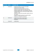
Page 2: ...anged the True Terrain Following description Changed the PERGAM_FALCON FREQUENCY_HZ description Changed the PERGAM_LMM FREQUENCY_HZ description Removed the RadSys RadSys Zond Lite support Removed supp...

Page 3: ...tion Changed default Payload and Autopilot plugins loading settings to false Updated the RadSys Zond description related to the new Lite version Updated the desktop application using description Updat...

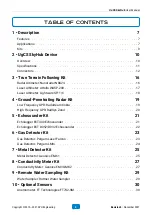
Page 4: ...gh Frequency GPR RadSys Zond 21 5 Echosounder Kit 21 Echologger ECT400 Echosounder 22 Echologger ECT D052 D032 Echosounder 23 6 Gas Detector Kit 23 Gas Detector Pergam Laser Falcon 24 Gas Detector Per...

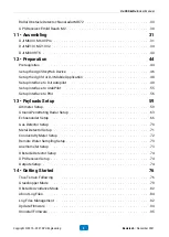
Page 5: ...59 13 Payloads Setup 59 Altimeter Setup 63 Ground Penetrating Radar Setup 66 Echosounder Setup 70 Gas Detector Setup 71 Metal Detector Setup 72 Conductivity Meter Setup 73 Remote Water Sampling Setup...

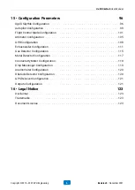
Page 6: ...Gas Detector Configuration 117 Metal Detector Configuration 118 Conductivity Meter Configuration 119 Drop Messenger Configuration 120 Anemometer Configuration 120 Obstacle Detector Configuration 121 G...

Page 7: ...d and ESD protected external interfaces Reliable and convenient connectors with lock ideal for airborne applications 12 V power output with switch off function for payload connecting 3 UART 1x RS 232...

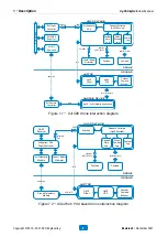
Page 8: ...oad Monitor Wi Fi USB UART RS232 Figure 1 1 DJI SDK drone interaction diagram Ardupilot PX4 Flight Controller GNSS Receiver Air Telemetry Module Telemetry Port UART Laser Radio Altimeter Onboard Softw...

Page 9: ...es the UgCS SkyHub device cables and related software One may extend the UgCS SkyHub solution capabilities by adding custom payloads using UgCS SkyHub SDK Find more details here https github com ugcs...

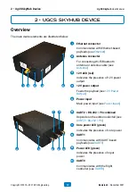
Page 10: ...ut Feeds the payload see 12V Power Output 5 Power input Main power input see Power Input 5 4 10 8 6 9 7 6 UART2 RS 232 I C combined Depends on the edition selected see UART2 RS 232 I C 7 Core power LE...

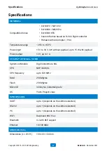
Page 11: ...le Digi ConnectCore 6UL CPU NXP i MX6UL CPU frequency up to 528 MHz RAM 256 Mbytes Flash 256 Mbytes MicroSD 32 Gbytes industrial grade OS Yocto Project Linux Interfaces UART up to 3 depends on the edi...

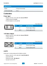
Page 12: ...y ground 12V Power Output Mating connector on the cable side Amass XT30U M Voltage 12 V 1 Current up to 1 A 1 2 Pinout device side Pin Name Description 1 12V Power output voltage 2 GND Power output gr...

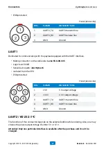
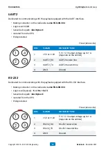
Page 13: ...protected 1 2 3 4 5 Pinout device side Pin Name Description 1 5V 5 V output voltage 2 3V3 3 3 V output voltage 3 UART1_TX UART1 transmit line 4 UART1_RX UART1 receive line 5 GND Ground UART2 RS 232 I...

Page 14: ...RT2_TX UART2 transmit line 4 GND Ground RS 232 Dedicated to communicating with the payload equipped with the RS 232 interface Mating connector on the cable side Lemo FGG 0B 304 Logic level typical 5 4...

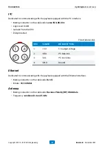
Page 15: ...1 5V 5 V output voltage 2 SDA I C data line 3 SCL I C clock line 4 GND Ground Ethernet Dedicated to communicating with the payload equipped with the Ethernet interface Mating connector on the cable si...

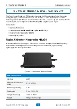
Page 16: ...ware SF11 C or Radar altimeter Nanoradar NRA24 Mounting kit cables Radar Altimeter Nanoradar NRA24 Nanoradar NRA24 is the compact K band radar altimeter It adopts 24GHz ISM frequency band with the adv...

Page 17: ...improved accuracy at lower repetition rates with a variety of filtering and averaging features Figure 3 2 Attollo WASP 200 altimeter Specifications Interface UART Effective measurement range 0 2 m to...

Page 18: ...es per second includes serial I C and USB interfaces Figure 3 3 Lightware SF11 C altimeter Specifications Interface I C UART USB Effective measurement range 0 m to 120 m Measuring accuracy 10 cm Power...

Page 19: ...is more appropriate for detecting large objects soil profiling bathymetry It is characterized by larger penetrating depth and larger detectable object dimensions Figure 4 1 Low frequency GPR Specific...

Page 20: ...t detection surface layer soil profiling Figure 4 2 High Frequency GPR Specifications Center frequency 1000 MHz 500 MHz 500 MHz Aero version Frequency range 600 MHz to 1300 MHz 200 MHz to 900 MHz 200...

Page 21: ...Echologger ECT400 is one of the smallest and lightest precision echosounders capable of measuring both accurate backscatter and depth data Figure 5 1 Echologger ECT400 with housing mounting kit and c...

Page 22: ...200 kHz Interface RS 232 RS 232 Effective measurement range 1 0 200m 50kHz 0 5 200m 200kHz 1 5 200m 30kHz 0 5 200m 200kHz Measuring accuracy 0 2 of the depth 0 2 of the depth Set sound speed 1500 m s...

Page 23: ...Pergam LMm Anemometer optional Anemometer FT Technologies FT742 SM Mounting kit and cable Gas Detector Pergam Laser Falcon Laser Falcon is a laser type methane gas detector Weight of the product allo...

Page 24: ...ointing the laser beam at the studied area Figure 6 2 Pergam LMm Specifications Interface UART Effective measurement range 1 ppm m to 50000 ppm m Measuring accuracy 10 Detection distance 0 5 m to 30 m...

Page 25: ...the detection of both ferrous and non ferrous metal Insensitive to common sources of both geologic and cultural noise the metal detector can be operated without compromise to data quality in most sur...

Page 26: ...Specifications Temperature range 30 C to 60 C 7 Metal Detector Kit UgCS SkyHub User Manual Copyright 2019 2021 SPH Engineering 26 Revision 5 November 2021...

Page 27: ...bility components within two distinct depth ranges simultaneously Geonics EM38 MK2 measures data without any requirement for soil to instrument contact Figure 8 1 Geonics EM38 MK2 Specifications Measu...

Page 28: ...02 ppt Data output RS232 USB USB RS232 adapter required Bluetooth Power source 9 V battery external 12 battery Device dimensions L W x H 107 x 17 x 8 cm Weight 5 4 kg with mountings and SkyHub Tempera...

Page 29: ...th True Terrain Following Kit Water sampler Ruttner Water Sampler Mounting kit and cable Water Sampler Ruttner Water Sampler Ruttner Water Sampler is TODO TODO Photo Specifications 9 Remote Water Samp...

Page 30: ...M2 or other GPS receiver with NMEA output data Anemometer FT Technologies FT742 SM FT Technologies FT742 SM is TODO Radar Obstacle Detector Nanoradar MR72 Nanoradar MR72 TODO GPS Receiver Emlid Reach...

Page 31: ...DJI M300 RTK DJI M600 M600 Pro UgCS SkyHub Device 1 Put the M600 brackets to UgCS SkyHub Figure 11 1 UgCS SkyHub with mounting brackets for M600 2 Mount the UgCS SkyHub onto the drone and connect the...

Page 32: ...r unless you are sure about the payload s power voltage range Figure 11 3 Connecting the UgCS SkyHub to power 4 Connect the UgCS SkyHub to the flight controller s API port using included interface cab...

Page 33: ...Figure 11 4 Connecting the UgCS SkyHub to the flight controller 11 Assembling UgCS SkyHub User Manual Copyright 2019 2021 SPH Engineering 33 Revision 5 November 2021...

Page 34: ...rews will be used to fix the customized cable cover in place Figure 11 5 M210 API and Power connectors 2 Snap the UgCS SkyHub on the right leg of the drone Figure 11 6 UgCS SkyHub on the M210 leg DJI...

Page 35: ...embly onto the rear right propeller arm Ensure that the gray UgCS SkyHub connectors are on the UgCS SkyHub side Figure 11 8 Wire assembly 5 Put the 3 pin rectangular connector through the hole in the...

Page 36: ...e drone The white stripe is on the top Figure 11 10 3 pin rectangular connector plugged into the drone 7 Push the cable cover over the connector making sure that the connector is fully seated DJI M210...

Page 37: ...rom the original Figure 11 12 M210 cable cover installed 9 Make the connections to the UgCS SkyHub Attention The data connectors have a different number of pins Be sure to use the appropriate connecto...

Page 38: ...he power cable into the drone Figure 11 14 Power cable connected to the M210 11 The installation is complete The end result is shown on the Figure 11 15 DJI M210 M210 V2 UgCS SkyHub User Manual Copyri...

Page 39: ...Figure 11 15 The UgCS SkyHub mounted onto the M210 drone DJI M210 M210 V2 UgCS SkyHub User Manual Copyright 2019 2021 SPH Engineering 39 Revision 5 November 2021...

Page 40: ...kyHub with mounting brackets data and power cable and radio altimeter Figure 11 16 DJI M300 RTK UgCS SkyHub TTF kit 2 Snap the UgCS SkyHub on the right leg of the drone DJI M300 RTK UgCS SkyHub User M...

Page 41: ...placed under rubber cover from the top right drone side Fix the cable bracket on the top of on M300 with M3 screw Connect XT30 connector to UgCS SkyHub power in port and 3pin Lemo connector to 3 pin...

Page 42: ...00 4 Attach altimeter to the right M300 leg under the UgCS SkyHub Connect 5pin Lemo connector to 5 pin UgCS SkyHub port Figure 11 19 Altimeter attached to the M300 DJI M300 RTK UgCS SkyHub User Manual...

Page 43: ...on is complete The end result is shown on the Figure 11 20 Figure 11 20 The UgCS SkyHub mounted onto the M300 drone DJI M300 RTK UgCS SkyHub User Manual Copyright 2019 2021 SPH Engineering 43 Revision...

Page 44: ...I drones For DJI A3 M600 M600 Pro DJI GO For DJI M210 M210 V2 M300 RTK DJI Pilot UgCS for DJI v2 30 or higher referred below as UgCS for DJI Connect to UgCS SkyHub Using Wi Fi Important It is strongly...

Page 45: ...ent to access the UgCS SkyHub file system For example one may use WinSCP Figure 12 1 WinSCP settings While pressing the Login button one may choose between login via SCP to have access to the file sys...

Page 46: ...iguration only after it enabling and UgCS SkyHub restart For example DJI autopilot related parameters are collected within the DJI section DJI APP_ID 1071019 APP_KEY 42873781474d507ebf72353187ea0af50c...

Page 47: ...AR_MR false NANORADAR_NRA true PAYLOAD_EXAMPLE false PERGAM_FALCON false PERGAM_LMM false RADARTEAM_COBRA false RADSYS_ZOND true For a more detailed description of the configuration file see Configura...

Page 48: ...DJI mobile application After starting the application go to Menu Drone Specific Settings and enable the corresponding checkbox Figure 12 2 Enable Custom Payload checkbox Setup the UgCS for DJI Mobile...

Page 49: ...Using Default Credentials Recommended It is recommended to use default credentials provided with the software pack Login app djidev com Password request when ordering the kit 1 Connect the DJI flight...

Page 50: ...ppear open the main window then choose the SDK tab and check Enable API Control and Ground Station Status checkboxes Figure 12 5 Enable API control in DJI Assistant 2 Setup Interface to DJI Autopilot...

Page 51: ...ative way to activate the Multiple Flight Mode is to go to the DJI GO app Camera View Enable Multiple Flight Mode 6 Switch on the DJI Remote Controller run DJI GO DJI Pilot choose Me tab press Login b...

Page 52: ...activate from the first attempt If there is no connection with flight controller after full system setup try to repeat steps from 8 to 10 several times with the drone power cycling Option 2 Using Use...

Page 53: ...se values to corresponding configuration fields in skyhub conf APP_ID and APP_KEY accordingly in DJI section as described in Setup the UgCS SkyHub Device Do not forget to restart the UgCS SkyHub after...

Page 54: ...is no connection with flight controller after full system setup try to repeat steps from 7 to 9 from the previous section several times with the drone power cycling Setup Interface to DJI Autopilot Ug...

Page 55: ...the following settings Figure 12 11 ArduPilot VSM configuration file 3 Make sure that vehicle ardupilot custom_payload onboard component_id is equal to the COMPONENT_ID value in the MAV section of th...

Page 56: ...ditor with administrator priveleges the file is located in the UgCS installation folder Find uncomment and adjust if needed the following settings Figure 12 12 PX4 VSM configuration file 3 Make sure t...

Page 57: ...nk and set parameter MAV_1_CONFIG to TELEM2 Figure 12 13 UgCS SkyHub PX4 TELEM2 port configuration 7 Restart autopilot 8 After restart data forwarding for TELEM2 autopilot telemetry ports should be en...

Page 58: ...ubscribes to the following MAVLINK messages GPS2_RAW 10 Hz GPS_RAW_INT 10 Hz GLOBAL_POSITION_INT 10 Hz ATTITUDE 10 Hz SYSTEM_TIME 1 Hz HEARTBEAT 1 Hz DISTANCE_SENSOR 1 Hz Setup Interface to PX4 UgCS S...

Page 59: ...y Meter Setup Geonics EM38 MK2 Setup Anemometer Setup FT Technologies FT742 SM Setup Obstacle Detector Setup Nanoradar MR72 Setup Outputs Setup GPS Output Setup Altimeter Setup There are common altime...

Page 60: ...zero level above ground when the drone stands at the surface ALTIMETER ZERO_LEVEL_M 0 4 The ZERO_LEVEL_M value will be subtracted from the distance reported by the rangefinder resulting in the true d...

Page 61: ...starts to measure the altitude only after takeoff Move the drone by hands before a flight to be sure the altimeter operates well See the Nanoradar NRA24 Altimeter Configuration section to find all av...

Page 62: ...as an UART interface LIGHTWARE_SF CONNECTION_TYPE I2C or CONNECTION_TYPE UART 3 Choose the appropriate SERIAL_DEVICE in the LIGHTWARE_SF section if the UART connection type has been chosen Set it to d...

Page 63: ...ME_RANGE parameters in the RADARTEAM_COBRA section according to concrete GPR model used RADARTEAM_COBRA MODEL SE 150 TIME_RANGE_NS 800 See Low Frequency GPR Configuration to find all available setting...

Page 64: ...using the desired mode time range sample count Figure 13 1 Prism 2 setup window 2 While using dual channel GPR model one may choose either single channel or dual channel mode by setting the MODE param...

Page 65: ...LAY_1 and TIME_RANGE_NS_1 4 While using dual channel mode one may setup the antenna offsets in the corresponding fields RADSYS_ZOND OFFSET_FORWARD_M_1 0 1 10 cm alongside the heading line OFFSET_FORWA...

Page 66: ...from the echosounder s value and the current altitude using the specified cable length parameter The True Depth value is recorded as a separate column in the position log file and echosounder NMEA lo...

Page 67: ...A log file should be recorded The ECHOSOUNDER mode is used to record both NMEA and SEG Y logs ECHOLOGGER_ECT MODE NMEA or MODE ECHOSOUNDER Note the data rate in the ECHOSOUNDER mode is significantly l...

Page 68: ...DEADZONE_LOW_MM parameters in the ECHOLOGGER_DUAL section according to the water body to be explored ECHOLOGGER_DUAL DEADZONE_HIGH_MM 500 DEADZONE_LOW_MM 1000 RANGE_HIGH_M 10 RANGE_LOW_M 10 5 Set the...

Page 69: ...e SAMPLING_RATE_HZ parameter in the ECHOLOGGER_DUAL section according to the table below The SAMPLING_RATE_HZ is relevant only for the ECHOSOUNDER mode Table 13 3 Sampling rate depending on the range...

Page 70: ...LEVEL_PPM value will be subtracted from the gas concentration reported by the gas detector resulting in the true gas concentration Pergam Laser Falcon Setup 1 Set PERGAM_FALCON item to true in PAYLOAD...

Page 71: ...er minimum and maximum values correspond to your needs METAL_DETECTOR MIN_OUTPUT_VALUE_MV 0 MAX_OUTPUT_VALUE_MV 1000 These values are used to bound valid metal detector values When the output value is...

Page 72: ...NECTION_TYPE in the GEONICS_EM_38_MK2 section GEONICS_EM_38_MK2 CONNECTION_TYPE BLUETOOTH connection through bluetooth or CONNECTION_TYPE RS232 connection through RS323 3 Choose the appropriate CHANNE...

Page 73: ...eter Setup There are common anemometer settings in the ANEMOMETER section Check whether minimum and maximum values correspond to your needs ANEMOMETER MIN_WIND_SPEED_MPS 0 MAX_WIND_SPEED_MPS 10 These...

Page 74: ...NSS plugin supports parsing for ZDA and GGA sentences of NMEA format 1 Set GNSS item to true in PAYLOADS section PAYLOADS GNSS true Important GPS Receiver loads settings from separate config file The...

Page 75: ...ected serial device name which the GPS output sends messages to 3 Choose the appropriate FREQUENCY_HZ and BAUD_RATE in the OUTPUT_GPS section See the GPS Output Configuration section to find all avail...

Page 76: ...additional options Disconnect from the UgCS SkyHub 2 Start the PC and connect it to the Wi Fi network Start the UgCS and plan a mission for the drone 3 Turn on the drone the payload and UgCS SkyHub d...

Page 77: ...Upload the route to the drone After that click the Read button in the Terrain Following widget UgCS CPM then click Configure and make sure the Terrain Following ENABLED message appears in the UgCS CP...

Page 78: ...oads Setup 5 Erase old log files if they are not more needed see Log Files Management below for details 6 Connect both the PC and the mobile device to the same Wi Fi network 7 Switch on the drone and...

Page 79: ...on the DJI Remote Controller must be obligatory switched back to P mode before manually control Otherwise the drone returns to an unexpected resuming point 18 If the drone descends below the minimum a...

Page 80: ...ton in the Grasshopper widget UgCS CPM then click Configure and make sure the Grasshopper ENABLED message appears in the UgCS CPM log window at the bottom side If not toggle the flight mode switch to...

Page 81: ...ng Gently shake the drone by hand until the altitude starts to change Note the altitude limits may be changed in Settings Altimeter window 10 Upload the route to the drone using UgCS 11 Go to the Gras...

Page 82: ...ght according to recommendations in the step 17 19 After the mission has been completed the drone stops at the last waypoint then climbs to increase its altitude to value defined the FAIL_SAFE_ALTITUD...

Page 83: ...CPM shows current safety action on the Obstacle Avoidance widget Usage 1 Connect to UgCS SkyHub see Connect to UgCS SkyHub Using Wi Fi or Connect to UgCS SkyHub Using Ethernet and set desired paramete...

Page 84: ...acle Avoidance mode is available any time 16 After flights has been completed return the drone to the desired landing position and land Press the Deactivate button on the Obstacle Avoidance widget Abo...

Page 85: ...fter taking off The system log begins after onboard software is started The logs with the same file names have been created simultaneously When the filename is to be changed e g after the time synchro...

Page 86: ...ion Common Elapsed ms Time elapsed since launch Date Date received from the drone Format yyyy MM dd Time Time received from the drone Format hh mm ss ms Pitch deg Pitch angle received from the drone R...

Page 87: ...asured altitude ALT Filtered Altitude m Altitude after applying LPF see Altimeter Configuration Table 14 4 Position Log Conductivity Meter Columns Description Colunm name Unit Description Conductivity...

Page 88: ...ation paramater Support for dual frequency echosounder ECHO True Depth Lo m Depth on low acoustic frequency with taking into account sensor position relative to the waterline True Depth Hi calculates...

Page 89: ...ot enough reflection very low intensity value is not accurate 6 too much reflection high density gas 7 too much reflection not able to measure by interfering of sunlight etc 8 N A 9 stop no measuring...

Page 90: ...ns mean sea level below ellipsoid Table 14 8 Position Log Ground Penetrating Radar Columns Description Colunm name Unit Description Ground Penetrating Radar GPR Trace Trace number in SEG Y file Table...

Page 91: ...Detector OBS Sector1 m Distance to the nearest obstacle in the sector 1 OBS Sector2 m Distance to the nearest obstacle in the sector 2 OBS Sector3 m Distance to the nearest obstacle in the sector 3 Ab...

Page 92: ...textbox 7 Press the Download button and wait for downloading has been finished 8 After the log files are not more needed you may delete them all using the Erase All button 9 If you need to delete only...

Page 93: ...Figure 14 4 UgCS CPM Manage Logs window Log Files Management UgCS SkyHub User Manual Copyright 2019 2021 SPH Engineering 93 Revision 5 November 2021...

Page 94: ...The latest UgCS SkyHub firmware compatible with the installed UgCS CPM is located in UgCS CPM firmware folder Also the latest UgCS SkyHub firmware is available here https integrated ugcs com dl s sky...

Page 95: ...are to MicroSD root path run media mmcblk1p1 by FTP SCP client 4 Connect to UgCS SkyHub via ssh and move to the MicroSD root 5 Unpack the firmware package and manually run the script to uninstall the...

Page 96: ...g by file size MB LOG_SPLIT_TIME_S 0 Period of log splitting s LOG_SPLIT_TRACES 0 Log splitting by trace number applicable to GPR and echosounder only LOG_SPLIT_WAYPOINTS 0 Log splitting by waypoint c...

Page 97: ...uttner water sampler Set to true if used ECHOLOGGER_DUAL false Using the Echologger ECT D052 D032 echosounder Set to true if used ECHOLOGGER_ECT false Using the Echologger ECT400 echosounder Set to tr...

Page 98: ...MM false Using the Pergam LMM gas detector Set to true if used RADARTEAM_COBRA false Using the Radarteam Cobra low frequency GPR Set to true if used RADSYS_ZOND false Using the RadSys Zond 12e high fr...

Page 99: ...device ArduPilot PX4 Configuration Table 15 4 ArduPilot PX4 connection settings Parameter Default Value Description MAV BAUD_RATE 57600 UART baud rate bps CONNECTION_TYPE UART Connection type UART to...

Page 100: ...ystem Id of UgCS SkyHub TELEMETRY_RATE 10 Telemetry frequency Hz V2_EXTENSION false Using MAVLink V2_EXTENSION messages Set to true to enable it Autopilot Configuration UgCS SkyHub User Manual Copyrig...

Page 101: ...r Configuration Table 15 6 GH settings Parameter Default Value Description GH ALTITUDE_SOURCE ALTIMETER ALTIMETER Use external altimeter as altitude source AUTOPILOT Use autopilot as altitude source D...

Page 102: ...ches to ARMED m s ALTITUDE_SOURCE ALTIMETER ALTIMETER Use external altimeter as altitude source AUTOPILOT Use autopilot as altitude source Attention Be careful using AUTOPILOT the altitude calculates...

Page 103: ...ate m s s Recommended range is from 1 0 to 20 0 POS_P 0 4 Proportional term of the PID position controller m s The higher value the faster the vehicle approaches to the waypoint Recommended range is f...

Page 104: ...ues may lead to oscillation and instability VEL_Z_P 0 2 Defines a proportional gain that compensates for an error between vertical target and actual velocities Recommended range is from 0 0 to 1 0 Not...

Page 105: ...size STD Determines how many standard deviations can me accepted before mesurments may be considered as invalid Available values 1 0 10 0 EF_FILTER_PROC_NOISE 0 5 Process noise for terrain offset m s...

Page 106: ...ttymxc1 for UART2 4 pin Attollo WASP 200 Altimeter Configuration Table 15 11 Attollo WASP 200 altimeter settings Parameter Default Value Description ATTOLLO_WASP AVERAGING 8 Averaging factor The more...

Page 107: ...I2C for I C connection UART for serial connection I2C_DEVICE_ADDRESS 0x66 I C device address in hexadecimal notation UART_BAUD_RATE 115200 UART baud rate bps SERIAL_DEVICE dev ttymxc5 UART serial dev...

Page 108: ...older devices High Frequency GPR Configuration Table 15 14 High Frequency GPR settings Parameter Default Value Description RADSYS_ZOND FILTER_1 OFF High pass filter for the first channel OFF High pass...

Page 109: ...ffset of the second antenna alongside the heading line m OFFSET_RIGHT_M_1 0 Offset of the first antenna alongside the traverse line m OFFSET_RIGHT_M_2 0 Offset of the second antenna alongside the trav...

Page 110: ...1 300 Trace time range for the first channel ns 50 100 200 300 500 800 1200 2000 This parameter is also applicable in single channel mode and with the Aero version Trace time range for the Aero versio...

Page 111: ...Description ECHOLOGGER_ECT ALT_THRESHOLD_PCT 10 Altimeter threshold in percents of a full scale BAUD_RATE 115200 UART baud rate bps DEADZONE_MM 300 Near field zone where detection is ignored mm FREQU...

Page 112: ...er used for debugging only SERIAL_DEVICE dev ttymxc1 Serial device name Use UART2 4 pin only START_DELAY_S 45 Start delay s TXLENGTH_US 50 Transmitted pulse length micro second The value is automatica...

Page 113: ...for high acoustic frequency dB GAIN_LOW_DB 0 Amplifying gain for low acoustic frequency dB MAX_SENSOR_ANGLE_DEG 10 Data filtering by tilt The data are not recorded if the sensor tilt value is greater...

Page 114: ...under used for debugging only SAMPLING_RATE_HZ 100000 Internal ADC sampling frequency Hz The sampling rate is relevant only for the ECHOSOUNDER mode Only fixed ranges are available 100000 50000 25000...

Page 115: ...dev ttyUSB0 UART serial device The built in Pergam Laser Falcon UART adapter is used Note The Pergam Laser Falcon measures the methane concentration every 100ms and a series of 5 measurements are com...

Page 116: ...ng frequency Hz Available values 2 Hz 1 Hz or lower SERIAL_DEVICE dev ttymxc5 UART serial device dev ttymxc5 for UART1 5 pin dev ttymxc1 for UART2 4 pin Gas Detector Configuration UgCS SkyHub User Man...

Page 117: ...r value mV Geonics EM 61 Configuration Table 15 22 Geonics EM 61 settings Parameter Default Value Description GEONICS_EM_61 BAUD_RATE 9600 RS232 baud rate bps RAW_LOG false Log the raw data from metal...

Page 118: ...Bluetooth name of the device May be a regular expression CHANNEL_NUMBER 3 Channel number to display on the Conductivity widget in UgCS CPM Available values 1 4 1 conductivity for 0 5 m in mS m 2 inpha...

Page 119: ...MESSENGER SERVO_LOCK_PULSE_MS 1 5 PWM pulse width to lock the drop messenger ms SERVO_PERIOD_MS 10 PWM signal period ms SERVO_UNLOCK_PULSE_MS 0 5 PWM pulse width to unlock the drop messenger ms Drop M...

Page 120: ...ES_FT742_SM BAUD_RATE 38400 UART baud rate bps SERIAL_DEVICE dev ttyACM0 UART serial device The USB UART adapter is used START_DELAY_S 45 Start delay s Obstacle Detector Configuration Nanoradar MR72 C...

Page 121: ...RT serial device TIME_FORMAT HH mm ss zzz Time format in Position Log Important GPS Receiver loads settings from separate config file See details in GPS Receiver Setup Outputs Configuration GPS Output...

Page 122: ...Parameter Default Value Description START_DELAY_S 45 Start delay s GPS Receiver Configuration UgCS SkyHub User Manual Copyright 2019 2021 SPH Engineering 122 Revision 5 November 2021...

Page 123: ...ering and its representatives against any damages arising out of the use of any our products in safety critical applications Disclaimer Information in this document is subject to change without notice...

Reviews: