

TM
TM
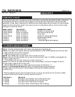
FCC ID NOTICE
This device complies with Part 15 of the FCC rules. Operation is subject to the following conditions:
1. This device may not cause harmful interference, and
2.This device must accept any interference received, including interference that may cause undesired operation.
CAUTION: Changes or modifications not expressly approved by the part responsible for compliance void the user’s authority to operate
this devise.
REV.2011.7.22
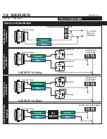
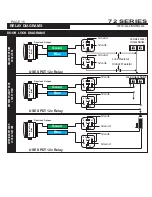
72 SERIES
Advanced Remote Starters & Vehicle Security Systems
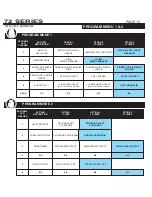
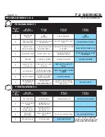
THIS MANUAL COVERS THE OPERATIONS OF
THE 1172 AND 1272 SERIES REMOTE VEHICLE
STARTERS
WARNING: NEVER USE AN AUTOMATIC TRANSMISSION
STARTER IN A MANUAL TRANSMISSION VEHICLE
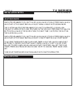
INSTALLATION MANUAL


